PYI NRG MARINE SONIHULL MONO User manual

WWW.PYIINC.COM

INstallINg a sONIhull sYsteM
Congratulations on your purchase of the Sonihull ultrasonic antifouling system. This manual
will help you go through the simple steps of installing either the Sonihull Mono or Sonihull
Duo systems, or multiples thereof depending on the size of your yacht.
The Sonihull is suitable for berglass, aluminum, steel and cement hulls, where the
transducer can be bonded to the inside of the outer skin of the hull. If your yacht is a sandwich
construction we strongly recommend using the services of a professional marine engineer,
as the outer skin will involve cutting through the inner skin and removing some of the inner
core lling to expose the inside surface of the hull.
Please note that the Sonihull system is not suitable for wooden boats due to the poor
transmission of the high frequencies through wood.
For concrete hulls to achieve the best result it is recommended that you double the number of
transducers required compared to the illustrations in this manual to achieve the best results.
IMPORTANT SAFETY CONSIDERATIONS
It is highly recommended that the electrical installation of this system is installed only by a
competent marine electrician.
When mounting the control box please nd a suitable dry position above the water line.
Connect all AC connections in accordance with IEC wiring regulations, ensuring the correct
plug and socket are used, or directly to a 5 amp breaker.
Color codes for main cable provided Brown = positive Blue = negative. If connected to DC
supply please ensure that an inline 5 amp fuse is used.
IF IN DOUBT CONTACT A PROFESSIONAL

COMPONeNts INCluDeD
SONIHULL DUO
• Sonihull control unit
• 2 ultrasonic transducers with 18
feet of cable
• Mains cable with 3 pin UK standard
fused plug
SONIHULL MONO
• Sonihull control unit
• 1 ultrasonic transducer with 18 feet of
cable
• Mains cable with 3 pin UK standard
fused plug
Items required but not supplied with the Sonihull Kit:
• 4 screws for mounting control box (some people prefer to use strong Velcro
to secure)
• Marine grade epoxy glue (Araldite or equivalent)
• Medium grade sand paper

ChOOse sONIhull MONO OR DuO POsItIONINg
aCCORDINg tO WhICh tYPe OF YaCht YOu haVe
SONIHULL MONO POSITIONING SONIHULL DUO POSITIONING
SONIHULL DUO POSITIONING TWO SONIHULL DUO SYSTEMS
USE ONE FOR EACH HULL
Positions shown are for illustration and
guidance only. Actual mounting is on the
inside of the boat hull.
For vessels in excess of the sizes
shown please contact PYI Inc for
recommendations.
NOTE: Twin hull vessels will require the
recommendations on the image to the
left to be doubled.
≤ 32 FEET = MONO
32 FEET - 55 FEET = DUO
49 FEET - 65 FEET = MONO +DUO
59 FEET - 72 FEET = DUO +DUO

lOCatION OF tRaNsDuCeRs &
INstallatION OF the sONIhull CONtROl uNIt
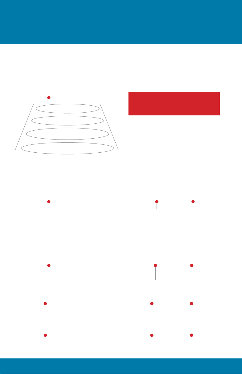
LOCATION OF TRANSDUCERS
The following is a guide line for the best
location to install on your yacht. The pictures
are for illustration only as the transducers
will be mounted on the inside of the hull.
The aft transducer should be mounted
close to the center line of the hull in the
rear 1/3 of the boat in close proximity to the
propeller shafts, steering gear and trim tabs
to provide the best possible protection.
For the Duo, the front transducer should
be mounted approximately 2/3 of the way
along the boat, again close to the center
line of the hull.
For yachts over 60 feet please consult with
PYI Inc for advise on the best location for
the transducers.
For twin engine yachts we recommend
that a Duo system be installed, with one
transducer installed above close to each
propulsion unit, thus providing protection to
the stern drive itself as well as the hull.
INSTALLATION OF THE SONIHULL
CONTROL UNIT
Once the Sonihull system is installed you
will nd that there is little maintenance
required due to the systems sophisticated
technology. Therefore your Sonihull Control
Panel can be installed out of sight, in a
cupboard or even in the engine room itself.
As with any electrical appliance it is wise to
check the system periodically to ensure that
the system is powered and working.
Find a suitable dry location above the water
line, with suitable access to either mains or
DC power. Please also consider that the
location should be suitable for access to the
transducers.
MAINS AC supply only. 100-240 VAC 50/60
Hz. Replace lid and plug into suitable AC
socket. If socket is not available please
consult a competent marine electrician to
carry out any electrical installation.
DC only supply. 12-24 V DC
SAFETY - ensure that the cables are
supplied via 5 amp fuse.

eNsuRe that the suPPlY Is IsOlateD
BeFORe staRtINg the DC CaBle INstallatION
Mains cable can be totally removed or simply coiled for potential future use.
Connect to DC through a 5 amp inline fuse.
Please ensure correct polarity.
TRANSDUCERS ARE TO BE MOUNTED DIRECTLY TO THE INNER SKIN OF
THE HULL. IF THE HULL IS A SANDWICH CONSTRUCTION PLEASE CONSULT
A MARINE SPECIALIST.
1. Once you have located a suitable location for the mounting the transducer, close to the
center line of the hull, paying special attention to be sure that there is enough head room
to replace the oor / deck plate, and that there is suitable access for running the cables
back to the Sonihull controller.
2. Prepare the hull by sanding down the area to ensure a smooth at surface, (it is
important that both the hull and the transducer surfaces are flat to ensure the best
possible surface to surface transmission of the transducer pulse).
3. Clean the hull and transducer faces to ensure there is no dust or grease.

MOUNTING RING
1. Apply a thin layer of petroleum jelly
to the thread of the mounting ring.
Ensuring to keep the outer face of the
ring free from any grease. (This is to
stop any epoxy from accidently getting
stuck in the threads).
2. Prepare the marine epoxy as per the
manufacturers instructions. You will
note on the mounting ring that a gutter
has been provided to try and capture
any stray epoxy before it gets to the
thread. Apply the epoxy to the face of
the mounting ring, on the outside of
the gutter and attach to the hull. It is
important to epoxy the full “circle” of
the transducer to make a complete
seal with the hull once set.
3. Allow the epoxy to fully set prior to
attaching the transducer.
ATTACHING THE TRANSDUCER
1. Prior to screwing in the transducer to
the mounting ring cover, a thin layer
(1mm) layer of petroleum jelly should
cover the face of the transducer. This
will enable better contact between the
surface of the transducer and the hull.
2. Screw in the transducer fully into the
mounting ring, ensuring a rm contact
has been made with the hull. Do not
over tighten as this could cause the
epoxy to break.
3. Run cables to the Sonihull controller
and then connect.
4. If you have already run the transducer
cables please wind the transducer
back (counter clockwise) about 8
rotations so not to leave the cable
twisted once you have screwed the
transducer to the mounting ring.
INstallINg a tRaNsDuCeR
TECHNICAL SPECIFICATIONS
Power Supply Approvals: UL and CE
Voltage: 100 - 240 vAC 50/60 Hz
12-24v DC
Power: Sonihull Mono: 3.6 Watts
Sonihull Duo: 7.2 Watts
Ultrasonic Generator
Pulse Frequency: 17 kHz - 59 kHz
Control Box Rating: IP65
Transducer Rating: IP68
Transducer Cable Length: 18 feet
Weight: 6.6 lbs
Dimensions (inches): 6.8 x 5 x 3
Warranty: 1 year

PYI Inc.
12532 Beverly Park Road
Lynnwood, WA 98087
Tel: 425-355-3669
800-523-7558
Fax: 425-355-3661
Email: [email protected]
Website: www.pyiinc.com
1-82113
This manual suits for next models
1
Table of contents
Other PYI Marine Equipment manuals
Popular Marine Equipment manuals by other brands

Seagull
Seagull EXELOR Assembly instruction

Raymarine
Raymarine H6 System installation manual

KVH Industries
KVH Industries TracVision R6 DX Replacement instructions

Facnor
Facnor R 80 installation manual

FLIR
FLIR Raymarine HD DIGITAL RADOME installation instructions

Kongsberg
Kongsberg HOS 152 - DATASHEET REV A datasheet