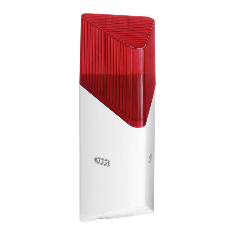
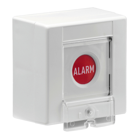
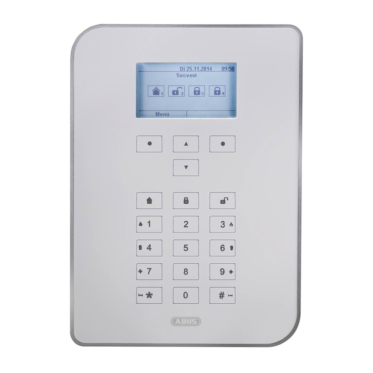
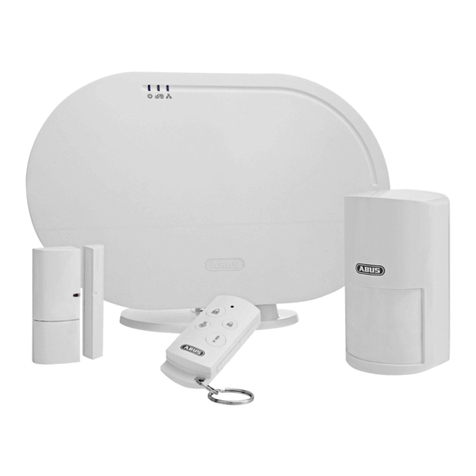
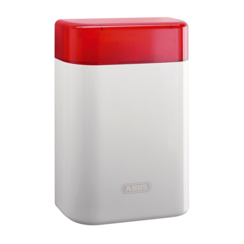
Abus Secves FU8007 User manual
Other Abus Security System manuals
Abus
Abus Security-Center EcoLine TV7000 User manual
Abus
Abus FG300A User manual
Abus
Abus FUAA35010A User manual
Abus
Abus PPIC90010 User manual
Abus
Abus Terxon MX User manual
Abus
Abus FUEM30000 User manual

Abus
Abus TVAC71000 User manual

Abus
Abus Terxon MX User manual
Abus
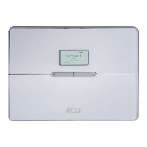
Abus WIRELESS ALARM SYSTEM User manual
Abus
Abus Secvest 2WAY User manual
Popular Security System manuals by other brands

Inner Range
Inner Range Concept 2000 user manual

Climax
Climax Mobile Lite R32 Installer's guide

FBII
FBII XL-31 Series installation instructions

Johnson Controls
Johnson Controls PENN Connected PC10 Install and Commissioning Guide

Aeotec
Aeotec Siren Gen5 quick start guide

IDEAL
IDEAL Accenta Engineering information

Swann
Swann SW-P-MC2 Specifications

Ecolink
Ecolink Siren+Chime user manual

Digital Monitoring Products
Digital Monitoring Products XR150 user guide

EDM
EDM Solution 6+6 Wireless-AE installation manual

Siren
Siren LED GSM operating manual

Detection Systems
Detection Systems 7090i Installation and programming manual
