Molift QUICK RAISER User manual

- a patient lifter from

Page 2 of 20 E Rev. G/ 09/2006
IMPORTANT!
The patient lifter is only meant to be used by
qualied personnel.
The manual shall not be handed over, or made
available to, any unauthorised third party, wit-
hout a prior written consent from Molift AS.
Exciting laws, conventions and agreements
protects all documents. No extract of this do-
cumentation can be reproduced, used or trans-
ferred without prior written consent from Molift
AS. Violation of these regulations may lead to
judicial repercussions and economic responsi-
bility. Industrial rights are reserved.
Molift AS
Ole Deviksvei 44
0668 OSLO, Norway
Teleph:(+47) 40001004 www.molift.com
Contents
General advice.................................................. 3
Explanation of symbols ............................... 3
Before using the patient lifter ...................... 3
Responsibility .............................................. 3
Safety precautions .......................................... 4
General ....................................................... 4
Use under moist or wet conditions .............. 4
If defects or faults occur .............................. 4
Lift and transfer ........................................... 4
About the product............................................ 5
Main components........................................ 5
Safety devices............................................. 5
Technical data QR1 ......................................... 6
Technical data QR2 ......................................... 7
Technical data QR2+ ....................................... 8
Assembly /disassembly ................................. 9
Assembly and use of charger...................... 9
Unpacking ................................................... 9
Assembly of lifter......................................... 9
Checklist before use ................................ 10
Disassembly.............................................. 10
Operation..........................................................11
Battery care................................................11
Battery capacity..........................................11
Battery types and chargers ........................11
Operation of hand control.......................... 12
QR......................................................... 12
QR2 and QR2+ ....................................... 12
Emergency stop and lowering................... 12
Using lifting slings ..................................... 12
Use of spreadable legs (QR2 and QR2+) . 12
Lift and movement..................................... 12
Lifting..................................................... 12
Movement .............................................. 14
Lowering ................................................ 14
Accessories .................................................... 15
Molift Easy Raiser lifting strap................... 15
Molift Easy Raiser lifting strap with support 15
Lifting strap size guide ............................ 15
Maintenance.................................................... 16
Daily maintenance..................................... 16
Monthly maintenance ................................ 16
Fault nding............................................... 16
Service / yearly maintenance ................... 17
Notes:........................................................ 17

Page 3 of 20
General advice
This user manual contains important safety instruc-
tions and information regarding the use of the lifter.
Carefully read the manual before using the lifter in
order to be familiar in the function and use of the
lifter.
Explanation of symbols
This symbol is used to point out instructions
and information related to work place safety
where injury may occur if the information is
disregarded or ignored. Follow these instruc-
tions, be careful and attentive at all times.
This symbol indicates important information
regarding the use of the equipment. If not
taken into consideration, it may lead to dam-
age or functional defects to the lifter or other
equipment.
This symbol indicates important and useful
information. If taken into consideration, it
will help the operator of the lifter to work ef-
ficiently. It may help simplify routines and to
explain complicated facts.
Before using the patient lifter
Before using a patient lifter, the operator must be
trained accordingly. Practice lifting a colleague, and
be lifted by others. It is important not only to know
how to move another person using the lifter, but also
how it is to be lifted. Try out and practice using all
the relevant slings for the different types of lifter and
movement you may encounter. Before lifting a per-
son, you should explain the procedure.
When using the lifter, it’s also important to use the
correct sling and accessories according to:
• type of disability
• size
• weight
• type of movement
Responsibility
Please read these operating instructions carefully
before putting the product into operation. We as-
sume no liability for damage or malfunctions re-
sulting from failure to comply with the instruc-
tions. Warranty claims must be made immediately
on detecting the defect. Remember to quote the se-
rial number. Consumable parts are not subject to the
warranty.
All technical information, data and instructions for
operation contained in these operating instructions
were up-to-date at time of print and are compiled
on the basis of our experience and to the best of our
knowledge. We reserve the right to incorporate tech-
nical modications within the scope of further de-
velopment of the product described in this manual.
No claims can be derived from the information, il-
lustrations or descriptions contained in these in-
structions. We assume no liability for any damage or
malfunction caused by operating errors, non-com-
pliance with these operating instructions or inappro-
priate maintenance. We expressly point out that only
genuine Molift AS spare parts and accessories ap-
proved by us may be used. For safety reasons, the
tting and use of spare parts or accessories, which
have not been approved, and unauthorised modi-
cation or conversion of the product, are not permit-
ted. Molift AS will accept no liability for damages
resulting from such acts.
With the exclusion of product liability, Molift AS
is liable for faults or omissions on its part within
the scope of the warranty obligations stated in the
purchase contract. Claims for damages are exclud-
ed, irrespective of the legal reason from which such
claims are derived. Only documentation belonging
to the actual equipment is valid.
Any failure to comply with the safety regulations
and precautionary measures stated in these operat-
ing instructions renders the declaration of conform-
ity supplied with the system in accordance with
Council Directive (93/42/EEC) concerning medical
devices invalid.

Page 4 of 20 E Rev. G/ 09/2006
If defects or faults occur
The lifter must be switched off immediately if one
of the following conditions occur;
• damage to electrical devices or cables, or damage
to parts of electrical insulation
• damage or failure on safety devices
If the expected movement does not start when
the corresponding button is pressed, please
consult the fault finding table in the mainte-
nance chapter to locate the fault.
Injury to personnel or equipment may occur if
Molift QUICK RAISER is used in an incorrect man-
ner and if:
• covers are removed by unauthorised personnel
• used incorrectly
• insufcient maintenance
• load exceeds maximum limit. The maximum
load stated in this manual and on the lifter is the
maximum load
• unauthorised repair of electrical devices or cables
Lift and transfer
The patient lifter may tip over if used incor-
rectly! Ignorance of warnings and instruc-
tions may lead to personnel injury. Read in-
structions carefully before attempting to lift
anyone.
Stand to the side of the user when lifting. Ensure that
arms and legs are clear of the lift, chair, bed etc. Try
to maintain eye contact with the user - this will help
the user feel safe and comfortable.
Pay close attention to your actions. Ensure
that both ropes of the sling are securely fas-
tened to avoid the user slipping or falling.
Keep fingers, arms or similar away from trol-
ley during use! Danger of clamping between
knee support and trolley.
Molift slings shall ONLY be used to lift per-
sons. NEVER use the sling to lift and/or move
objects of any kind.
Safety precautions
General
This operator manual is valid for all types of QUICK
RAISER. Use and operation of the variants are ba-
sically similar and any major difference is clearly
noted in the text.
Before putting a Molift QUICK RAISER into oper-
ation, the operator must ensure that the lifter and ac-
cessories are in good working order, especially with
regards to safety.
All instruction and information in this manual re-
garding safety and general precautions must be read,
understood and followed carefully. Any disregard to
these precautions may result in personnel injury or
damage to the equipment. The lifter must be taken
out of service immediately, or not returned to serv-
ice, if faults and/or irregularities that may have in-
uence on the safety are discovered.
Safety devices and -equipment must not be re-
moved, disabled or in any other way altered. A
Molift QUICK RAISER shall only be used when all
safety devices and equipment is in place and fully
operational.
The lifter is designed for use in room tem-
perature, +10 to +40 °C. This should be
taken into consideration when transporting
the lifter, and therefore keeping it in a tem-
perate part of the vehicle. Alternatively, the
lifter must rest in a temperate room until the
equipment has achieved proper working tem-
perature.
Use under moist or wet conditions
The lifter is splash proof. If used in conjunction with
shower equipment, a protective plastic bag must be
used to cover the operator panel. Avoid direct show-
ering of the lifter. Permanent use in shower rooms is
not recommended and can - over time - lead to corro-
sion of details on the lifter. If used in shower rooms,
it is mandatory to prevent excessive use of water as
well as increasing service and maintenance.

Page 5 of 20
About the product
Molift QUICK RAISER is designed to cover the
need for lift and transfer of patients who are to some
extent capable to actively participate in the process.
The lifter has an exceptional design and the shape of
the lifter and geometry of the lifting movement im-
itates the natural pattern of movement of a person.
The lifter is only intended for lift and transfer to and
from a sitting position.
The lifter is delivered in three variants; QUICK
RAISER (QR) with xed legs and QUICK RAIS-
ER 2 (QR2) and QUICK RAISER 2+ (QR2+) with
spreadable legs, making the lifter more exible
when used around different chairs, toilets etc. In ad-
dition QR2+ has lifting capacity of 200 kg. QR and
QR2 have lifting capacaties of 160 kg.
The kneepads are adjustable giving comfortable
support for the knees. A strap is placed around the
legs, xing the knees gently to the pads to ensure
stability and comfort. The pads are self adjusting
and can be removed for maintenance.
The lifting arm has handles with rope locks. The lift-
ing arm can be folded towards the column when pre-
paring a lift, - this makes the lifter less intimidating
and prevents collisions between the lifting arm and
patient.
Main components
The chassis is the main part of the QUICK RAISER
consisting of a steel frame, casters, footplates and
emergency stop. The front legs are xed on QR and
spreadable on QR2 and QR2+.
The lifting column is xed at the centre of the chas-
sis. The column is made of an aluminium prole
with a trolley. The trolley runs along a worm screw
powered by an electric motor inside the chassis. A
driving handle is placed near the top of the column,
and the battery/-holder is situated below. The knee
pad bracket is also fastened to the column, and is ad-
justable.
The lifting arm is connected to the trolley, and has
two rope locks to fasten the sling ropes.
Safety devices
The lifter has an overload sensor preventing the lifter
to be operated with more the maximum load. If the
load exceeds the maximum limit, the lifter will stop
the movement.
Lifting arm
Drive handle
Battery/-holder
Emergency stop
Chassis
Trolley
Lifting column
Knee support w/
pads
Footplate

Page 6 of 20 E Rev. G/ 09/2006
Lifting capacity (max):
160 kg
Lifting height (along column):
850 mm
Height legs:
Max 100 mm
Measurements:
1070 x 610 x 1280 mm (LxWxH)
Measurements in illustrations below are in millime-
tres.
Technical data QR1
Material:
Aluminium lifting column
Steel chassis and suspension
Lifting motor:
12 V DC w/worm gear
Linear worm screw with trolley
Weight, total:
Incl. battery: 30 kg
Battery:
14,4 V NiCd 1,9 Ah or 14,4 V NiMH 2,2
Ah, Molift PowerPac
Number of lifts (75 kg, 500 mm up/down):
Ca. 40

Page 7 of 20
Technical data QR2
Material:
Aluminium lifting column and spreadable
legs
Steel chassis and suspension
Lifting motor:
12 V DC w/worm gear
Linear worm screw with trolley
Leg motor:
12 V DC linear actuator
Weight, total:
Incl. battery: approx.. 37 kg
Battery:
14,4 V NiCd 1,9 Ah or 14,4 V NiMH 2,2
Ah, Molift PowerPac
Number of lifts (75 kg, 500 mm up/down):
Ca. 40
Lifting capacity (max):
160 kg
Lifting height:
850 mm
Height legs:
Max 100 mm
Measurements:
1350 x 610 x 1250 mm (LxWxH)
Measurements in illustrations below are in millime-
tres.

Page 8 of 20 E Rev. G/ 09/2006
Technical data QR2+
Material:
Aluminium lifting column and spreadable
legs
Steel chassis and suspension
Lifting motor:
12 V DC w/worm gear
Linear worm screw with trolley
Leg motor:
12 V DC linear actuator
Weight, total:
Incl. battery: approx. 38 kg
Battery:
14,4 V NiCd 1,9 Ah or 14,4 V NiMH 2,2
Ah, Molift PowerPac
Number of lifts (75 kg, 500 mm up/down):
Ca. 40
Lifting capacity (max):
200 kg
Lifting height:
820 mm
Height legs:
Max 100 mm
Measurements:
1350 x 610 x 1250 mm (LxWxH)
Measurements in illustrations below are in millime-
tres.

Page 9 of 20
Assembly /disassembly
To be able to operate the lift, the operator must have
good knowledge of the lift, including assembly, dis-
assembly and preparation before use.
Assembly and use of charger
The battery charger shall be mounted on a vertical
wall surface close to a power outlet. The charger
shall be connected to the power outlet at all times.
Molift AS tests and charges all batteries be-
fore packing and shipment. However, all bat-
teries must be charged before use.
Unpacking
• The lifter comes in a cardboard box. Verify that
the box has no apparent damage. If damaged, -
check the contents and contact your dealer for as-
sistance if components are damaged.
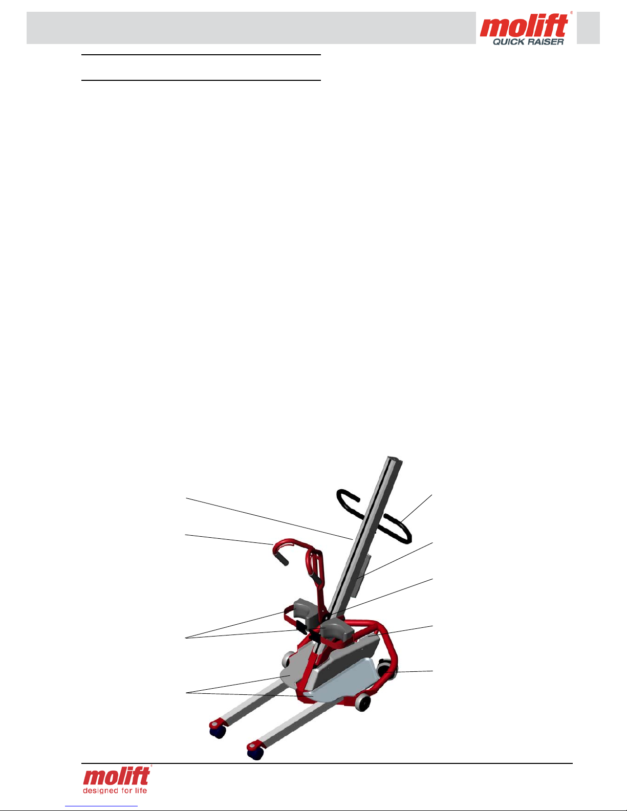
• The box contains chassis, lifting column, knee
support, lifting arm, drive handle, hand control,
battery, battery charger and documentation.
Make sure that the different parts have the
same lifting capacity. If in doubt, the part
with the lowest capacity is the ruling .
Assembly of lifter
The battery must not be in the battery holder
on the column during assembly!
• Assemble the kneepad bracket rst by sliding it
onto the lifting column. In order to do that, you
must rst remove the column xing bolts and -
plate. Guide the knee support bracket onto the
column with the head of the xing knob into the
T-groove on the column. Slide the bracket up the
column to the desired position and tighten the
knob.
• Retrieve the column xing bolts and -plate and
slide it into the T-groove at the base of the col-
umn and approx. 25mm up. Tighten one of the
screws slightly to x the plate. Insert the col-
umn into the chassis - the arrow on the column
side shall be exactly aligned with the edge of
the chassis. If the column stops before the arrow
has reached the edge, you will have to retract the
column and try turning the motor spline head to
align it with the connector at the base of the col-
umn. Do not use force to press the column down.
When the column is in place, release the column
xing bolt and let the plate with bolts slide into
the corresponding groove on the chassis. Tighten
the bolts rmly using the tool found at the top of
the column.
The QR2+ column has a pin in the bottom to
be fitted in the chassis.
• Slide the driving handle onto the top of the col-
umn by guiding the head of the xing knob into
the T-groove of the column. The handle shall be
pointing upwards. Tighten the knob rmly when
the handle is in the desired position.
• Guide the wire of the hand control through the
ring at the base of the drive handle and insert the
contact into the chassis connector. The hand con-
trol has a hook enabling it to hang on the handle.
• Attach the lifting arm.
QR2: Remove the security ring from the lifting
arm. Assemble the lifting arm by holding it ap-
prox. parallel to the column and guide the hook
of the arm onto the two bolts of the trolley. The
arm is now attached to the trolley. Mount the se-
curity ring.
QR2+: Place the lifting arm, install the bolt and at-
tach with the screws. Torque 28 Nm.
If the lifting arm appears wobbly in the trolley,
try tightening the bolts on each side of the trolley
to reduce the gap.
Be careful not to put fingers or similar under
the lifting arm between arm and trolley. Dan-
ger of personnel injury.
• Place the battery in the battery holder with the
connectors facing down. Run each function of
the lifter a couple of times without load to verify
proper function.
Molift AS tests all lifters with and without
load before shipment. The control is an extra
precaution to uncover any shipment damage
and/or incorrect assembly.

Page 10 of 20 E Rev. G/ 09/2006
Checklist before use
• Verify that the lifting arm is properly fastened to
the trolley
• Verify that the lifting column is properly placed
into the chassis - arrow shall be exactly aligned
with the edge of the chassis
• Verify that the column is properly fastened with
bolts tightened
Disassembly
• Remove the lifting arm
• Remove the knee support
• Loosen the column xing bolts and lift out the
column
• Alternatively remove the drive handle and knee
support bracket

Page 11 of 20
Operation
Battery care
Molift PowerPac system is a battery with a 14,4 V
cell unit that is placed in the battery holder on the
lift. A charger is also supplied to charge the battery
whenever needed.
This battery system is the same on all of Molift’s
mobile lifts.
The power cable of the charger should be connected
to the power outlet at all times (verify that the charg-
er is suitable for the local power system voltage).
Place the battery in the holder according to the ar-
row markings. Press the battery gently down to en-
sure good contact between battery and charger.
Battery capacity
A LED (Light Emitting Diode) is situated on the bat-
tery holder. If the voltage of the battery falls below
a certain level, the diode will change to orange, in-
dicating the need for charging. There is still enough
capacity to perform 3-5 lift cycles (75 kg) at this
point.
If the battery is discharged during a working ses-
sion, it’s recommended to have two batteries, so a
second charged battery is available when needed.
If the battery is discharged during a lift, it is
always enough power to lower the user down
again.
Battery types and chargers
Molift PowerPac can be used with two kinds of bat-
teries; NiCd and NiMH.
The battery and charger types must not be
mixed. Use of wrong charger to battery type
may cause overheating and damage to the
powerpac
Be aware that these two batteries have differ-
ent chargers. Follow the instructions printed
on the battery.
It’s not possible to overcharge the batteries,
but to ensure optimal performance through-
out the lifetime of the battery, we recommend
that the battery is allowed to rest for a cou-
ple of minutes after charging to cool down
before use. It is also important that fully
charged batteries are not charged without
being used.
The chargers have different ways of showing the
status of the charging process.
• NiCd-charger
The charger has a LED indicating the status of
the battery as described below:
LED Mode Output
Yellow No battery 25 V
Yellow Initalization (10 sec) 100 mA
Orange Fast charge 1,8 A
Green/yellow Top-off charge 270 mA
Green Trickle charge 100 mA
Orange/green Error 100 mA
It is recommended that NiCd batteries are
placed in the charger when not in use. Reg-
ularly (each 10 times) the battery should be
used until the charging indicator on the lifter
glows, before charging the battery.
• NiMH-charger
The charger has two diodes - a green and a red.
The red diode will glow as soon as the battery is
placed in the charging unit and maximum charg-
ing current is applied. The green diode will start
to glow when the battery is fully charged and
the charger switches to maintenance charging.
If the charger can’t detect fully charged battery
after about 8 hours, a built in timer will force
the charger to maintenance mode to avoid over-
charging.

Page 12 of 20 E Rev. G/ 09/2006
Operation of hand control
QR
The hand control has two buttons; up and down
QR2 and QR2+
The hand control has four buttons; two buttons for
movement up and down, and two buttons for move-
ment of the legs in and out.
Emergency stop and lowering
All of the Molift patient lifts are equipped with
emergency stop and lowering. The emergency stop
will cut the power to the actuator, and is situated on
the chassis. Turning it clockwise until it pops out
will reset the emergency button.
It is possible to perform a emergency lowering if the
lifter should malfunction. This is done manually by
turning the worm screw using a Umbraco tool.
Move the lifter to a suitable place to lower the per-
son. Break the yellow seal on the top of the column
and insert the tool. Turn counter clockwise to lower
- the trolley will move slowly down.
Contact a service partner if the cause of the
stop or malfunction is unknown or if a fault is
discovered.
Using lifting slings
The Easy lifting slings are, as the name indicates,
easy to use. They are washable at 80º C and auto-
clave at 85 ºC for 30 minutes.
It is recommended to use Molift Easy slings.
Slings from other manufacturers may have
other specifications leading to unexpected
instability and possible injury to personnel.
Torn, cut, frayed or broken slings can fail,
resulting in serious injury to the user. Use
slings in good condition only. Destroy and
discard old, unusable slings.
Use of spreadable legs (QR2 and QR2+)
It is possible to adjust the width of the legs at the
front of the QR2 and QR2+ - this makes it easier
to access lifting situations around chairs, toilets etc.
The adjustment of the legs are done with the hand
control and does not affect the stability of the lifter.
Lift and movement
Lifting
• Lower the lifting arm to the lowest position
• Alternatively adjust the legs of the QR2 to adapt
to the lifting situation
To perform a comfortable lift for the patient,
it is recommended that the patient is sitting
in a normal upright position with near 90° in
ankles, knees and hips/torso. It is also recom-
mended that the patient is wearing suitable
shoes or socks with good friction towards the
floor.
If the patient is sitting in a wheelchair, it is
necessary to put on the wheel chair brakes.
It’s also recommended to lock the wheels of
the QR when performing the lift.
Patients with an extremely high or displaced
centre of gravity (i.e. lameness on one side of
the body or high wieght on the upper body)
may cause the lifter to tip over. Such patients
should be lifted in a passive lifter, i.e. Molift
Partner or Molift Smart, and not with a semi-
active lifter as Quick Raiser.

Page 13 of 20
• Move the QR in front of the patient and place it
in such a way that the patient can place the feet
on the footplate on the chassis. If necessary -
help the patient placing the feet correctly.
The distance from the front edge of the lit-
er to the kneepads increases when they are
moved upwards. The distance X is minimum
15 cm og maximum 29 cm on QR. QR2 and
QR2+ has a minimum distance on 14 cm og
maximum distance on 28 cm.
• Adjust the height of the kneepads so that the top
of the pads are approx. two ngerwidhts under
the kneecap.
If it proves to be impossible to place the leg
perpendicular to the footplate, you should
pay extra attention when lifting to avoid
overstretching the knee joint.
• Place the Molift Easy Raiser sling under the arms
and around the back of the patient as far down as
possible. Connect the belt and tighten rmly.
• Fasten the sling to the lifting arm by pulling the
ropes rmly into the rope locks from the inside
and out as shown in the illustration. When lifting
the patient, the ropes will lock even tighter due to
the weight of the patient. The patient should grab
and hold the handlebars of the lifting arm if pos-
sible.
If the patient is large and heavy, it is recom-
mended to lock the rope from the outside and
in to increase the width of the ropes. This will
reduce any pinching effect to the patients
chest.

Page 14 of 20 E Rev. G/ 09/2006
• On QR2+ the ropes is attached to the lifting arm
bt pulling them rmly from above into the rope
locks as shown on the illustration.
The ropes must be tightened firmly to avoid
them sling to much when lifting the patient.
The rope will lock itself due to the weight of
the patient, but if sliding too much before
locking, it may cause an uneven lift and dis-
comfort for the patient.
• Raise the patient carefully until the buttocks are
clear from the seating. Unlock the wheels on the
lifter and move the patient to the next location.
Movement
The patient should not be standing straight
up during movement - this can be experi-
enced as uncomfortable.
Be careful during movement not to run into furni-
ture, walls, doors etc.
The lifter shall not be used to lift or move us-
ers on sloping surfaces.
Avoid deep pile carpets, high thresholds, uneven
surfaces or other obstacles that may block the cas-
tors. The lifter may become unstable if forced over
such obstacles increasing the risk of tipping over.
The lifter shall only be used for movement
over short distances. It is not a replacement
for wheelchair or similar.
Lowering
• Lower the patient into sitting position at the de-
sired place
If the patient is to be seated into a wheelchair,
please observe that the wheel brakes must be
locked on the wheelchair when lowering, but
NOT on the lifter.
• Release ropes from locks and remove the sling

Page 15 of 20
Accessories
Molift Easy Raiser lifting strap
Size Molift Easy Raiser
XS Art. no 3020003
S Art. no 3020000
M Art. no 3020001
L Art. no 3020002
XL Art. no 3020004
Molift Easy Raiser lifting strap with support
Size Molift Easy Raiser with
support
XS Art. no 3019003
S Art. no 3019000
M Art. no 3019001
L Art. no 3019002
XL Art. no 3019004
Separate support strap
XS/S/M Art. no 3019011
L/XL Art. no 3019012
Lifting strap size guide
The strap is adjustable
Size Colour
code
Recom-
mended
weight
Waist meas-
urement
min max
(cm) (cm)
XS Light
blue
20-30 kg 50 65
SRed 30-50 kg 60 90
MYellow 50-90 kg 75 110
LGreen 90-160 kg 100 150
XL Blue 160-200 kg 120 180
All lifting straps are approved for 200 kg,
Recommended weight is only mentioned as a
guide to choose the correct size.

Page 16 of 20 E Rev. G/ 09/2006
Maintenance
Daily maintenance
Detergents must be pH-neutral. Do not use
solvents or strong liquids - this may damage
surfaces on the lifter. For disinfection when
needed; use isopropyl alcohol. Avoid abra-
sive cleaning products.
Clean surfaces with a damp cloth using an appropri-
ate detergent.
Monthly maintenance
• Remove hair and pile from the castors and verify
that the castors rotates without abnormal friction
• Verify that the contacts of the hand control and
charger is rmly in place
• Clean contact and hand control with spirit or
similar to remove grease and dirt
• Verify that the cables for the hand control, actua-
tor and charger are intact
• Run the lifter up and down to verify that it runs
normally and without any abnormal noise
Fault nding
If you have access to more than one lifter, it may be
helpful to change parts across lifters to help identify
any faults. For instance, if you suspect the fault to
be inside the column, exchange the column with at
functional one from the other lifter to see if the prob-
lem is xed.
Across you will nd a table with fault nding proce-
dures to identify and correct faults on the lifter:
Symptom Possible cause/action
Lifting column is
wobbly
Locking bolts are not prop-
erly secured or lifting column
is not properly in place in the
chassis / check if the col-
umn is correctly placed in the
chassis and/or tighten bolts
Lifter only moves
one way (up or
down) / legs only
moves one way
(in or out)
Fault on hand control / ex-
change with alterative control
from other lifter and/or new
hand control
One of the relays / electronics
has failed/ exchange the con-
trol unit/relays / contact your
local service representative
The lifter moves
up and/or down
by itself / legs
move by them-
selves
Short circuit between the
hand control and lifter / clean
the connectors of the hand
control and chassis with spir-
its to remove grease and dirt
The hand control has failed/
exchange hand control / con-
tact your local service repre-
sentative
Relays/electronics malfunc-
tions / exchange electron-
ics/relays / contact your local
service representative
The lifting arm
does not move
/ legs does not
move
Discharged battery / ex-
change battery with another
or charge battery
Bad or wobbly connection
from lifting column to chas-
sis / clean contacts in column
base and inside chassis - ad-
just and tighten column bolts
Emergency stop activated /
turn clock wise to reset
Hand control disconnected /
reconnect hand control
The hand control has failed/
exchange hand control / con-
tact your local service repre-
sentative
Relays/electronics malfunc-
tions / exchange electron-
ics/relays / contact your local
service representative
Motor has failed / exchange
motor / contact your local
service representative

Page 17 of 20
Service / yearly maintenance
If you are not able to solve the fault or problems by
yourself using this manual, please contact local au-
thorised service representative. If you do not know
whom to contact locally, please contact your dealer
or Molift AS to get help.
Yearly service is done according to procedures in
the service manual included with the lifter.
The owner is responsible to ensure proper logging
and written verication performed by authorised
service partner. The service manual has dedicated
pages for logging and signature.
Notes:

Page 18 of 20 E Rev. G/ 09/2006
WARRANTY
Molift AS hereby declares that this product is awarded up to 5 - ve - year extended manufacturer’s
warranty.
It is very important to our customers and to Molift AS that our products meet all relevant quality and sa-
fety requirements according to both customer and authority demands. Molift AS develops and manufac-
tures products with high standards of safety, quality and design, and we are continuously in a process of
keeping our products in position among the market leaders.
To make our products quality level more explicit Molift AS have introduced extended warranty time on
all of our patient lifters. A 5 - ve - year* warranty against defects which might be traced back to ma-
nufacturing is offered. The extended warranty period is offered under the condition that the regulations
described here are completely fullled and that the product has been used according to its intentions.
The extended warranty is valid for a period of 5 - ve - years starting at the date of purchase limited to
3 months after the production year/week. The extended warranty is offered in addition to the local sale
of goods act. It is mandatory that the product undergoes safety control and maintenance performed by
an authorised service partner at least every 12 months according to this service manual made by Molift
AS.
• Yearly maintenance and safety control must be performed within a maximum interval of 12 months
and for the rst time maximum 12 months after date of purchase or maximum 15 months after year/
week of production.
• Molift AS will cover the cost of spare parts and labour in the warranty period for all necessary re-
pairs caused by product defects that can be traced back to manufacturing. The repair must be perfor-
med by an authorised service partner or at Molift AS’ own workshop during the warranty period.
• All warranty repairs must be approved by your Molift supplier or by Molift AS prior to the repair.
• The owner of the product is responsible for establishing the service agreement, and the cost for the
annual safety control and maintenance.
• The service manual has one page for every 12 months containing checkpoints for maintenance and
safety control. The extended warranty is valid only with signature and/or stamp by authorised service
partner including service partner’s signed label with authorisation no. on product.
*Normal warranty is 12 months. This still applies for slings, hand control, batteries and paint.
Gjøvik 28.08.2006
Molift AS
__________________
Geir Olav Farstad
Managing Director

Page 19 of 20
DECLARATION OF CONFORMITY
Molift AS
Ole Deviksvei 44
0668 OSLO
NORWAY
Telephone: + 47 40 00 10 04
hereby declare that:
Molift QUICK RAISER patient lifter
and that the accessoires used only together with this product
Year: 2006
are in conformity with:
• The Council Directive concerning medical devices (93/42/EØF)
and according to this classied as medical equipment class 1
Molift QUICK RAISER is manufactured in conformity with the following national or
international standards that also might implement a harmonised standard:
• ISO10535 Hoists for the transfer of disabled persons - Requirements and test methods
• ISO 14971 Medical equipment - Risik analysis
Notied fody:
Hjelpemiddelinstituttet NEMKO AS
Gregersensvej Gaustadalleen 30
DK-2630 Taastrup N-0314 OSLO
Denmark Norway
Tel: + 45 43993322 Tel: + 47 22960342
Title: Managing Director
Name: Geir Olav Farstad
Company: Molift AS
28.08.2006
Date Signature

At times with increasing demand for efciency in the healthcare sector and growing
focus on patients needs, it is easy to neglect the needs of the carer. The need to give
better help and caring avoiding heavy lifting situations, avoiding putting your own
back at risk, without being completely exhausted after work and still have some sur-
plus energy when the workday is over.
This is the insight that drives us at Molift. The company was started 20 years ago by a
man who through his own experience saw the need for lifting and moving patients in
an effective and comfortable way - for both patient and carer.
We have since then delivered products that compliment the natural movements of the
body, that is both simple and intuitive to use. Products designed to give the patient
a better life in addition to providing the carer with real support and optimum work
enjoyment.
This is the true meaning of; Molift - designed for life
Molift AS
Ole Deviksvei 44
N - 0668 OSLO
Norway
Telephone: (+47) 4000 1004
Fax: (+47) 4000 1008
www.molift.com
Table of contents
Other Molift Lifting System manuals
Popular Lifting System manuals by other brands

Anthony Liftgates
Anthony Liftgates SM Series Maintenance manual

TIGIEFFE
TIGIEFFE Airo V Series Use and maintenance manual

Ravaglioli
Ravaglioli RAV8065.1.65MB Translation of the original instructions

Leggett & Platt
Leggett & Platt Adjustable Base Setup guide

Sicor
Sicor MR16 Operation and maintenance manual

CLAS
CLAS PE 2010T manual