OMA 528C Guide

I
PONTE
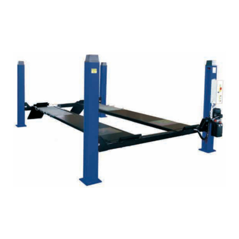
SOLLEVATORE A 4
COLONNE
GB
4-POST LIFT
528C


Manuale di istruzioni per l’ uso e la
manutenzione dei
SOLLEVATORE ELETTROIDRAULICO
PER VEICOLI
Modello 528C
Matricola N°
Anno di costruzione
COSTRUTTORE:
OMA S.p.A.
Sede centrale: Via dell’Artigianato, 64
36045 LONIGO (VI) -ITALY
Telefono ++ / +444 / 436199
Telefax ++ / +444 / 436208
1° Emissione - 02/04/2008
CENTRO DI ASSISTENZA AUTORIZZATO:
Rev.3 . . . . . . . . . . . . . . . 23/07/2009
Instruction manual for using and maintaining
ELECTRO-HYDRAULIC LIFTS FOR VEHICLES
Model 528C
Serial No.
Year of manufacture
MANUFACTURER:
OMA S.p.A.
Head Office: Via dell’Artigianato, 64
36045 LONIGO (VI) -ITALY
Telefono ++ / +444 / 436199
Telefax ++ / +444 / 436208
1rd Edition - 02/04/2008
AUTHORIZED SERVICE CENTRE:
1

Indice
Imballaggio, trasporto
e stoccaggio Pag. 3
Introduzione Pag. 4
Cap.1 Descrizione della
macchina Pag. 6
Cap.2 Specifiche tecniche Pag. 9
Cap.3 Sicurezza Pag.15
Cap.4 Installazione Pag.22
Cap.5 Funzionamento ed uso Pag.34
Cap.6 Manutenzione Pag.35
Cap.7 Inconvenienti e rimedi Pag.38
Appendice A Informazioni
particolari Pag.39
Appendice B Parti di ricambio Pag.39
Contents
Packing, transport and storage Page 3
Introduction Page 4
Chapter 1 Description of the
machine Page 6
Chapter 2 Specifications Page 9
Chapter 3 Safety Page 15
Chapter 4 Installation Page 22
Chapter 5 Operating
principles and use Page 34
Chapter 6 Maintenance Page 35
Chapter 7 Troubleshooting Page 38
Appendix A Special notes Page 39
Appendix B Spare parts Page 39
2

IMBALLAGGIO, TRASPORTO E
STOCCAGGIO.
LE OPERAZIONI DI IMBALLAGGIO, SOLLEVA-
MENTO, MOVIMENTAZIONE, TRASPORTO E DI-
SIMBALLO DEVONO ESSERE AFFIDATE ESCLU-
SIVAMENTE A PERSONALE CHE SIA ESPERTO
IN TALI OPERAZIONI E CHE CONOSCA BENE IL
PONTE SOLLEVATORE ED IL PRESENTE MA-
NUALE
IMBALLAGGIO
Il ponte sollevatore viene spedito smontato nei seguenti pezzi:
Peso di un pezzo (Kg)
4 colonne 70
2 traverse 120
2 rampe di salita 40
2 fermaruote 4
2 pedane: lato comando 600
lato opposto 450
1 assieme centralina 30
Il ponte sollevatore viene spedito avvolto in un unico pacco confe-
zionato con una lastra di materiale termoretraibile e sigillato con
due regge metalliche (Fig.1).
Il peso medio del pacco è di circa 1900 Kg.
SOLLEVAMENTO E MOVIMENTAZIONE
I pacchi possono essere sollevati e spostati soltanto con carrelli
elevatori, mantenendo una distanza di almeno 90 cm tra i due
bracci della forca (Fig.1).
Sollevare un solo pacco per volta.
I mezzi scelti devono essere idonei al sollevamento e spostamento
in sicurezza, tenendo conto di dimensioni, peso, baricentro del
pacco, sporgenze, parti delicate da non danneggiare.
Fig.1 Imballo e spostamento
Non sollevare o spostare MAI il sollevatore mediante fascie o
imbracature per il sollevamento (Fig.2).
STOCCAGGIO
Gli imballi devono sempre essere conservati in luoghi coperti e
protetti a temperature comprese fra -10 °C e + 40°C. e non devono
essere esposti ai raggi diretti del sole.
IMPILAMENTO DEI PACCHI
E’ sempre sconsigliato in quanto il pacco non è previsto per l’impi-
lamento. La base stretta, il peso notevole e la consistenza dell’im-
ballo rendono problematico e delicato l’impilamento.
Qualora si rendesse necessario l’impilamento, occorre adottare
molte precauzioni e in particolare:
- non superare mai i due metri di altezza della pila;
- non fare mai pile di pacchi singoli, ma fare sempre pile di pacchi
a coppie incrociate tra loro, in modo da ottenere cataste con una
base più larga ed una certa stabilità; quindi provvedere a rendere
sicuro lo stoccaggio, utilizzando regge, legacci o altri mezzi idonei.
Nei cassoni dei camion, nei container, nei vagoni ferroviari si
possono impilare al massimo due pacchi, purchè vengano
reggiati tra loro e assicurati contro la caduta.
PACKING, TRANSPORT AND
STORAGE.
PACKING, LIFTING, HANDLING, TRANSPORTING
AND UNPACKING OPERATIONS MUST BE PER-
FORMED ONLY BY EXPERIENCED PERSONNEL
WITH APPROPRIATE KNOWLEDGE OF THE LIFT
AND AFTER READING THIS MANUAL
PACKING
The lift is shipped disassembled in the following units:
Unit weight (kg)
4 posts 70
2 crossbeams 120
2 vehicle ramps 40
2 wheel stops 4
2 platform: control side 600
opposite side 450
1 hydraulic power unit 30
The lift is shipped in a single pack enclosed by a sheet of heat
shrink material and restrained by two steel straps (fig.1).
The average weight of the pack is 1900 kg.
LIFTING AND HANDLING
The packs can be lifted and transported only using lift trucks,
and keeping the fork arm centres at least 90 cm apart (Fig.1).
Lift only one pack at a time.
The lifting equipment must be capable of lifting and moving the
packs in complete safety, bearing in mind the dimensions, weight
and centre of gravity of the pack, any protruding parts, and delicate
parts to protect from impact damage etc.
Fig.2 Packing and moving
NEVER attempt to hoist or transport the unit using lifting
slings (Fig.2).
STORAGE
The packs must be kept in a covered and protected area in a tem-
perature range of -10°C to +40°C. They must not be exposed to di-
rect sunlight.
STACKING THE PACKS
We advise against stacking because the packs are not designed
for this type of storage. The narrow base, heavy weight and large
size of the packs make stacking difficult and potentially dangerous.
If stacking is unavoidable, use all appropriate precautions:
- never stack to more than 2 metres in height;
- never make stacks of single packs, always stack pairs of packs in
a cross pattern so that the base is bigger and the resulting stack is
more stable; once the stack is complete, restrain it using straps, ro-
pes or other suitable methods.
A maximum of two packs can be stacked on lorries, in contai-
ners, and in railway wagons, on the condition that the packs
are strapped together and restrained to stop them falling.
3

APERTURA DEGLI IMBALLI
All’arrivo verificare che la macchina non abbia subito danni durante
il trasporto e che ci siano tutti i pezzi indicati nella lista di spedizio-
ne.
I pacchi devono essere aperti adottando tutte le precauzioni per
evitare danni alle persone (tenersi a distanza di sicurezza mentre
si aprono le regge) e danni ai pezzi della macchina (evitare cadute
di pezzi dal pacco durante l’apertura).
É necessario prestare particolare attenzione per non danneg-
giare la centralina oleodinamica, il quadro comando e il cilin-
dro montato sulla pedana.
ELIMINAZIONE DELL’IMBALLO
Il termoretraibile deve essere smaltito come rifiuto, secondo la nor-
mativa vigente per il riciclo dei materiali plastici nel paese di instal-
lazione del ponte sollevatore.
INTRODUZIONE
IATTENZIONE
Questo manuale è stato scritto per il personale di officina ad-
detto all’uso del sollevatore (operatore) e per il tecnico addet-
to alla manutenzione ordinaria (manutentore) pertanto, prima
di effettuare qualsiasi operazione sul sollevatore e/o sul suo
imballaggio, occorre leggere attentamente tutto il manuale,
poichè esso contiene informazioni importanti per:
- LA SICUREZZA DELLE PERSONE addette all’uso ed alla ma-
nutenzione ordinaria,
- LA SICUREZZA DEL SOLLEVATORE,
- LA SICUREZZA DEI VEICOLI sollevati.
CONSERVAZIONE DEL MANUALE
Il manuale è parte integrante del sollevatore e deve sempre ac-
compagnarlo, anche in caso di vendita.
Esso deve sempre essere conservato in vicinanza del ponte solle-
vatore, in luogo facilmente accessibile.
L’operatore ed il manutentore devono poterlo reperire e consultare
rapidamente in qualsiasi momento.
SI RACCOMANDA, IN PARTICOLARE, UNA LETTURA ATTENTA
E RIPETUTA DEL CAPITOLO 3, CHE CONTIENE IMPORTANTI
INFORMAZIONI E AVVISI RELATIVI ALLA SICUREZZA.
I ponti sollevatori sono stati progettati e costruiti rispettando quanto
segue:
LEGGI:
Direttive europee: 98/37/CE-2004/108/CE-2006/95/CE
NORME TECNICHE:
Norme europee: EN 1493/ EN 292-1/ EN 292-2
IMPIANTO ELETTRICO:
UNI EN 60204, CEI 64/8
OPENING THE PACKS
When the lift is delivered make sure that it has not been damaged
during transportation and that all the parts specified on the packing
list are effectively present.
Packs must be opened adopting all the precautions required to
avoid injury to persons (keep at a safe distance when cutting the
straps) or damage to parts of the machine (be careful that no parts
are dropped while you are opening the packing).
Take special care with the hydraulic power unit, the control
panel and the platform cylinder.
DISPOSAL OF PACKING MATERIAL
The heat shrink plastic sheeting must be disposed of as waste ma-
terial in conformity with the laws for recycling of plastics in the
country of installation of the lift.
INTRODUCTION
IWARNING
This manual has been prepared for workshop personnel ex-
pert in the use of the lift (operator) and technicians responsib-
le for routine maintenance (maintenance fitter); read the ma-
nual before carrying out any operation with the lift and/or the
packaging. This manual contains important information regar-
ding:
- THE PERSONAL SAFETY of operators and maintenance wor-
kers,
- LIFT SAFETY,
- THE SAFETY OF LIFTED VEHICLES
KEEPING THE MANUAL
The manual is an integral part of the lift , and must be always
kept with it , even in the case of sale of the unit.
The manual must be kept next to the lift, in an easily accessible
place.
The operator and maintenance staff must be able to locate and
consult the manual quickly and at any time.
ATTENTIVE AND REPEATED READING OF CHAPTER 3,
WHICH CONTAINS IMPORTANT SAFETY INFORMATION AND
WARNINGS, IS PARTICULARLY RECOMMENDED.
Lifts are designed and built in compliance with:
LAWS:
European directives: 98/37/CE-2004/108/CE-2006/95/CE
TECHNICAL STANDARDS:
European standards: EN 1493/ EN 292-1/ EN 292-2
ELECTRICAL SYSTEM:
UNI EN 60204, CEI 64/8
4

Il sollevamento, il trasporto, il disimballo, il montaggio, l’installazio-
ne e la messa in servizio, la taratura e le registrazioni iniziali, la
manutenzioneSTRAORDINARIA, la riparazione, la revisione, lo
spostamento e lo smantellamento del sollevatore devono essere
eseguiti dai tecnici specializzati dei RIVENDITORI AUTORIZZATI
o dei CENTRI ASSISTENZA AUTORIZZATI dal Costruttore (vede-
re centro assistenza autorizzato indicato nel frontespizio):
Il costruttore non risponde di alcun danno a persone, veicoli
od oggetti causati dagli interventi sopracitati se effettuati da
personale non autorizzato o da un uso improprio o non con-
sentito del ponte sollevatore
Per tutte queste attività vengono indicati, nel presente manuale,
soltanto gli aspetti (operativi e di sicurezza) che possono essere
utili anche all’operatore ed al manutentore per comprendere meglio
la struttura ed il funzionamento del sollevatore e per un suo miglio-
re utilizzo.
Per comprendere il linguaggio adottato nel presente manuale, l’o-
peratore deve possedere esperienza specifica nelle attività di offi-
cina, di assistenza, manutenzione e riparazione dei veicoli nonchè
la capacità di interpretare correttamente i disegni e le descrizioni ri-
portate nel manuale e la conoscenza delle norme antinfortunistiche
generali e specifiche vigenti nel paese in cui viene installato il sol-
levatore.
Gli stessi criteri valgono per la scelta del tecnico manutentore che
dovrà, inoltre, possedere le conoscenze tecniche specifiche e spe-
cialistiche (meccaniche, elettriche) necessarie per effettuare in si-
curezza gli interventi previsti nel manuale.
Nel testo del manuale troverete spesso le diciture “operatore” e
“manutentore” il cui significato è il seguente:
OPERATORE: persona addetta all’uso del sollevatore.
MANUTENTORE: persona addetta alla manutenzione ordinaria del
sollevatore.
Lifting, transport, unpacking, assembly, installation and commissio-
ning, adjustment and initial set-ups, NON-ROUTINE maintenance,
overhauling, moving and taking down of the lift must always be
performed by qualified personnel from AUTHORISED DEALERS
or LICENSED SERVICE CENTRES (contact your licensed service
centre indicated on the title page of this manual):
The manufacturer will not be held liable for personal injury or
damage to vehicles or property caused by improper and/or
unauthorised use of the lift.
In respect of all the above mentioned activities, this manual covers
only such operational and safety aspects that are considered use-
ful for operators and maintenance personnel to gain a more com-
plete understanding of the structure and functions of the lift so that
it can be used in the best way.
To ensure adequate comprehension of the technical language in
this manual the operator must have specific experience of work-
shop procedures for servicing, maintenance and repair of vehicles
and must also be capable of interpreting the drawings and descrip-
tions in the manual and be aware of general and specific accident
prevention regulations in force in the country of installation.
The same considerations apply to the maintenance fitter who must
also possess specific technical (mechanical and electrical) skills
necessary to perform the various interventions described in the
manual in conditions of total safety.
The words “operator” and “maintenance fitter” are used with the fol-
lowing meaning in the manual:
OPERATOR: person in charge of using the lift.
MANUTENANCE FITTER: person in charge of routine maintenan-
ce of the lift.
5

CAP.1. DESCRIZIONE DELLA
MACCHINA
I ponti sollevatori a 4 colonne sono fissi, cioè ancorati al suolo;
sono progettati e costruiti per il sollevamento e lo stazionamento in
quota di autoveicoli e furgoni.
Sono composti principalmente da una parte fissa, ancorata al ter-
reno (colonne) e da una parte mobile (traverse e pedane di soste-
gno e sollevamento).
Il funzionamento è di tipo elettroidraulico.
Questi sollevatori sono composti, fondamentalmente da quattro
parti:
- gruppo struttura fissa;
- gruppo struttura mobile;
- gruppo di sollevamento;
- sicurezze.
In figura 3 sono indicate le varie parti che compongono il sollevato-
re e le zone di lavoro attorno al sollevatore stesso.
Lato operatore: è il lato anterioredel sollevatore, quello che com-
prende anche la zona riservata all’operatore in cui si accede al
quadro comandi ed è opposta al lato di ingresso del sollevatore.
Lato posteriore: è il lato opposto a quello operatore in cui si trova-
no le rampe di accesso al sollevatore.
Lati destro e sinistro: sono stabiliti rispetto all’operatore rivolto ver-
so il sollevatore.
Zona di rischio: è la zona di rischio in cui non si deve mai sostare
quando il sollevatore è in funzione; spiegazioni maggiormente det-
tagliate le troverete nel capitolo 3 “Sicurezze”.
La numerazione in figura 3 si riferisce a:
1 colonna lato comando (si intende per
convenzione interna come anteriore destra)
2 colonna anteriore sinistra
3 colonna posteriore sinistra
4 colonna posteriore destra
5 traversa lato comando (traversa anteriore)
6 traversa traversa posteriore
7 pedana destra, fissa
8 pedana sinistra, mobile
Fig.3
CHAPTER 1. DESCRIPTION
OF THE MACHINE
Four-post lifts are fixed installations, i.e. anchored to the floor; the
units are designed and built for lifting cars and vans and holding
them in an elevated position.
The units are essentially made up of a fixed part that is anchored
to the floor (posts) and a moving part (cross-pieces and platforms).
The operation is electro-hydraulic
There are four basic parts of the lifts:
- fixed structure assembly;
- movable structure assembly;
- lifting assembly;
- safety devices.
Figure 3 shows the various parts of the lift and the operating zones
in the surrounding area.
Operator side: this is the front of the lift, including the area reser-
ved for the operator with the control panel. The operator side is op-
posite the vehicle access side.
Rear side: it is the side opposed the operator’s one, with the lift ac-
cess ramps.
Right and left sides: the right and left is considered from the opera-
tor’s standpoint when facing the lift.
Danger zone: an area that must be kept clear of persons when the
lift is in use; refer to “Safety devices” chapter 3 for details.
Key to figure 3:
1 control side post (conventionally the front right-hand post)
2 front left post
3 rear left post
4 rear right post
5 control side cross-piece (front cross-piece)
6 rear cross-piece
7 right fixed platform
8 left moving platform
6
1
5
7
8
4
36
2
Zona operatore
Operator zone

GRUPPO STRUTTURA FISSA
E’ costituita da quattro colonne verticali in lamiera di acciaio piega-
ta alla cui base è saldata una piastra forata che permette il fissag-
gio al suolo mediante tasselli ad espansione (vedere capitolo 4 “
installazione”).
All’interno di ogni colonna sono alloggiati:
- un’asta di sicurezza con asole (1) per l’appoggio dei martelletti di
sicurezza,
- una fune in acciaio per il sollevamento (2),
- una guida per lo scorrimento verticale delle traverse.
Fig.4 Colonna
Fig.4 Post
Sulla sommità di ogni colonna sono ancorate:
- l’estremità dell’asta di sicurezza (4), (fissata con dado e controda-
do M20, classe di resistenza 8.8) ;
- l’estremità della fune in acciaio (5), che ha un codulo filettato M20
(fissato con dado e controdado M20, classe di resistenza 6S).
La lunghezza del codulo filettato consente la perfetta registrazione
delle funi, o la ripresa di un loro eventuale allungamento.
Alla colonna comando (Fig. 6) sono fissati il quadro elettrico di co-
mando e il deviatore idraulico
Sul pannello del quadro elettrico di
comando sono installati:
- l’interruttore generale (1);
- il pulsante di avvio (13);
- il pulsante di salita (2);
- il pulsante di stazionamento (4);
- il pulsante di discesa (3);
La centralina idraulica è composta
da:
- un motore elettrico (5)
- una pompa idraulica ad ingranaggi
(6)
- un’elettrovalvola di discesa (7)
- una vite di messa in scarico ma-
nuale del ponte (12)
- una valvola di massima pressione
(8),
- un serbatoio olio (9)
- un tubo flessibile di mandata olio
(10)
- un tubo flessibile per il recupero
dell’olio (11)
NOTA:
Il tubo di mandata olio (10) può tro-
varsi in pressione.
Il tubo di recupero olio (11) non è
mai in pressione.
Fig.6 Pannello di comando e centralina
idraulica.
FIXED STRUCTURE ASSEMBLY
The structure includes the four vertical posts in bent steel plate
with a pre-drilled baseplate for expansion anchors to secure the
unit to the floor (see chapter 4 “Installation”).
Each post houses:
- a safety rod with slots (1) to engage the safety wedges,
- a steel cable for lifting (2),
- a guide for the cross-piece vertical sliding (3).
Fig.5 Sommità colonne
Fig.5 Post top
The following parts are anchored to the top of each post:
- end of safety rod (4), (secured with M20 nut and lock nut, class
8.8);
- the end of the steel cable (5), which is fitted with an M20 threa-
ded shank (fixed with M20 nut and lock nut, class 6S).
The length of the cables can be perfectly adjusted - also to take up
slack due to stretching, thanks to the length of the threaded shanks
on the ends of the cables.
The drive post (Fig.6) mounts the electrical control panel and the
hydraulic power unit.
The following components are pre-
sent on the control panel:
- main switch (1);
- start button (13);
- lifting button (2);
- parking button (4);
- lowering button (3);
The hydraulic power unit comprises:
- motor (5)
- hydraulic gear pump (6)
- lowering solenoid valve (7)
- manual lowering screw (12)
- relief valve (8)
- oil reservoir (9)
- oil delivery hose (10)
- oil drain hose (11)
NOTE:
The delivery hose (10) is sometimes
pressurised;
the drain hose (11) is never pressu-
rised.
Fig.6 Control panel and hydraulic power
unit.
7
1
2
3
4
5
1
4
2
5
8
6
9
3
7
10
11
13
12

GRUPPO STRUTTURA MOBILE
É costituito da due traverse e da due pedane.
Ogni traversa scorre verticalmente tra due colonne.
Come si vede in fig.7, alle due estremità di ogni traversa sono fis-
sati:
- le pulegge di rinvio (1) della fune di sollevamento,
- gli innesti meccanici di sicurezza (martelletti) (2 e 3).
Il martelletto di stazionamento (pos.3) si inserisce automaticamen-
te durante tutta la fase di salita e nello stazionamento. Deve esse-
re disinserito elettricamente durante la fase di discesa.
In caso di rottura della fune, si azio-na il microinterruttore funi (4)
che provoca il blocco della parte elettrica del ponte e l’inserimento
del martelletto di stazionamento, pertanto della sua parte mobile
nonchè del carico.
Le due pedane portaveicoli (Fig. 9) appoggiano sulle traverse.
La pedana sinistra (1) è fissa, mentre la pedana destra (2) è mobi-
le e può scorrere orizzontalmente per adattarsi alle diverse carreg-
giate dei veicoli. Entrambe sono dotate di bordi interni (3) di conte-
nimento dei pneumatici del veicolo e di arresti fissi di sicurezza (4)
che impediscono al veicolo stesso di oltrepassare accidentalmente
la fine della pedana; le rampe di accesso (5), incernierate sulle pe-
dane, si posizionano verticalmente quando le pedane salgono,
bloccando in maniera definitiva il veicolo.
Fig.9 Pedane e Traverse
All’interno della pedana lato co-
mando (Fig. 10), con accesso dal
solo lato inferiore (lato suolo),
si trovano:
- il cilindro idraulico di sollevamen-
to (1);
- la valvola paracadute o di blocco
(2);
- il giogo di attacco (3) delle funi di
acciaio;
- due gruppi pulegge di rinvio (4)
delle funi.
Fig.10- Interno pedana fissa
MOVABLE STRUCTURE
The movable structure consist of two cross-pieces and two plat-
forms.
Each cross-piece translates vertically between two posts.
As shown in fig.7, the ends of the cross-pieces are fitted with the
following parts:
- return pulleys (1) for the lift cable,
- mechanical safety devices (wedges) (2 and 3).
The wedge (pos. 3) will engage automatically during lifting and
when the lift is raised.
In case of breakage of the cable, the cable micro switch (4) causes
the lock of the lift electrical part and the engagement of the safety
wedge, therefore it stops the movable part and the relevant vehic-
le.
The two platforms (Fig. 9) are supported on the cross-pieces.
The left platform (1) has no adjustment; the right platform (2) is
free to slide across the width of the lifting area to adapt to the track
width of the vehicle being lifted.
Both platforms have inside kerbs (3) to keep the vehicle tyres fully
on the lifting surface, and fixed wheel stops (4) to stop the vehicle
from going beyond the ends of the platforms;
The access ramps (5), pivoted to the platforms, automatically re-
ach a vertical position when the platforms lift, thereby securing the
vehicle also from the access end.
Fig.9 Platforms and cross-pieces
The following components are loca-
ted beneath the fixed platform (Fig.
10), and are accessible only from
underneath:
- hydraulic lift cylinder (1);
- parachute safety valve (2);
- clevis coupling (3) for the steel
cables;
- two cable return pulley assemblies
(4).
FiIg.10 Interior of the fixed platform
8
Fig.8
Abb.8 4
1
3
1
3
2
3
2
3
1
4
4
Fig.7
Abb.7 4
1
3

CAP.2. SPECIFICHE TECNICHE
PORTATA: ................................................8000 kg (78400 N)
Alt. max. sollevamento auto ......................2000mm
Alt. min. supporti sollevamento .................190 mm
Interasse longitudinale colonne.................5920mm
Interasse trasversale colonne ...................3480mm
Larghezza libera tra colonne.....................3300mm
Larghezza pedane ...................................650 mm
Lunghezza pedane ...................................6200mm
Tempo di salita . . . ...................................55 sec
Tempo di discesa . ...................................55 sec.
FUNE di sollevamento in acciaio, con le seguenti caratteristiche:
Diametro . . . . . . . . ...................................11 mm
Numero di fili . . . . . ...................................227
Resistenza dei fili . ...................................1960 N
Diametro primitivo pulegge .......................220 mm
Rumorosità . . . . . . 70dB(A)/1m
PESO totale del sollevatore .....................circa 1820 Kg
Temperatura di funzionamento .................-10°C / + 50°C
Pressione di lavoro ....................................160 bar
Ambiente di lavoro: locale chiuso.
MOTORE ELETTRICO
Tipo . . . . . . . . . . . . C90
Potenza. . . . . . . . . 3 KW
Tensione
230-400V trif. +/-5%
Frequenza. . . . . . . 50 Hz
N° poli . . . . . . . . . . 4
Velocità . . . . . . . . . 1400 giri/1’
Forma costruttiva . B 14
Classe isolamento. F
Assorbimento . . . . 230V: 15A
. . . . . . . . . . . . . . . 400V: 8,7A
Il collegamento del motore deve
essere eseguito riferendosi agli
schemi elettrici allegati.Il senso
di rotazione del motore è sinistro
(antiorario) come indicato nella
targhetta applicata sul motore
stesso.
Fig.11 Dimensioni ed ingombri
POMPA
Tipo . . . . . . . . . . . . ...................................20
Modello . . . . . . . . . ...................................10A7,4X348N
Cilindrata. . . . . . . . ...................................7,4 cm3 /g
Taratura valvola di massima...............................160 bar
CHAPTER 2 SPECIFICATIONS
CAPACITY: ...............................................8000 kg (78400 N)
Max. vehicle lifting height ..........................2000mm
Min. ground clearance of lift structure .......190 mm
Longitudinal C/C distance between posts . 5920mm
Transverse C/C distance between posts... 3480mm
Effective clearance between posts............ 3300mm
Platform width . . . . ................................... 650mm
Platform length . . . ...................................6200mm
Lift time . . . . . . . . . ..................................55 sec
Lowering time . . . . ..................................55 sec
LIFTING CABLES in steel, having the following features:
Diameter . . . . . . . . ...................................11 mm
Strands . . . . . . . . . ...................................227
Tensile strength of strand..........................1960 N
Pulley pitch diameter.................................220 mm
Noise. . . . . . . . . . . 70dB(A)/1m
OVERALL WEIGHT of lift unit...................1820 kg approx.
Working temperature range.......................-10°C / + 50°C
Working pressure ......................................160 bar
Installation requirements: enclosed area.
MOTOR
Type ...........C90
Power .........3 kW
Voltage
230-400V th.-ph. +/-5%
Frequency ..50 Hz
Poles ..........4
Speed.........1400 rpm
Building shape .....B 14
Insulation class ....F
Absorption ..230V: 15A
...................400V: 8,7A
When connecting the motor refer
to the enclosed wiring diagrams.
The motor has left-handed rotation
(counter-clockwise) as shown on
the data plate on the casing.
Fig.11 Overall dimensions and clearances
PUMP
Type . . . . . . . . . . . ...................................20
Model . . . . . . . . . . ...................................10A7,4X348N
Displacement . . . . ...................................7,4 cc/rev.
Relief valve set-up ...................................160 bar
9

CENTRALINA OLEODINAMICA
La centralina oleodinamica, ovvero le parti, componenti la pompa,
che traducono il movimento del motore in spinta dell’olio nei tubi
(figura 12).
Fig.12- Centraline
OLIO
Il serbatoio dell’olio contiene olio idraulico a base minerale secon-
do normativa ISO/DIN 6743/4 con grado di contaminazione non
superiore alla classe 18/15 secondo normativa ISO 4406 come IP
HYDRO OIL 32; SHELL TELLUS T 37 o equivalenti.
HYDRAULIC POWER UNIT
The hydraulic power unit, i.e. the various components of the pump
that convert the rotary motion of the motor into fluid pressure for
the hydraulic circuit (Figure 12).
Fig.12 - Hydraulic power units
OIL
The hydraulic oil reservoir is filled with mineral oil to ISO/DIN
6743/4, contamination category no higher than class 18/15 accor-
ding to ISO 4406, such as IP HYDRO OIL 32; SHELL TELLUS T
37 or an equivalent oil.
10
Carico olio
Delivery
Valvola massima pressione
Relief valve
Tubo per recupero olio
Drain hose
Elettrovalvola
Solenoid valve Valvola regolatrice di scarico
Outlet adjusting valve
Scarico manuale
Outlet manual
Valvola di ritegno
Check valve

SCHEMI ELETTRICI ED OLEODINAMICI WIRING DIAGRAMS AND HYDRAULIC
11

LEGENDA SCHEMA ELETTRICO WIRING DIAGRAMS KEY
12
Rif.
Ref.
Descrizione Description Marca
Brand
Articolo
Article
Q.tà
Q.ty
C1-C2 Elettromagnete Electromagnet E0425 24V CC 50Hz 2
C3 Elettrovalvola Solenoid valve OIL SISTEM 24VAC 50/60Hz ED100% 1
FU1 Portafusibile 10x38 Fuse carrier 10x38 WEBER PCH10x38+CH10x38 2
F1 Portafusibile 5x20 Fuse carrier 5x20 Integrato nella scheda / Integrate in the electric board 1
PTC Protezione termica Thermal limiter Integrato nel motore / Integrate in the motor 1
QM1-QM4 Microinterruttori funi Cable microswitch PIZZATO FR1454 4
QM5 Microinterruttore salita Lifting microswitch PIZZATO FR654 1
QM11 Microinteruttore discesa Lowering microswitch PIZZATO FR754 1
QS Interruttore generale Master switch SPRECHER LA2-16-1754+LFS2-N-6-175+
LA2-12-C4+LA2-G2853+LA2-G3195
1
KM1 Teleruttore Motor contactor 24V 50/60Hz 1
K1 Relè elettromagneti Electromagnet relay FINDER 55.32.9.024.0040 1
KA2 Relè discesa Lowering relay FINDER 55.34.9.024.0040 1
KA3 Relè salita Lifting relay Integrato nella scheda / Integrate in the electric board 1
KA4 Relè primario
trasformatore
Primary transformer
relay
FINDER 55.34.9.024.0040 1
KT1 Relè TR1 (elettromagneti) Relay TR1 (electroma-
gnet )
Integrato nella scheda / Integrate in the electric board 1
KT2 Relè TR2 (discesa) Relay TR2 (lowering) Integrato nella scheda / Integrate in the electric board 1
TR1 Trimmer KT1 (elettroma-
gneti)
Trimmer KT1 (electro-
magnet )
Integrato nella scheda / Integrate in the electric board 1
TR2 Trimmer KT2 (discesa) Trimmer KT2 (lowe-
ring)
Integrato nella scheda / Integrate in the electric board 1
M Motore elettrico Electric motor 230/400V 50Hz 1
SB1 Pulsante salita Lifting button 1 NO 1
SB2 Pulsante discesa Lowering button 2 NO 1
SB3 Pulsante stazionamento Parking button 2 NO + 1 NC 1
SB8 Pulsante inserzione
macchina
Machine connection
button
2 NO 1
FR2 Interruttore
magnetotermico
Magnetic switch 20A TYPE C 1
BZ1 Avvisatore acustico
salvapiedi
Warning siren Integrato nella scheda / Integrate in the electric board 1
TM Trasformatore Transformer C.E. 230-400/24V 300VA 50/60Hz 1
SCHEDA ELETTRICA ELECTRIC BOARD
VERIFICARE L’ESATTA POSIZIONE DEI RELE’ CHECK THE CORRECT RELAYS POSITION

SCHEMA TOPOGRAFICO
IATTENZIONE
I cavi contrassegnati con colore Giallo possono essere in al-
ternativa anche di colore Grigio.
TOPOGRAPHIC DIAGRAM
IWARNING
The marked cables with Yellow color could be in alternative
also of Grey color.
13
Elettromagnete
Electromagnet
Quadro elettrico
Control panel
Micro funi
Cable micro-switch
Marrone - Braun
Blu - Blau
Marrone - Braun
Blu - Blau
Micro funi
Cable micro-switch
Micro funi
Cable micro-switch
Micro funi
Cable micro-switch
Elettromagnete
Electromagnet
Giallo - Yellow
Nero - Black
Giallo -Yellow
Nero - Black
Giallo - Yellow
Nero - Black
Giallo -Yellow
Nero - Black Giallo -Yellow
Nero - Black
Marrone - Braun
Blu - Blau
Marrone - Braun
Blu - Blau
Marrone - Braun
Blu - Blau
Rosso 5 - Red 5
Nero 0 - Black 0
Rosso 6 - Red 6
Nero 0 - Black 0
Marrone -
Braun
Blu - Blau
Giallo - Yellow
Nero - Black

SCHEMA OLEODINAMICO
Rif. Descrizione
1 Valvola paracadute
2 Elettrovalvola
3 Valvola di ritegno
4 Valvola di massima
5 Valvola di strozzamento
6 Motore
7 Pompa
8 Filtro
9 Serbatoio
HYDRAULIC CIRCUIT DIAGRAM
Re. Description
1 Parachute valve
2 Solenoid valve
3 Check valve
4 Relief valve
5 Throttle valve
6 Motor
7 Pump
8 Filter
9 Reservoir
14
Motore + protezione termica motore - Motor and thermal switch (8-9)
Elettromagneti - Electromagnet
Microinterruttori fune and ON/OFF switch for broken or slacken rope (0-2) (1-2)
Finecorsa - Limit switch (3-4)
Elettrovalvola - Solenoid valve (0-7)
Microinterruttore discesa QM11 - LOWERING microswitch QM11 (1-17) (16-18)
1
4
7
2
5
3
6
8
9
2
1
Azzurro
Blue sky
16
Nero
Black
17
Marron
Brown
18
Grigio
Grey
NC
NO
21 22
13 14
QM11

TIPI DI VEICOLI SOLLEVABILI E INGOMBRI
I ponti sollevatori si adattano praticamente a tutti i veicoli di peso
non superiore a 8000 kg e le cui dimensioni non eccedano quelle
riportate di seguito.
DIMENSIONI MASSIME DEI VEICOLI DA SOLLEVARE
La larghezza non deve eccedere i 2500 mm.
Il passo tra gli assi non deve eccedere i 5000 mm.
La distanza massima tra i bordi esterni dei pneumatici, compreso il
rigonfiamento a terra, non deve eccedere i 2200mm.
La distanza minima tra i bordi interni dei pneumatici, compreso il ri-
gonfiamento a terra, non deve essere inferiore a 1000mm.
L’ altezza minima da terra può interferire con le strutture del solle-
vatore.
Fare attenzione soprattutto alle autovetture sportive.
Eventuali carrozzati speciali possono essere sollevati tenendo
però conto della portata del sollevatore.
Anche la zona di rischio per le persone dovrà essere adeguata
alle dimensioni speciali del veicolo.
Gli schemi seguenti riportano i criteri per definire i limiti di impiego
del sollevatore.
Fig.13 Misure minime e massime
PER INGOMBRI MAGGIORI VERIFICARE IL CARICO MASSIMO
ED IL SUO SBILANCIAMENTO
PESI MASSIMI DEI VEICOLI DA SOLLEVARE
Fig.14 Ripartizione pesi “A”
Fig.14 Weight distribution “A”
TYPES OF VEHICLES SUITABLE FOR BEING LIFTED AND
OVERALL DIMENSIONS
Lifts are suitable for virtually all vehicles with total weight of no
more than 8000 kg and with dimensions not exceeding the below
data.
MAXIMUM DIMENSIONS OF VEHICLES MAIN LIFTED
Max. width: 2500 mm.
Max. wheelbase: 5000 mm.
Max. distance between outer wall of tyres, inclusive of bulge cau-
sed by weight of vehicle on ground: 2200 mm.
Min. distance between inner walls of tyres, inclusive of bulge cau-
sed by weight of vehicle on ground: 1000mm.
Caution: the lower parts of the vehicle underbody could interfere
with structural parts of the lift.
Take particular care in the case sports-cars.
The lift will also handle customised or non-standard vehicles provi-
ded they are within the maximum specified carrying capacity.
Also the personnel danger zone must be defined in relation to
vehicles with unusual dimensions.
The following diagrams illustrate criteria used to define the opera-
ting limits of the lift.
Fig.13 Maximum and minimum dimensions
FOR LARGER DIMENSIONS CHECK THE MAXIMUM LOAD
AND POSSIBLE UNBALANCE
MAXIMUM WEIGHTS OF VEHICLES BEING LIFTED
Fig.15 Ripartizione pesi “B”
Fig.15 Weight distribution “B”
15
A
B
C
D
Min. (mm) Max. (mm)
A- 5000
B100 -
C- 2200
D1000 -
E- 2500
E

CAP.3 SICUREZZA
É estremamente importante leggere questo capitolo attenta-
mente ed in ogni sua parte poichè contiene importanti infor-
mazioni sui rischi che operatore e manutentore possono cor-
rere in caso di un uso errato del ponte sollevatore.
Nel testo che segue troverete chiare spiegazioni su alcune si-
tuazioni di rischio o pericolo che si possono verificare durante
l’uso e la manutenzione del sollevatore, sui dispositivi di sicu-
rezza adottati e sul loro uso corretto, sui rischi residui e sui
comportamenti da tenere (precauzioni generali e specifiche
per eliminarli o neutralizzarli).
IATTENZIONE:
I sollevator sono stati progettati e costruiti per il
sollevamento e lo stazionamento in quota dei vei-
coli in ambiente chiuso. Ogni altro uso non è con-
sentito ed in particolare essi non sono idonei per
operazioni di:
- lavaggio e verniciatura;
- ponteggio o sollevamento di persone;
- pressa per schiacciare;
- montacarichi;
- CRIC per sollevare o cambiare ruote.
Il costruttore non risponde di alcun danno a per-
sone, veicoli od oggetti causati dall’uso improprio
o non consentito dei ponti sollevatori
In fase di salita o discesa l’operatore deve agire
soltanto dalla postazione di comando indicata in
Fig.16.
É vietato a chiunque sostare sotto le traverse e/o
le pedane in movimento o sostare entro la zona di
rischio indicata in Fig.16.
Si definisce come “ZONA DI RISCHIO” tutta l’area
occupata dal sollevatore comprensiva della fascia
perimetrale del sollevatore di larghezza 1÷2 mt.
Si definisce come “ZONA OPERATORE” l’area in
cui è prevista la sosta dell’operatore solo per
l’azionamento del sollevatore.
In fase di lavoro la presenza di persone sotto il
veicolo è ammessa soltanto quando il veicolo è
già sollevato, le traverse e le pedane sono ferme e
le sicurezze meccaniche (martelletti) sono inseri-
te nelle asole delle aste di sicurezza.
IATTENZIONE:
LA PRESENZA DI PERSONE SOTTO IL VEICOLO
SOLLEVATO E’ AMMESSA SOLTANTO QUANDO
IL SOLLEVATORE E’ IN STAZIONAMENTO SUI
MARTELLETTI DI SICUREZZA.
NON UTILIZZARE LA MACCHINA SENZA LE
PROTEZIONI O CON LE
PROTEZIONI
DISATTIVATE.
IL MANCATO
RISPETTO DI QUESTE
NORME PUO’ RECARE
GRAVI DANNI ALLE
PERSONE, AL
SOLLEVATORE ED AI
VEICOLI SOLLEVATI.
Fig.16
CHAPTER 3 SAFETY
It is extremely important to read this chapter of the manual ca-
refully and from beginning to end as it contains important in-
formation regarding the risks the operator or maintenance fit-
ter may be exposed to if the lift is used incorrectly.
In the following text there are clear explanations regarding
certain situations of risk or danger that may arise during the
operation or maintenance of the lift, the safety devices instal-
led and the correct use of such systems, residual risks and
operative procedures to use (general and specific precautions
to eliminate potential hazards).
IWARNING:
Lifts are designed and built to lift vehicles and
hold them in the elevated position in an enclosed
workshop. All other uses of the lifts are unautho-
rised. In particular, the lifts are not suitable for:
- washing and respray work;
- creating raised platforms for personnel or lifting personnel;
- use as a press for crushing purposes;
- use as elevator;
- use as a lift jack for lifting vehicle bodies or changing wheels.
The manufacturer is not liable for any injury to
persons or damage to vehicles and other property
caused by the incorrect and unauthorised use of
the lifts.
During lifting and lowering movements the opera-
tor must remain in the control station as defined
in figure 16.
The presence of persons beneath the cross-pie-
ces and/or the platforms when they are moving,
or the presence of persons inside the danger
zone indicated in figure 16 is strictly prohibited.
The area occupied from the lift and perimetral
band of width 1÷2 mt of the lift are defined as
"DANGER ZONE".
The operator parking area, only for actioning the
lift, is defined as "OPERATOR ZONE".
During operations persons are admitted to the
area beneath the vehicle only when the vehicle is
already in the elevated position, when the
cross-pieces and platforms are stationary, and
when the mechanical safety devices (wedges) are
firmly engaged in the slots on the safety rods.
IWARNING:
THE PRESENCE OF PERSONS BENEATH THE
VEHICLE IS PERMITTED ONLY WHEN THE LIFT
IS IN THE PARKING POSITION ON THE SAFETY
WEDGES.
DO NOT USE THE LIFT
WITHOUT PROTECTION
DEVICES OR WITH THE
PROTECTION DEVICES
INHIBITED.
FAILURE TO COMPLY WITH
THESE REGULATIONS CAN
CAUSE SERIOUS INJURY
TO PERSONS, AND IRREPA-
RABLE DAMAGE TO THE
LIFT AND THE VEHICLE
BEING LIFTED.
16
Zona di rischio
Danger zone
Zona operatore
Operator zone

PRECAUZIONI GENERALI
L’operatore ed il manutentore sono tenuti al rispetto delle prescri-
zioni contenute in leggi e norme antinfortunistiche vigenti nel pae-
se in cui è installato il sollevatore.
Devono inoltre:
- operare sempre dalle postazioni di lavoro previste ed indicate nel
manuale;
- non rimuovere nè disattivare i carter e le protezioni meccani-
che,elettriche, o di altra natura;
- prestare attenzione agli avvisi di sicurezza riportati nelle targhette
applicate sulla macchina e nel manuale .
Nel testo del manuale gli avvisi di sicurezza saranno evidenziati
nelle forme seguenti:
PERICOLO: Indica un pericolo imminente che può causare danno
alle persone (gravi lesioni o anche la morte).
ATTENZIONE: Indica situazioni e/o comportamenti rischiosi che
possono causare danni alle persone (lesioni più o meno gravi e/o
anche la morte).
CAUTELA: Indica situazioni e/o comportamenti rischiosi che pos-
sono causare danni di minore gravità alle persone e/o danni al sol-
levatore, al veicolo o ad altre cose.
RISCHIO DI FOLGORAZIONE: è un particolare avviso di sicurez-
za che viene riportato sul sollevatore, tramite targhetta, in alcuni
punti dove è particolarmente elevato il rischio di forti scosse elettri-
che.
RISCHI E PROTEZIONI
Vediamo ora quali rischi possono correre gli operatori o il manuten-
tore in fase di stazionamento del veicolo sulle pedane e quali pro-
tezioni sono state adottate dal costruttore per ridurre al minimo tali
rischi:
SPOSTAMENTI LONGITUDINALI
Gli spostamenti longitudinali sono i movimenti in avanti o
all’indietro del carico.
Come protezione sono stati applicati dei fermi fissi (1) sul lato an-
teriore e dei fermi basculanti (2), integrati con le pedane che, du-
rante la salita e nello stazionamento, bloccano il veicolo impeden-
dogli ogni movimento pericoloso.
Fig.17 Spostamento longitudinale e protezione
GENERAL PRECAUTIONS
The operator and the maintenance fitter are required to observe
the prescriptions of safety regulation in force in the country of in-
stallation of the lift.
Furthermore, the operator and maintenance fitter must:
- always work in the stations specified and illustrated in this ma-
nual;
- never remove or deactivate the guards and mechanical, electri-
cal, or other types of safety devices;
- read the safety notices placed on the machine and the safety in-
formation in this manual.
In the manual all safety notices are shown as follows:
DANGER: indicates imminent danger that can result in serious in-
jury to people or death.
WARNING: indicates situations and/or types of manoeuvres that
are unsafe and can cause more or less harmful injuries or death.
CAUTION: indicates situations and/or types of manoeuvres that
are unsafe and can cause minor injury to persons and/or damage
the lift, the vehicle or other property.
RISK OF ELECTRIC SHOCK: a specific safety notice placed on
the lift in areas where the risk of electric shock is particularly high.
RISKS AND PROTECTION DEVICES
We shall now examine the risks that operators or maintenance fit-
ters may be exposed to when the vehicle is standing on the plat-
forms in the raised position, together with the various safety and
protection devices adopted by the manufacturer to reduce all such
hazards to the minimum:
LONGITUDINAL MOVEMENTS
Longitudinal movements refer to forward and backward movement
of the load (vehicle).
To protect against the consequences of longitudinal movement we
have installed fixed wheel stops (1) at the front of the lift, and pivo-
ting stops (2) at the rear. The stops are integral with the platforms
and serve to secure the vehicle during lifting and lowering move-
ments and when the vehicle is at a standstill in the raised position,
thus preventing any potentially dangerous movement.
Fig.17 Longitudinal movement and safety systems
17
1
2

SPOSTAMENTI LATERALI
Per una sicurezza ottimale delle persone e dei mezzi è importante
che:
- si rispetti la zona di rischio durante il sollevamento (vedere
Fig.16),
- il motore del veicolo sia spento, la marcia innestata, ed il freno a
mano tirato,
- il veicolo sia posizionato in maniera corretta (vedere Fig.19);
- vengano sollevati soltanto veicoli ammessi, senza superare mai
la portata, gli ingombri in altezza e le sporgenze (lunghezza e lar-
ghezza del veicolo);
- non vi siano persone sulle pedane durante il sollevamento e lo
stazionamento (Fig.19).
Fig.19 Veicolo caricato correttamente
SIDE MOVEMENTS
For optimal personal safety and safety of vehicles, observe the fol-
lowing regulations:
- do not enter the danger zone while vehicles are being lifted (see
Fig.16),
- switch off the engine of the vehicle, engage a gear and engage
the hand brake,
- make sure the vehicle is positioned correctly (see Fig.19);
- be sure to lift only approved vehicles, never exceed the specified
carrying capacity, maximum height, and projections (vehicle length
and width);
- make sure that there are no persons on the platforms during up
and down movements and during standing (Fig.19).
Fig.19 Correctly positioned vehicle
18
Table of contents
Other OMA Lifting System manuals
Popular Lifting System manuals by other brands

R. Beck Maschinenbau
R. Beck Maschinenbau HS 1200 FH operating manual

Skyjack
Skyjack SJ 3215 Operation manual

THIEMAN
THIEMAN NTEA TVL Series installation instructions

Pro-Lift
Pro-Lift PL5500 Operating instructions & parts manual

Walker Magnetics
Walker Magnetics NEO-1000 Operation manual

Harsh
Harsh HS10T Operator's manual