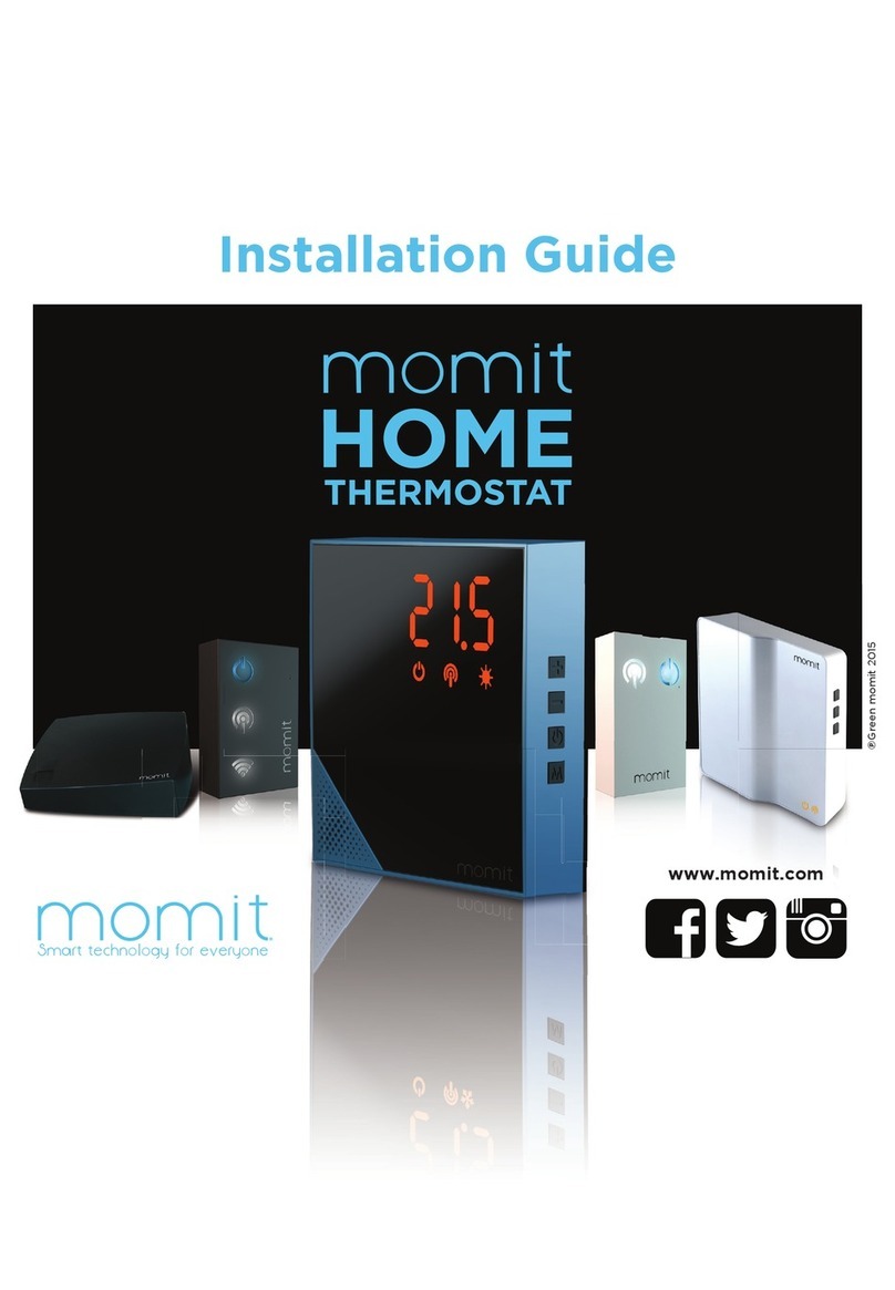
momit Home User manual

Installation
guide

2
Index
momit Home System
Products presentation
Characteristics
Possible congurations
Installation
Additional content
Gateway
Thermostat
Extension Kit
Customise your device
3
4
5
8
9
10
11
12
15
19

3
momit Home System

4
The momit Home system is made up of 3 devices:
- Gateway
- Thermostat
- Extension Kit*
Gateway Thermostat Extension Kit
Products presentation
*Sold separately

5
Characteristics
The Gateway is a device that is connected to Internet with
an Ethernet cable. It uses wireless 802.15.4 connectivity
technology to communicate with other momit Home
devices. The Gateway makes it possible for you to control
momit Home from your smartphone, tablet or computer
by means of the momit App.
Gateway
- Platform registration by means of QR code
- 5V power input (USB)
- Wireless: IEEE 802.15.4
- LED status display
- Ethernet interface
- CE
- RoHS
- Dimensions:
123 x 123 x 44 mm
- Weight: 150 g
Características:

6
Replace your old thermostat with a new
smart one. Easy to t, all you have to do
is to remove the current thermostat and
t the momit Home Thermostat.
Thermostat
- Easy to t
- Boiler control
- Temperature up/down, boiler on/off buttons
- iOS, Android, Windows Phone and Blackberry mobile APP
- Platform registration by means of QR code
- Power input 2 alkaline AA batteries
- Wireless: IEEE 802.15.4
- Temperature, humidity and presence sensor
- +-0.3ºC temperature accuracy
- LED display
- Relays:
2A at 30 VCC
0.5A at 125 VAC
- CE
- RoHS
- Dimensions: 100x100x25 mm
- Weight: 150 g
Characteristics:

7
- An On/Off boiler button
- Platform registration by means of QR code
- 110V/230V 50/60Hz power input
- Wireless: IEEE 802.15.4
- 12A relay
- LED display
- CE
- RoHS
- Dimensions: 103x107x27 mm
- Weight: 150 g
This device enables momit Home Thermostat to control
a boiler or underoor heating wirelessly.
Characteristics:
Extension Kit

8
This section deals with the different momit device
combinations to help you select the one that best
adapts to your home and needs. The possibilities
are as follows:
Boiler heating systems:
a) Gateway + Thermostat: This combination enables
you to control your home heating at all times no
matter where you are. The Gateway connects your
heating system to Internet. Accordingly, you can
control your thermostat by means of the momit App
over your smartphone, tablet or computer. You can
add as many thermostats as you like.
b) Gateway + Thermostat + Extension Kit: This
combination provides you with all the functions of the
previous option with the added advantage of being
able to control the boiler with a mobile device that
can be placed in any room in the house. You can add
as many thermostats as you like.
a)
b)
Possible congurations

9
Installation
Warning!
Read these instructions carefully before starting the
installation.
momit devices must be installed in accordance with
current regulations.
If you are going to install an Extension Kit, make sure
that the power has been cut off before proceeding
with the installation.

10
Extension Kit
Gateway Thermostat
Ethernet cable USB cable Power
adapter
2 AA 1.5V 2700
mAh alkaline
batteries
2 M3x30
screws
2 M3x30
screws
2 raw plugs
2 raw plugs
Additional content

11
You must connect this device rst. Follow these
steps to do so:
1. Connect it to the mains by means of the USB
cable (3).
Connecting to the Internet
Device connection indicator
Leds de estado
On/Off
5
4
2
3
1
Jack connector
On/Off
MicroUSB connector
Ethernet
Reset
1
2
3
4
5
Ethernet cable
Power cable
2. Connect the Ethernet cable (4) to the router in
your home.
3. Wait until the 3 status LEDs are on before
continuing with the installation.
Gateway

12
1. Remove the connection box at the back of the
thermostat (part B).
2. Insert the boiler connection wires through the
gap in the part.
Connection
box
Gap through which you
must insert the wires
A
B
4. Fit the connection wires as shown in the diagram:
Connection diagram
3. Screw the connection box to the wall. Use the
two screws that come in the pack to do so.
Thermostat
W
COM
W: boiler
COM: the common boiler

13
If the wire is rigid you can insert it directly.
When it is a exible wire you may need the help
of a punch or pen tip. Press as indicated in the
drawing (1) and insert the wire (2).
To remove it, rst
press and then pull
on the wire.
4. Insert two AA batteries.
AA batteries
1
2
6. After the thermostat is switched on it will
synchronise automatically with the Gateway.
This process may take less than a minute.
The device connection LED
will be on if everything is working properly. As
of now both devices have been connected.
5. Fit the thermostat
body (part A) into the
connection box (part B)
as shown in the following
drawing.
A
B
0.5-1.5mm
6-8mm 2

14
Raise the set temperature
Lower the set temperature
On/off mode
Brightness mode
1
2
3
4
1
2
3
4
Buttons
Status LEDs
Off
Update in progress
Gateway connection indicator
Heating consumption indication
Fit 1 m away
on both sides
1.5 m high Away from
sources of
cold and heat
Thermostat placement
1.5 m
1 m 1 m

15
2. Connect the relay wires to the corresponding
terminals, as per the connection diagram, to enable the
Extension Kit to control the boiler.
1. Insert the installation wires. You can do so in two
ways:
Case A:
If the power wires
come from the wall,
insert them as follows:
Case A Case B
Case B:
If the power wires come
from the boiler, insert
them as follows:
Extension kit
Connection diagram
12A relay:
W2C: common connector
W2: boiler connector
W2-: N/A
Power input:
L: Line
N: Neutral
W2C W2-
W1-
W1C
W1
W2
L
N
0.5-1.5mm
6-8mm 2

16
You are recommended to connect the power wires
at the end. Take safety measures when working
with electricity. Cut off the current in the area where
you are working until you have completed the
installation.
- Extension Kit requires 110 to 230 VAC input.
Connect up Land Nterminals.
- You can control a boiler with Extension Kit by
connecting the 2 control wires to W2 and W2C.
How to connect the wires:
It is recommended to keep the indicated
distance if you are tting it near the boiler.
30 cm

17
Make sure the power has been
cut off to the boiler when
undertaking these operations.
Identify the thermostat
terminals in the boiler manual.
They are normally indicated
with the following tags LS-
LR, TA or COM-NO. You can
also identify them by a branch
between the two thermostat
terminals, in which case you
must remove this branch.
Connect the boiler adapter wires
to where the branch is to be
found.
Identify
Thermostat terminal
LS-LR
TA
COM-NO
The Extension Kit requires 110 to 230 VAC
input.
The power terminals from the boiler usually
have L/N or P/N tags.
Power
110 to 230 VAC power input
terminals.
P/N
L/N

18
Device On/Off
Manual boiler control whenever there is no
Internet connection
Reset
1
2
3
Buttons
The device connection LED
will be on if everything is working properly.
The Extension Kit is connected to Gateway
as of that moment.
Status LEDs
Off
Device connection indicator
1
2
3

19
momit Home Thermostat has interchangeable frames. Follow these steps to change the frame:
1 2 3
Remove the cover and take out
the batteries.
Insert a pen into the hole under
the batteries.
Exert pressure until the front casing
comes away and pull it out.
Customise your device

20
4 5
Press the body of the thermostat backwards
while bringing the frame forward until it
comes out.
Position the new frame and, while in the
same position as in the previous step, push
the frame until it ts ush.
6 7
Push until it ts ush. Insert the batteries again
and close the cover.
Put the front casing back by placing the bottom
part as shown in the drawing.
Other manuals for Home
1
Table of contents
Other momit Thermostat manuals