Monacor CARPOWER D-REX/1200 User manual

D-REX/1200
Best.-Nr. 14.1980
Montageanleitung • Mounting Instructions
Notice d’utilisation • Istruzioni per il montaggio
veiligheidsvoorschriften • consejos de seguridad
sikkerhedsoplysninger • Säkerhetsföreskrifter
urvallisuudesta
Car-HiFi-Subwoofer-Endstufe
Car HiFi Subwoofer Booster
Amp ificateur Subwoofer HiFi Embarquée
Car HiFi Booster Subwoofer

2
Vor der Montage ...
Wir wünschen Ihnen viel Spaß mit dem neuen Gerät von
CARPOWER. Diese Anleitung soll Ihnen eine schnelle
und einfache Montage ermöglichen. Sie finden dazu hier
alle nötigen Informationen. Durch die Beachtung derAn-
leitung werden außerdem eventuelle Schäden am Gerät
durch unsachgemäße Montage vermieden.
Den deutschen Text finden Sie auf den Seiten 4–6.
Prior to Mounting ...
We wish you much pleasure with the new unit by CAR-
POWER. With these operating instructions a quick and
easy mounting will be possible. You will find all neces-
sary information here. By following these instructions
possible damage to the unit due to improper mounting
will be prevented.
You will find the English text on the pages 4–6.
D
A
CH
GB
Avant toute installation ...
Nous vous souhaitons beaucoup de plaisir à utiliser cet
appareil CARPOWER. Cette notice a pour objectif de
faciliter le montage. Vous y trouverez toutes les informa-
tions nécessaires. En outre, en respectant les conseils
donnés, vous éviterez tout mauvais montage et donc
d’endommager l’appareil.
La version française se trouve pages 7–9.
Prima del montaggio ...
Vi auguriamo buon divertimento con il vostro nuovo
apparecchio CARPOWER. Le istruzioni che contengono
tutte le informazioni necessarie Vi permettono un mon-
taggio rapido e semplice. Rispettando quanto spiegato
nelle istruzioni evitate eventuali danni all’apparecchio in
seguito ad un montaggio non a regola d’arte.
Il testo italiano lo potete trovare alle pagine 7–9.
F
B
CH
I
Voordat u inschakelt ...
Wij wensen u veel plezier met uw nieuw toestel van
CARPOWER. Lees de veiligheidsvoorschriften, alvorens
het toestel in gebruik te nemen. Door de veiligheidsvoor-
schriften op te volgen zal een slechte werking vermeden
worden, en zal een eventueel letsel aan uzelf en schade
aan uw toestel tengevolge van onzorgvuldig gebruik
worden voorkomen.
U vindt de veiligheidsvoorschriften op pagina 10.
Antes de cualquier instalación ...
Tenemos de agradecerle el haber adquirido un equipo
de CARPOWER y le deseamos un agrable uso. Por
favor lee las instrucciones de seguridad antes del uso.
La observación de las instrucciones de seguridad evita
operaciones erróneas y protege Vd. y vuestro aparato
contra todo daño posible por cualquier uso inadecuado.
Las instrucciones de seguridad se encuentran en la
página 10.
NL
B
E
Inden De tænder for apparatet ...
Vi ønsker Dem god fornøjelse med Deres nye CAR-
POWER apparat. Læs oplysningerne for en sikker brug af
apparatet før ibrugtagning. Følg sikkerhedsoplysningerne
for at undgå forkert betjening og for at beskytte Dem og
Deres apparat mod skade på grund af forkert brug.
Sikkerhedsoplysningerne finder De på side 11.
Förskrift
Vi önskar dig mycket nöje med din nya enhet från CAR-
POWER. Läs gärna säkerhetsinstruktionerna innan du
använder enheten. Genom att följa säkerhetsinstruktio-
nerna kan många problem undvikas, vilket annars kan
skada enheten.
Du finner säkerhetsinstruktionerna på sidan 11.
DK S
Ennen virran kytkemistä…
Toivomme, että uusi CARPOWER-laitteesi tuo sinulle
paljon iloa ja hyötyä. Ole hyvä ja lue käyttöohjeet ennen
laitteen käyttöönottoa. Luettuasi käyttöohjeet voit käyt-
tää laitetta turvallisesti ja vältyt laitteen väärinkäytöltä.
Käyttöohjeet löydät sivulta 12.
FIN

3
123456789
➀
➂
LEVEL
REMOTE CONTROL
10 11 12 13 14 15
➁
LEVEL
REMOTE CONTROL
Radio
Subwoofer
min. 2Ω
Chassis
Battery
Fuse
100A
Chassis
LR
On = 12V
Speaker L
Speaker R
Chassis
L R
Amplifier
+
–
+
–
+
–
➃

Bitte klappen Sie die Seite 3 heraus. Sie sehen
dann immer die beschriebenen Bedienelemente
und Anschlüsse.
Inhalt
1 Übersicht der Bedienelemente und
Anschlüsse . . . . . . . . . . . . . . . . . . . . . . . . . 4
1.1 Frontseite . . . . . . . . . . . . . . . . . . . . . . . . . . . 4
1.2 Rückseite . . . . . . . . . . . . . . . . . . . . . . . . . . . 4
2 Sicherheitshinweise . . . . . . . . . . . . . . . . . . 4
3 Vorsicht bei hohen Lautstärken . . . . . . . . 4
4 Einsatzmöglichkeiten . . . . . . . . . . . . . . . . . 5
5 Montage . . . . . . . . . . . . . . . . . . . . . . . . . . . . 5
6 Endstufe anschließen . . . . . . . . . . . . . . . . 5
6.1 Stromversorgung . . . . . . . . . . . . . . . . . . . . . 5
6.1.1 Anschluß BATTERY+ . . . . . . . . . . . . . . . . 5
6.1.2 Anschluß BATTERY
-
. . . . . . . . . . . . . . . . 5
6.1.3 Anschluß REMOTE+ . . . . . . . . . . . . . . . . . 5
6.2 Line-Ein- und Ausgang . . . . . . . . . . . . . . . . . 5
6.3 Lautsprecher . . . . . . . . . . . . . . . . . . . . . . . . . 5
6.4 Kabelfernbedienung . . . . . . . . . . . . . . . . . . . 5
7 Inbetriebnahme . . . . . . . . . . . . . . . . . . . . . . 6
8 Fehlerbeseitigung . . . . . . . . . . . . . . . . . . . . 6
8.1 Power-LED leuchtet nicht . . . . . . . . . . . . . . . 6
8.2 Power-LED leuchtet . . . . . . . . . . . . . . . . . . . 6
9 Technische Daten . . . . . . . . . . . . . . . . . . . . 6
1 Übersicht der Bedienelemente und
Anschlüsse
1.1 Frontseite
1Schraubanschlüsse SPEAKER für den Sub-
woofer
2Regler LOW PASS für die Trennfrequenz des
Subwoofer-Tiefpasses (50–250Hz)
3Umschalter zur Anpassung der Phasenlage
4Regler SUBSONIC für die Trennfrequenz des
Hochpaßfilters zur Unterdrückung von Infra-
schall (15–40Hz)
5Regler LEVEL zur Eingangspegelanpassung
6Line-Eingang L/R
7Durchschleifausgang L/R zum Anschluß an den
Eingang der Endstufe für die Hauptlautsprecher
8Betriebsanzeige POWER
9Übersteuerungsanzeige CLIP
1.2 Rückseite
10 Masseanschluß BATTERY
-
11 Steuereingang REMOTE+ zum Einschalten der
Car-HiFi-Endstufe über eine 12-V-Spannung
12 Anschluß BATTERY+ für die Versorgungsspan-
nung +12V
13 drei Sicherungen (je 30A); eine durchgebrannte
Sicherung nur durch eine gleichen Typs ersetzen
14 Anschluß für die Kabelfernbedienung (15)
15 Kabelfernbedienung zur Subwoofer-Pegelein-
stellung vom Fahrersitz aus
2 Sicherheitshinweise
Das Gerät entspricht der Richtlinie 89/336/EWG für
elektromagnetische Verträglichkeit.
●Beim Anschluß der Car-HiFi-Endstufe an die
Autobatterie ist besondere Sorgfalt geboten. Bei
Kurzschlüssen können sehr gefährlich hohe
Ströme fließen. Schrauben Sie deshalb unbedingt
vor dem Anschluß die Minusklemme der Autobat-
terie ab.
●Die Endstufe muß fest und fachgerecht an einer
mechanisch stabilen Stelle im Auto montiert wer-
den, damit sie sich nicht löst und zu einem gefähr-
lichen Geschoß wird.
●Während des Betriebs kann das Gerät sehr heiß
werden. Plazieren Sie darum keine hitzeempfind-
lichen Gegenstände in der Nähe, und berühren
Sie die Endstufe nicht während des Betriebs.
●Verwenden Sie für die Reinigung nur ein trocke-
nes, weiches Tuch, auf keinen Fall Chemikalien
oder Wasser.
●Wird das Gerät zweckentfremdet, falsch bedient,
nicht richtig angeschlossen oder nicht fachgerecht
repariert, kann für eventuelle Schäden keine Haf-
tung übernommen werden.
●Soll das Gerät endgültig aus dem Betrieb genom-
men werden, übergeben Sie es zur Entsorgung
einem örtlichen Recyclingbetrieb.
3 Vorsicht bei hohen Lautstärken
●Stellen Sie die Lautstärke nie sehr hoch ein.
Extrem hohe Lautstärken können das Gehör
schädigen.
●Das menschliche Ohr gewöhnt sich an große
Lautstärken und empfindet sie nach einiger Zeit
als nicht mehr so hoch. Erhöhen Sie darum eine
einmal eingestellte hohe Lautstärke nach der
Gewöhnung nicht weiter.
●Während desAutofahrens dürfen Signaltöne, z. B.
von einem Rettungswagen, nicht durch eine zu
große Lautstärke der Car-HiFi-Anlage übertönt
werden.
●Bei ausgeschaltetem Motor sollte die Car-HiFi-
Anlage nicht längere Zeit mit hoher Lautstärke in
Betrieb sein. Die Autobatterie wird schnell ent-
laden und liefert dann eventuell nicht mehr ge-
nügend Energie zum Starten.
Please unfold page 3. Then you can always see
the operating elements and connections de-
scribed.
Contents
1 Operating Elements and Connections . . . 4
1.1 Front panel . . . . . . . . . . . . . . . . . . . . . . . . . . 4
1.2 Rear panel . . . . . . . . . . . . . . . . . . . . . . . . . . 4
2 Safety Notes . . . . . . . . . . . . . . . . . . . . . . . . 4
3 Caution in Case of High Volumes . . . . . . . 4
4 Applications . . . . . . . . . . . . . . . . . . . . . . . . 4
5 Mounting . . . . . . . . . . . . . . . . . . . . . . . . . . . 5
6 Connecting the Booster . . . . . . . . . . . . . . . 5
6.1 Power supply . . . . . . . . . . . . . . . . . . . . . . . . 5
6.1.1 Terminal BATTERY+ . . . . . . . . . . . . . . . . . 5
6.1.2 Terminal BATTERY
-
. . . . . . . . . . . . . . . . . 5
6.1.3 Terminal REMOTE+ . . . . . . . . . . . . . . . . . . 5
6.2 LINE input and output . . . . . . . . . . . . . . . . . . 5
6.3 Speakers . . . . . . . . . . . . . . . . . . . . . . . . . . . 5
6.4 Cable remote control . . . . . . . . . . . . . . . . . . 5
7 Setting into Operation . . . . . . . . . . . . . . . . 5
8 Trouble Shooting . . . . . . . . . . . . . . . . . . . . 6
8.1 POWER LED does not light up . . . . . . . . . . . 6
8.2 POWER LED lights up . . . . . . . . . . . . . . . . . 6
9 Specifications . . . . . . . . . . . . . . . . . . . . . . . 6
1 Operating Elements and Connections
1.1 Front panel
1Screw terminals SPEAKER for the subwoofer
2LOW PASS control for the crossover frequency
of the subwoofer low pass (50–250Hz)
3Selector switch for matching the phase
4SUBSONIC control for the crossover frequency
of the high pass filter to suppress infrasound
(15–40Hz)
5LEVEL control for matching the input level
6Line input (L/R)
7Feed-through output L/R to connect the input of
the amplifier for the main speakers
8POWER LED
9Overload indication CLIP
1.2 Rear panel
10 Ground terminal BATTERY
-
11 Control input REMOTE+ to switch on the car HiFi
booster via a 12V voltage
12 Terminal BATTERY+ for the supply voltage +12V
13 three fuses (30A each);
replace a burnt fuse only by the same fuse type
14 Connection for the cable remote control (15)
15 Cable remote control for subwoofer level adjust-
ment from the driver’s seat
2 Safety Notes
The unit corresponds to the directive 89/336/EEC
for electromagnetic compatibility.
●When connecting the car HiFi booster to the car
battery, be especially careful. In case of short cir-
cuits there may be dangerously high currents.
Therefore, prior to the connection it is indispen-
sable to screw off the negative terminal of the car
battery.
●The booster must be mounted to a mechanically
stable place in the car. It must be skilfully fixed so
that it does not get loose and turn into a danger-
ous projectile.
●During operation the unit may become very hot.
Therefore, do not place any objects sensitive to
heat near it and do not touch the booster while in
operation.
●For cleaning only use a dry, soft cloth, by no
means chemicals or water.
●If the unit is used for purposes other than originally
intended, if it is not correctly operated or con-
nected or not repaired in a qualified way, no liabil-
ity can be taken over for any possible damage.
●If the unit is to be put out of operation definitively,
it must be disposed of in a local recycling plant.
3 Caution in Case of High Volumes
●Never adjust the volume very high. Extremely high
volumes may damage your hearing.
●The human ear gets accustomed to high volumes
which do not seem to be so high any more after
some time. Therefore, do not increase a high
volume which has once been adjusted after get-
ting used to it.
●While driving in the car, signal sounds, e.g. by an
ambulance, must not be drowned by the volume
of the car HiFi system which has been adjusted
too high.
●With the motor switched off, the car HiFi system
should not be in operation with a high volume for a
longer period of time. The car battery will quickly be
discharged, and then it may not be capable any
more of supplying sufficient energy for starting the
car.
4 Applications
The car HiFi booster D-REX/1200 is especially de-
signed for the operation of a subwoofer of high
power capability in a car HiFi system. The sub-
4
GB
D
A
CH

4 Einsatzmöglichkeiten
Die Car-HiFi-Endstufe D-REX/1200 ist speziell für
den Betrieb eines hochbelastbaren Subwoofers in
einer Car-HiFi-Anlage konzipiert. Aus dem Sorti-
ment von CARPOWER werden die Subwoofer
RAPTOR-10 und RAPTOR-12 empfohlen. Die End-
stufe ist mit einem Tiefpaßfilter ausgestattet, so daß
keine weiteren Filter für den Betrieb benötigt wer-
den. Zum Schutz des Subwoofers vor Frequenzen
unterhalbs des menschlichen Hörbereiches (Infra-
schall) ist ein einstellbares Hochpaßfilter integriert.
5 Montage
Bei der Auswahl des Montageplatzes unbedingt die
folgenden Punkte beachten:
●Das 12-V-Stromversorgungskabel von der Batte-
rie zur Car-HiFi-Endstufe sollte so kurz wie mög-
lich sein. Es ist günstiger, längere Lautsprecher-
kabel zu verwenden und dafür ein kürzeres
Stromversorgungskabel.
●Die Masseleitung von der Endstufe zum Fahrzeug-
chassis sollte ebenfalls so kurz wie möglich sein.
●Um die entstehende Wärme der Car-HiFi-End-
stufe ableiten zu können, muß eine ausreichende
Belüftung gewährleistet sein.
●Wegen der beim Bremsen auftretenden Kräfte
muß die Endstufe an einer mechanisch stabilen
Stelle angeschraubt werden.
●Die Sicherungen und die Regler müssen zugäng-
lich sein.
Zur Montage die vier Bohrungen am Gehäuse ver-
wenden. Die Car-HiFi-Endstufe an geeigneter Stelle
mit vier Schrauben fest montieren.
6 Endstufe anschließen
●DerAnschluß der Car-HiFi-Endstufe an das Bord-
netz darf nur durch qualifiziertes Fachpersonal
erfolgen.
●Unbedingt vor dem Anschluß die Minusklemme
der Autobatterie abschrauben, um bei einem
eventuellen Kurzschluß während der Installation
Schäden zu vermeiden.
●Die erforderlichen Kabel so verlegen, daß deren
Isolierung nicht beschädigt werden kann.
Der gesamteAnschluß ist in der Abbildung 4 auf der
Seite 3 dargestellt.
6.1 Stromversorgung
6.1.1 Anschluß BATTERY+ (12)
Den Anschluß BATTERY+ über ein Kabel mit einem
Querschnitt von mindestens 20mm2(z.B. CPC-
200/RT von CARPOWER) mit der Plusklemme der
Autobatterie verbinden. Um die neu verlegte 12-V-
Leitung gegen einen Kurzschluß abzusichern, muß
eine 100-A-Vorsicherung in unmittelbarer Nähe der
Batterie zwischengesetzt werden (Abb.4).
Zur Stabilisierung der Betriebsspannung für die
Endstufe und der damit verbundenen Leistungsstei-
gerung sowie Klangverbesserung wird ein Power-
Kondensator empfohlen (z.B. CPS-1000 von CAR-
POWER).
6.1.2 Anschluß BATTERY
-
(10)
Den Masseanschluß BATTERY
-
über ein Kabel mit
einem Querschnitt von mindestens 20mm2(z.B.
CPC-200/SW von CARPOWER) mit der Masse des
Autos oder direkt mit der Minusklemme derAutobat-
terie verbinden. Zur Vermeidung von Masseschlei-
fen muß die Masse des Autoradios an die Stelle ge-
legt werden, an der auch die Endstufe an Masse liegt.
6.1.3 Anschluß REMOTE+ (11)
Die Car-HiFi-Endstufe wird durch eine Steuerspan-
nung von +12V am Anschluß REMOTE+ ein- und
ausgeschaltet. Den Anschluß REMOTE+ mit dem
12-V-Ausgang vom Autoradio verbinden (Anschluß
für eine Motorantenne, eventuell mit der Motoran-
tenne parallelschalten).
Wenn kein 12-V-Ausgang am Autoradio vorhan-
den ist, muß der Anschluß REMOTE+ eine 12-V-
Spannung über das Zündschloß oder über einen
separaten Schalter erhalten.
6.2 Line-Ein- und Ausgang
1) Den Eingang INPUT (6) für den linken Kanal
(weiße Buchse) und rechten Kanal (rote Buchse)
über ein Cinch-Kabel mit dem Line-Ausgang am
Autoradio verbinden. Ist am Autoradio keine
Line-Ausgang vorhanden, können die Lautspre-
cherausgänge des Autoradios über einen ent-
sprechenden Übertrager (z.B. FGA-20 von
CARPOWER) mit den Buchsen INPUT der End-
stufe verbunden werden.
2) Den Line-Eingang der Endstufe für die Haupt-
lautsprecher über ein Cinch-Kabel an die Buch-
sen OUTPUT (7) anschließen. Das Ausgangs-
signal an diesen Buchsen ist unabhängig von
den Einstellungen am D-REX/1200. Es ent-
spricht dem Eingangssignal an den Buchsen
INPUT.
6.3 Lautsprecher
Den Subwoofer (Impedanz min. 2Ω) mit den An-
schlüssen SPEAKER (1) verbinden. Die beiden
Anschlußpaare Aund Bsind parallelgeschaltet, so
daß bei Bedarf auch zwei Subwoofer mit einer Impe-
danz von mindestens 4Ωangeschlossen werden
können.
Wichtig! Bei der Auswahl eines geeigneten Sub-
woofers unbedingt seine mechanische
und elektrische Belastbarkeit im Zusam-
menhang mit der genutzten Endstufenlei-
stung berücksichtigen (siehe auch tech-
nische Daten der Endstufe Seite 6).
Aus dem Sortiment von CARPOWER
werden die Subwoofer RAPTOR-10 und
RAPTOR-12 empfohlen.
6.4 Kabelfernbedienung
Die Kabelfernbedienung (15) in Fahrerreichweite
montieren. Das Anschlußkabel in die Buchse
REMOTE CONTROL INPUT (14) stecken.
woofers RAPTOR-10 and RAPTOR-12 of the CAR-
POWER range are recommended. The booster is
equipped with a low pass filter so that no further fil-
ters are required for the operation. To protect the
subwoofer against frequencies below the human
frequency range of hearing (infrasound), an adjust-
able high pass filter is integrated.
5 Mounting
When choosing the place of mounting, always
observe the following items in any case:
●The 12V power supply cable from the battery to
the car HiFi booster should be as short as pos-
sible. It is more advantageous to use longer
speaker cables and a shorter power supply cable
instead.
●The ground cable from the booster to the chassis
of the car should also be as short as possible.
●For carrying off the heat being generated in the
car HiFi booster, a sufficient ventilation has to be
ensured.
●As forces occur during braking, the booster must
be screwed to a mechanically stable place.
●The fuses and the controls must be accessible.
For mounting use the four drill holes at the housing.
Firmly mount the car HiFi booster to a suitable place
with four screws.
6 Connecting the Booster
●The connection of the car HiFi booster to the elec-
tric system of the car must only be carried out by
authorized personnel.
●To prevent damage in case of a possible short cir-
cuit during installation, prior to the connection it is
indispensable to screw off the negative terminal of
the car battery.
●Lay the necessary cables so that their insulation
cannot be damaged.
The complete connection is shown in fig. 4 on page 3.
6.1 Power supply
6.1.1 Terminal BATTERY+ (12)
Connect the terminal BATTERY+ via a cable with a
cross section of min. 20 mm2(e.g CPC-200/RT by
CARPOWER) to the positive terminal of the car bat-
tery. To protect the newly laid 12V cable against
short circuit, an additional 100A fuse must be in-
serted very close to the battery (fig. 4).
To stabilize the operating voltage for the booster
and for the resulting power increase as well as
sound improvement, a power capacitor is recom-
mended (e.g. CPS-1000 by CARPOWER).
6.1.2 Terminal BATTERY
-
(10)
Connect the ground terminal BATTERY
-
via a cable
of a cross section of min. 20mm2(e. g. CPC-200/SW
by CARPOWER) to the ground of the car or directly
to the negative terminal of the car battery. To avoid
ground loops, the ground of the car radio must be
placed at the point where also the booster is
grounded.
6.1.3 Terminal REMOTE+ (11)
The car HiFi booster is switched on and off by a
+12V control voltage at the terminal REMOTE+.
Connect the terminal REMOTE+ to the 12V output
of the car radio (connection for a motor antenna, if
necessary to be connected in parallel to the motor
antenna).
If no 12V output is provided on the car radio, the
terminal REMOTE+ must get +12V via the ignition
lock or a separate switch.
6.2 LINE input and output
1) Connect the INPUT (6) for the left channel (white
jack) and the right channel (red jack) via a cable
with phono connectors to the line output on the
car radio. If no line output is provided on the car
radio, the speaker outputs of the car radio can be
connected via a corresponding transformer (e.g.
FGA-20 by CARPOWER) to the jacks INPUT of
the booster.
2) Connect the line input of the booster for the main
speakers via a cable with phono connectors to
the jacks OUTPUT (7).The output signal at these
jacks is independent of the adjustments on the
D-REX/1200. It corresponds to the input signal at
the jacks INPUT.
6.3 Speakers
Connect the subwoofer (impedance min. 2Ω) to the
connections SPEAKER (1). Both terminal pairs A
and Bare connected in parallel so that two sub-
woofers with an impedance of min. 4Ωmay also be
connected, if required.
Important! When choosing a suitable subwoofer,
pay in any case attention to its mechani-
cal and electrical capability in connec-
tion with the booster power applied
(also see specifications of the booster
page 6).
The subwoofers RAPTOR-10 and
RAPTOR-12 of the CARPOWER range
are recommended.
6.4 Cable remote control
Mount the cable remote control (15) within the
driver’s reach. Plug the connecting cable into the
jack REMOTE CONTROL INPUT (14).
7 Setting into Operation
Prior to switching on, the complete wiring of the
car HiFi booster should be checked once again
for correct connection. Only then connect the
negative terminal of the car battery again.
1) Adjust the crossover frequency with the LOW
PASS control (2) – the lower the upper limit fre-
quency, the more difficult the acoustic location of
a subwoofer; the higher the limit frequency, the
more powerful the bass support. As a guidance
observe the specifications of the speakers used. 5
GB
D
A
CH

7 Inbetriebnahme
Vor dem Einschalten sollte die komplette Verdrah-
tung der Car-HiFi-Endstufe noch einmal auf Rich-
tigkeit überprüft werden. Erst danach die Minus-
klemme der Autobatterie wieder anschließen.
1) Die Trennfrequenz mit dem Regler LOW PASS
(2) einstellen (je niedriger die obere Grenzfre-
quenz, desto schwerer die akustische Ortung
eines Subwoofers; je höher die Grenzfrequenz,
desto stärker die Baßunterstützung). Zur Orien-
tierung die technischen Daten der eingesetzten
Lautsprecher beachten.
2) Mit dem Regler SUBSONIC (4) die untere Grenz-
frequenz des Subwoofers einstellen. Der Sub-
woofer wird so durch das Infraschallfilter vor zu
tiefen Frequenzen geschützt.
3) Den Regler LEVEL (5) entgegen dem Uhrzeiger-
sinn auf Minimum stellen.
4) Die gesamte Car-HiFi-Anlage einschalten. Die
grüne Betriebsanzeige POWER (8) leuchtet. Nach
einigen Sekunden liegt das Ausgangssignal am
Anschluß SPEAKER an (Einschaltverzögerung).
5) Die Signalquelle, z.B. das Autoradio, auf maxi-
male, nicht verzerrende Lautstärke einstellen
(z.B. 3/4vom Maximum).
Tip: Um Störeinstrahlungen durch die Autoelek-
trik so gering wie möglich zu halten, sollte
derAusgangspegel der Signalquelle minde-
stens 1,5V betragen.
6) Mit dem Regler LEVEL die Lautstärke des Sub-
woofers an die der Hauptlautsprecher anpassen.
Wird der Eingang übersteuert, leuchtet die rote
Anzeige CLIP (9). Den Regler LEVEL dann ent-
sprechend zurückdrehen, und die Lautstärke der
Hauptlautsprecher durch Reduzieren anpassen.
7) Durch die Plazierung der Lautsprecher kann es
zu einer unterschiedlichen Phasenlage zwischen
den Schallwellen des Subwoofers und denen der
Hauptlautsprecher kommen, wodurch bestimmte
Frequenzen gedämpft werden. Um dieses aus-
zugleichen, den Schalter PHASE (3) wechsel-
weise schalten, und die beste Baßwiedergabe
am Hörplatz ermitteln. Anschließend eventuell
mit dem Regler LEVEL die Baßwiedergabe ent-
sprechend verringern.
8) Mit der Kabelfernbedienung (15) kann die Laut-
stärke des Subwoofers je nach Musikstück und
persönlichem Empfinden vom Fahrersitz aus kor-
rigiert werden.
8 Fehlerbeseitigung
Ist nach dem Einschalten der Car-HiFi-Anlage kein
Ton zu hören, den Fehler mit Hilfe der grünen LED
POWER (8) näher lokalisieren.
8.1 Power-LED leuchtet nicht
1) Die Sicherungen (13) an der Car-HiFi-Endstufe
(je 30A) und die Vorsicherung an der Autobatte-
rie (100A) überprüfen. Defekte Sicherungen aus-
wechseln. Nur Sicherungen mit den angegebe-
nen Werten verwenden. Auf keinen Fall einen
höheren Wert einsetzen. Die Endstufe kann
beschädigt werden, und die Garantie erlischt.
2) Das 12-V-Stromversorgungskabel sowie das Mas-
sekabel auf korrekten Anschluß und Unterbre-
chung kontrollieren.
3) Am Anschluß REMOTE+ (11) messen, ob +12V
anliegt. Wenn nicht, die Leitung des Anschlusses
REMOTE+ entfernen und kurzzeitig mit dem An-
schuß BATTERY+ (12) kurzschließen. Schaltet
die Car-HiFi-Endstufe jetzt ein, liegt der Fehler in
der fehlenden Steuerspannung. Den 12-V-Aus-
gang des Autoradios (bzw. den separaten Schal-
ter oder das Zündschloß) und das entsprechende
Anschlußkabel zur Car-HiFi-Endstufe überprüfen.
8.2 Power-LED leuchtet
1) Das Verbindungskabel von der Signalquelle zur
Car-HiFi-Endstufe überprüfen. Sind die Stecker
richtig eingesteckt? Ist die Leitung unterbrochen?
2) Die Signalquelle überprüfen. Ist die Signalquelle
eingeschaltet? Ist der richtige Ausgang verwen-
det worden? Ist die Signalquelle defekt?
3) Das Lautsprecherkabel auf Unterbrechung und
Kurzschluß überprüfen.
4) Den angeschlossenen Lautsprecher überprüfen.
5) Die Endstufe ist mit einer Schutzschaltung gegen
Überhitzung und Kurzschluß am Lautsprecher-
ausgang ausgestattet. Bei einer Überhitzung
schaltet die Endstufe nach dem Abkühlen auto-
matisch wieder ein. Bei einem Kurzschluß am
Lautsprecherausgang muß nach der Fehlerbe-
seitigung zum Zurücksetzen der Schutzschal-
tung die Endstufe von der Betriebsspannung
getrennt werden (z.B. Vorsicherung kurzzeitig
herausnehmen).
9 Technische Daten
Max. Ausgangsleistung
an 2-Ω-Lautsprecher: 1500W
Ausgangsleistung Sinus
an 2-Ω-Lautsprecher: 1170W
an 4-Ω-Lautsprecher: 580W
Frequenzbereich: . . . . . 5–250Hz
Line-Eingang: . . . . . . . . einstellbar von 0,3–4V
Line-Ausgang: . . . . . . . . durchgeschleiftes Ein-
gangssignal
Trennfrequenz: . . . . . . . 50–250Hz; 18dB/Okt.
Subsonic-Filter: . . . . . . . 15–40Hz; 18dB/Okt.
Störabstand: . . . . . . . . . > 82dB
Klirrfaktor: . . . . . . . . . . . < 0,1%
Eingangsimpedanz: . . . 10kΩ
zulässige Lautsprecher-
impedanz am Ausgang: min. 2Ω
Stromversorgung: . . . . . 11–15V , 100A
Einsatztemperatur: . . . . 0–40°C
Abmessungen: . . . . . . . 300x62x385mm
Gewicht: . . . . . . . . . . . . 5,5kg
Laut Angaben des Herstellers.
Änderungen vorbehalten.
2) With the SUBSONIC control (4) adjust the lower
limit frequency of the subwoofer. Thus, the sub-
woofer is protected by the infrasound filter
against frequencies that are too low.
3) Adjust the LEVEL control (5) counterclockwise to
minimum.
4) Switch on the entire car HiFi system. The green
POWER LED (9) lights up. After some seconds
the output signal is present at the SPEAKER
connection (switch-on delay).
5) Adjust the signal source, e.g. the car radio, to
maximum non-distorting volume (e.g. 3/4of the
maximum).
Note: To keep the interfering radiation by the
electric system of the car as low as possi-
ble, the output level of the signal source
should be min. 1.5V.
6) With the LEVEL control match the volume of the
subwoofer to that of the main speakers. If the
input is overloaded, the red indication CLIP (9)
lights up. Then turn back the LEVEL control cor-
respondingly, and match the volume of the main
speakers by reducing it.
7) By placing the speakers there may be a different
phase between the sound waves of the sub-
woofer and those of the main speakers, by which
certain frequencies are attenuated. To equalize
this, set the PHASE switch (3) alternately, and
determine the best bass reproduction at the
place of hearing. Then reduce the bass repro-
duction with the LEVEL control correspondingly,
if necessary.
8) With the cable remote control (15) the volume of
the subwoofer can be corrected from the driver’s
seat according to music piece and personal
feeling.
8 Trouble Shooting
If there is no sound after switching on the car HiFi
system, locate the fault more precisely by means of
the green LED POWER (8).
8.1 POWER LED does not light up
1) Check the fuses (13) on the car HiFi booster
(30A each) and the additional fuse on the car
battery (100A). Replace defective fuses. Only
use fuses with the values as indicated. Do not
insert fuses with a higher value under any cir-
cumstances. The booster may be damaged, and
the guarantee will expire.
2) Check the 12V power supply cable as well as the
ground cable for correct connection and interrup-
tion.
3) Check if +12V is present at the terminal
REMOTE+ (11). If not, remove the cable on the
terminal REMOTE+ and short-circuit it with the
terminal BATTERY+ (12) for a short time. If the
car HiFi booster switches on now, the fault is due
to the missing control voltage. Check the 12V
output of the car radio (or the separate switch or
the ignition lock) and the corresponding cable to
the car HiFi booster.
8.2 POWER LED lights up
1) Check the connection cable from the signal
source to the car HiFi booster. Are the plugs cor-
rectly connected? Is the cable interrupted?
2) Check the signal source. Is the signal source
switched on? Has the correct output been used?
Is the signal source defective?
3) Check the speaker cable for interruption and
short circuit.
4) Check the connected speaker.
5) The booster is equipped with a protective circuit
against overheating and short circuit at the
speaker output. In case of overheating the
booster automatically switches on again after
cooling down. In case of a short circuit at the
speaker output, the booster must be separated
from the operating voltage to reset the protective
circuit after eliminating the fault (e.g. remove
additional fuse for a short time).
9 Specifications
Max. output power
at 2Ωspeaker: . . . . . 1500W
Output power rms
at 2Ωspeaker: . . . . . 1170W
at 4Ωspeaker: . . . . . 580W
Frequency range: . . . . . 5–250Hz
Line input: . . . . . . . . . . . adjustable from 0.3–4V
Line output: . . . . . . . . . . fed-through input signal
Crossover frequency: . . 50–250Hz; 18dB/oct.
Subsonic filter: . . . . . . . 15–40Hz; 18dB/oct.
S/N ratio: . . . . . . . . . . . > 82dB
THD: . . . . . . . . . . . . . . . < 0.1%
Input impedance: . . . . . 10kΩ
Admissiblespeakerimpe-
dance at the output: . . . min. 2Ω
Power supply: . . . . . . . . 11–15V , 100A
Ambient temperature: . . 0–40°C
Dimensions: . . . . . . . . . 300 x 62 x 385mm
Weight: . . . . . . . . . . . . . 5,5kg
According to the manufacturer.
Subject to change.
6
GB
D
A
CH

Ouvrez le présent livret page 3 de manière à
visualiser les éléments et branchements.
Table des matières
1 Eléments et branchements . . . . . . . . . . . . 7
1.1 Face avant . . . . . . . . . . . . . . . . . . . . . . . . . . 7
1.2 Face arrière . . . . . . . . . . . . . . . . . . . . . . . . . 7
2 Conseils de sécurité . . . . . . . . . . . . . . . . . . 7
3 Attention: volumes élevés . . . . . . . . . . . . . 7
4 Possibilités d’utilisation . . . . . . . . . . . . . . 8
5 Montage . . . . . . . . . . . . . . . . . . . . . . . . . . . . 8
6 Branchements . . . . . . . . . . . . . . . . . . . . . . . 8
6.1 Alimentation . . . . . . . . . . . . . . . . . . . . . . . . . 8
6.1.1 Borne BATTERY+ . . . . . . . . . . . . . . . . . . . 8
6.1.2 Borne BATTERY
-
. . . . . . . . . . . . . . . . . . . 8
6.1.3 Borne REMOTE+ . . . . . . . . . . . . . . . . . . . . 8
6.2 Entrée et sortie Ligne . . . . . . . . . . . . . . . . . . 8
6.3 Haut-parleurs . . . . . . . . . . . . . . . . . . . . . . . . 8
6.4 Télécommande par câble . . . . . . . . . . . . . . . 8
7 Fonctionnement . . . . . . . . . . . . . . . . . . . . . 8
8 Problèmes et solutions . . . . . . . . . . . . . . . 9
8.1 La LED POWER ne brille pas . . . . . . . . . . . . 9
8.2 La LED POWER brille . . . . . . . . . . . . . . . . . 9
9 Caractéristiques techniques . . . . . . . . . . . 9
1 Eléments et branchements
1.1 Face avant
1Bornes SPEAKER pour le subwoofer
2Potentiomètre LOW PASS pour la fréquence de
coupure du passe-bas subwoofer (50–250Hz)
3Commutateur pour l’adaptation de la phase
4Potentiomètre SUBSONIC pour la fréquence de
coupure du filtre passe-haut pour réduire les
infrasons (15–40Hz)
5Potentiomètre LEVEL: adaptation du niveau
d’entrée
6Entrée Ligne Droite/Gauche
7Sortie Droite/Gauche pour faire passer le signal
pour brancher l’entrée de l’amplificateur pour les
haut-parleurs principaux.
8Témoin POWER de fonctionnement
9LED CLIP témoin d’écrêtage
1.2 Face arrière
10 Borne masse BATTERY
-
11 Entrée commande REMOTE+: pour allumer
l’amplificateur via une tension 12V
12 Borne BATTERY+: pour la tension d’alimentation
+12V
13 3 fusibles (30A chacun): tout fusible fondu doit
être remplacé par un fusible du même type
14 Borne pour une télécommande par câble (15)
15 Télécommande par câble pour le réglage de
niveau subwoofer depuis le siège conducteur
2 Conseils de sécurité
Cet amplificateur répond à la norme européenne
89/336/CEE relative à la compatibilité électroma-
gnétique.
●Lorsque vous reliez l’amplificateur à la batterie de
la voiture, soyez très prudent; en cas de court-cir-
cuits, des courants très élevés et donc dangereux
circulent. C’est pourquoi avant tout branchement,
n’oubliez pas de dévisser la borne moins de la
batterie voiture en tout cas.
●L’amplificateur doit être solidement fixé dans un
endroit mécaniquement stable dans la voiture
pour éviter qu’il ne se dévisse et ne se transforme
en projectile dangereux.
●Pendant son fonctionnement, il peut devenir très
chaud; il est recommandé de ne pas placer à pro-
ximité d’objets sensibles à la chaleur et de ne pas
le toucher pendant son fonctionnement.
●Pour le nettoyer, utilisez un chiffon sec et doux, en
aucun cas de produits chimiques ou d’eau.
●Nous déclinons toute responsabilité en cas de
dommage si l’appareil est utilisé dans un but autre
que celui pour lequel il a été conçu, s’il n’est pas
correctement utilisé, branché ou n’est pas réparé
d’une manière qualifiée.
●Lorsque l’appareil est définitivement retiré du ser-
vice, vous devez le déposer dans une usine de
recyclage adaptée.
3 Attention: volumes élevés
●Ne réglez jamais les volumes trop forts; des volu-
mes élevés peuvent endommager l’ouïe.
●L’oreille humaine s’habitue à des volumes élevés
et, après un certain temps, ne les perçoit plus de
la même manière. C’est pourquoi nous vous
recommandons de ne pas augmenter le volume
une fois que vous y êtes habitué.
●Ne réglez jamais le volume de l’installation HiFi
trop fort pendant la conduite de manière à tou-
jours pouvoir entendre les bruits extérieurs, p. ex.,
une ambulance.
●Lorsque le moteur est éteint, l’installation HiFi ne
devrait pas fonctionner trop longtemps à des volu-
mes élevés; la batterie de la voiture se décharge-
rait vite et ne serait plus en mesure de fournir une
puissance suffisante pour démarrer.
Vi preghiamo di aprire completamente la pagina 3.
Così vedrete sempre gli elementi di comando e i
collegamenti descritti.
Indice
1 Elementi di comando e collegamenti . . . . 7
1.1 Pannello frontale . . . . . . . . . . . . . . . . . . . . . . 7
1.2 Pannello posteriore . . . . . . . . . . . . . . . . . . . . 7
2 Avvertenze di sicurezza . . . . . . . . . . . . . . . 7
3 Attenzione col volume alto . . . . . . . . . . . . 7
4 Possibilità d’impiego . . . . . . . . . . . . . . . . . 7
5 Montaggio . . . . . . . . . . . . . . . . . . . . . . . . . . 8
6 Collegamento . . . . . . . . . . . . . . . . . . . . . . . 8
6.1 Alimentazione corrente . . . . . . . . . . . . . . . . . 8
6.1.1 Contatto BATTERY+ . . . . . . . . . . . . . . . . . 8
6.1.2 Contatto BATTERY
-
. . . . . . . . . . . . . . . . . 8
6.1.3 Contatto REMOTE+ . . . . . . . . . . . . . . . . . . 8
6.2 Ingresso ed uscita Line . . . . . . . . . . . . . . . . . 8
6.3 Altoparlanti . . . . . . . . . . . . . . . . . . . . . . . . . . 8
6.4 Telecomando via cavo . . . . . . . . . . . . . . . . . 8
7 Messa in funzione . . . . . . . . . . . . . . . . . . . . 8
8 Eliminazione di difetti . . . . . . . . . . . . . . . . . 9
8.1 Il LED non si accende . . . . . . . . . . . . . . . . . . 9
8.2 Il LED è acceso . . . . . . . . . . . . . . . . . . . . . . 9
9 Dati tecnici . . . . . . . . . . . . . . . . . . . . . . . . . 9
1 Elementi di comando e collegamenti
1.1 Pannello frontale
1Contatti a vite SPEAKER per il subwoofer
2Regolatore LOW PASS per la frequenza di taglio
del passa basso del subwoofer (50–250Hz)
3Commutatore per l’adattamento delle fasi
4Regolatore SUBSONIC per la frequenza di taglia
del filtro passa alto per sopprimere gli infrasuoni
(15–40Hz)
5Regolatore LEVEL per l’adattamento del livello
d’ingresso
6Ingresso LINE L/R
7Uscita passante L/R per il collegamento con l’in-
gresso dello stadio finale per gli altoparlanti prin-
cipali
8Spia di funzionamento POWER
9Spia di sovrapilotaggio CLIP
1.2 Pannello posteriore
10 Contatto di massa BATTERY
-
11 Ingresso di comando REMOTE+ per attivare lo
stadio finale car HiFi attraverso una tensione di
12V
12 Contatto BATTERY+ per l’alimentazione +12V
13 Tre fusibili (30A cad.); sostituire un fusibile difet-
toso solo con uno dello stesso tipo
14 Collegamento per il telecomando via cavo (15)
15 Telecomando via cavo per impostare il livello del
subwoofer dal posto del guidatore
2 Avvertenze di sicurezza
Quest’apparecchio corrisponde alla direttiva CE
89/336/CEE sulla compatibilità elettromagnetica.
●Durante il collegamento del booster con la batteria
dell’auto occorre procedere con molta cura. Nel
caso di un cortocircuito si possono avere delle
correnti molto alte e quindi pericolose. Prima di
procedere al collegamento staccare assoluta-
mente il negativo dalla batteria.
●Il booster dev’essere sistemato nell’auto a regola
d’arte e in un punto stabile meccanicamente per
evitare che si possa staccare, diventando un
potenziale proiettile pericoloso.
●Durante l’uso, l’apparecchio può riscaldarsi molto.
Non tenere nelle sue vicinanze degli oggetti sen-
sibili al calore e non toccare il booster durante
l’uso.
●Per la pulizia usare solo un panno morbido, asci-
utto; non impiegare in nessun caso prodotti chi-
mici o acqua.
●Nel caso d’uso improprio, d’impiego scorretto, di
collegamenti sbagliati o di riparazione non a re-
gola d’arte non si assume nessuna responsabilità
per eventuali danni.
●Se si desidera eliminare l’apparecchio definitiva-
mente, consegnarlo per lo smaltimento ad un’isti-
tuzione locale per il riciclaggio.
3 Attenzione col volume alto
●Non tenere alto il volume. Volumi molto alti pos-
sono danneggiare l’udito.
●L’orecchio si abitua agli alti volumi e dopo un certo
tempo non se ne rende più conto. Non aumentare
il volume successivamente.
●Durante la guida, i segnali, p. es. di un’ambu-
lanza, non devono essere coperti dal volume
eccessivo dell’impianto HiFi.
●Non tener in funzione l’impianto HiFi per lungo
tempo ed a alto volume con il motore spento. Si
scaricherebbe la batteria con successiva difficoltà
di avviamento della macchina.
4 Possibilità d’impiego
Il booster car HiFi D-REX/1200 è stato realizzato
per far funzionare un subwoofer di alta potenza in un
impianto car-HiFi. Dal programma CARPOWER si 7
I
F
B
CH

4 Possibilités d’utilisation
L’amplificateur D-REX/1200 est spécialement conçu
pour le fonctionnement d’un subwoofer de grande
puissance dans une installation de HiFi embarquée.
Nous vous recommandons les subwoofers
RAPTOR-10 et RAPTOR-12 de la gamme CARPO-
WER. L’amplificateur est équipé d’un filtre passe-bas,
permettant ainsi de s’affranchir de tout filtre supplé-
mentaire. Pour protéger le subwoofer des fréquences
inférieures à celles perçues par l’oreille humaine
(infrasons), un filtre passe-haut réglable est intégré.
5 Montage
Lors de la sélection du lieu de montage, respectez
scrupuleusement les points suivants:
●Le câble d’alimentation 12V allant de la batterie à
l’amplificateur devrait être aussi court que possi-
ble; il est plus intéressant d’utiliser des câbles
haut-parleur plus longs et un câble d’alimentation
plus court.
●Le câble de masse de l’amplificateur vers le châssis
de la voiture devrait être aussi court que possible.
●Veillez à assurer une ventilation suffisante de ma-
nière à évacuer correctement la chaleur dégagée
par l’amplificateur.
●L’amplificateur doit être placé dans un endroit mé-
caniquement stable à cause des forces générées
par un freinage.
●Les fusibles et réglages doivent être facilement
accessibles.
Pour le montage, utilisez les quatre trous prévus sur
le boîtier; placez l’amplificateur à l’endroit souhaité
et fixez-le avec les quatre vis.
6 Branchements
●
Seul un personnel qualifié est habilité à brancher
l’amplificateur sur le système électrique de la voiture.
●Avant de procéder à l’installation, en tout cas veil-
lez à dévisser la borne moins de la batterie de la
voiture pour éviter tout court-circuit.
●Placez les câbles nécessaires de telle sorte que
l’isolation ne puisse pas être endommagée.
Le schéma 4 page 3 présente l’ensemble des bran-
chements.
6.1 Alimentation
6.1.1 Borne BATTERY+ (12)
Reliez la borne BATTERY+ via un câble avec une
section de 20mm2au moins (p.ex. CPC-200/RT de
CARPOWER) à la borne plus de la batterie de la
voiture. Pour protéger le nouveau câble 12V des
courts-circuits, un fusible supplémentaire de 100A
doit être inséré à proximité immédiate de la batterie
(schéma 4).
Nous vous recommandons l’emploi d’un conden-
sateur de puissance (p.ex. CPS-1000 de CAR-
POWER) pour stabiliser la tension de fonctionnement
pour l’amplificateur et l’augmentation de puissance
ainsi que la qualité sonore qui en résultent.
6.1.2 Borne BATTERY
-
(10)
Reliez la borne BATTERY
-
via un câble avec une
section de 20mm2au moins (p.ex. CPC-200/SW
de CARPOWER) à la masse de la voiture ou direc-
tement à la borne moins de la batterie de la voiture.
Pour éviter tout bouclage de masse, la masse de
l’autoradio doit être à l’endroit où se trouve égale-
ment la masse de l’amplificateur.
6.1.3 Borne REMOTE+ (11)
L’amplificateur est allumé/éteint par une tension de
commande de +12V à la borne REMOTE+; reliez la
borne REMOTE+ à la sortie 12V de l’autoradio (bran-
chement pour une antenne de voiture, éventuelle-
ment branchement en parallèle avec l’antenne voi-
ture).
Si l’autoradio n’est pas doté d’une sortie 12V, la
borne REMOTE+ doit recevoir une tension de 12V
via la clé de contact ou un interrupteur séparé.
6.2 Entrée et sortie Ligne
1) Reliez l’entrée INPUT (6) pour le canal gauche
(prise blanche) et le canal droit (prise rouge) via
un cordon RCA à la sortie Ligne sur l’autoradio.
Si sur l’autoradio, il n’y a pas de sortie Ligne, les
sorties haut-parleurs de l’autoradio peuvent être
reliées via un transformateur correspondant
(p.ex. FGA-20 de CARPOWER) aux prises IN-
PUT de l’amplificateur.
2) Reliez l’entrée Ligne de l’amplificateur pour les
haut-parleurs principaux via un cordon RCA aux
prises OUTPUT (7). Le signal de sortie à ces pri-
ses est indépendant des réglages effectués sur
l’amplificateur. Il correspond au signal d’entrée
aux prises INPUT.
6.3 Haut-parleurs
Reliez le subwoofer (impédance minimale 2Ω) aux
bornes SPEAKER (1); les deux paires de bornes
Aet Bsont branchées en parallèle de telle sorte que
si besoin, deux subwoofers peuvent être branchés
avec une impédance de 4Ωau moins.
Important: lorsque vous sélectionnez un subwoo-
fer convenable, en tout cas tenez
compte de sa puissance mécanique et
électrique par rapport à la puissance
utilisée de l’amplificateur (voir aussi les
caractéristiques techniques de l’ampli-
ficateur page 9).
Nous vous recommandons les subwoofers
RAPTOR-10 et RAPTOR-12 de la gamme CARPO-
WER.
6.4 Télécommande par câble
Montez la télécommande par câble (15) à portée de
main du conducteur. Reliez le cordon à la prise
REMOTE CONTROL INPUT (14).
consiglia l’impiego dei subwoofer RAPTOR-10 e
RAPTOR-12. Il booster è equipaggiato con un filtro
passa basso, escludendo così la necessità di altri fil-
tri. Per proteggere il subwoofer dalla frequenze non
percepibili all’udito dell’uomo (infrasuoni) è stato
integrato un filtro passa alto regolabile.
5 Montaggio
Prima di scegliere un posto per il montaggio occorre
considerare i seguenti punti.
●Il cavo di alimentazione 12V dalla batteria al boo-
ster deve essere il più corto possibile. E’ preferi-
bile usare lunghi cavi per gli altoparlanti e tenere
corto il cavo di alimentazione.
●Anche il cavo della massa dal booster al telaio
della macchina deve essere il più corto possibile.
●Per poter dissipare il calore sprigionato dal boo-
ster deve essere garantita una ventilazione suffi-
ciente.
●Per le forze che si manifestano nelle frenate, il
punto di montaggio deve essere meccanicamente
stabile.
●I fusibili e i regolatori devono essere accessibili.
Per il montaggio usare i quattro fori nel contenitore.
Montare il booster saldamente usando quattro viti.
6 Collegamento
●Il collegamento del booster con la rete di bordo
dev’essere eseguito da personale qualificato.
●Per evitare cortocircuiti durante l’installazione,
prima del montaggio scollegare il polo negativo
della batteria auto.
●Sistemare i cavi in modo tale che l’isolamento non
possa subire danni.
A pagina 3, fig. 4, è illustrato il collegamento com-
pleto.
6.1 Alimentazione corrente
6.1.1 Contatto BATTERY+ (12)
Collegare l’ingresso BATTERY+ con il polo positivo
della batteria auto usando un cavo con sezione di
20mm2minimo (p.es. CPC-200/RT del programma
CARPOWER). Per proteggere il nuovo cavo +12V
contro i cortocircuiti inserire assolutamente un fusi-
bile di 100A nella diretta vicinanza della batteria
(fig. 4).
Per stabilizzare la tensione d’esercizio per il boo-
ster e quindi l’aumento di potenza nonché il miglio-
ramento sonoro, si consiglia l’uso di un condensa-
tore di potenza (p.es. CPS-1000 del programma
CARPOWER).
6.1.2 Contatto BATTERY
-
(10)
Collegare il contatto di massa BATTERY
-
con la
massa dell’auto o direttamente con il polo negativo
della batteria, usando un cavo con sezione di
20mm2minimo (p.es. CPC-200/SW del pro-
gramma CARPOWER). Per evitare l’effetto di anelli
di terra, la massa dell’autoradio deve essere colle-
gata allo stesso punto in cui è collegata la massa del
booster.
6.1.3 Contatto REMOTE+ (11)
Il booster viene acceso e spento da una tensione di
comando +12V tramite il contatto REMOTE+. Colle-
gare il contatto REMOTE+ con l’uscita 12V dell’au-
toradio (collegamento per un’antenna motorizzata;
eventualmente collegamento in parallelo con tale
antenna).
Se l’autoradio non dispone di un’uscita 12V, col-
legare una tensione de +12V al contatto REMOTE+
con l’accensione della macchina o con un interrut-
tore separato.
6.2 Ingresso ed uscita Line
1) Collegare l’ingresso INPUT (6) per il canale di
sinistra (presa bianca) e per il canale di destra
(presa rossa) con l’uscita Line dell’autoradio
usando un cavo cinch. Se l’autoradio non pos-
siede nessun’uscita Line, le uscite per gli altopar-
lanti possono essere collegate con le prese
INPUT del booster mediante un trasformatore
(p.es. FGA-20 del programma CARPOWER).
2) Collegare l’ingresso Line del booster per gli alto-
parlanti principali con le prese OUTPUT (7)
usando un cavo cinch. Il segnale d’uscita di que-
ste prese non dipende dalla impostazioni sul
D-REX/1200, ma corrisponde al segnale d’in-
gresso alle prese INPUT.
6.3 Altoparlanti
Collegare il subwoofer (impedenza min. 2Ω) con i
contatti SPEAKER (1). Le due coppie di contatti
AeBsono collegate in parallelo; così è possibile, se
necessario, collegare due subwoofer con impe-
denza di 4Ωmin.
Importante! Nella scelta degli altoparlanti adatti
occorre fare assolutamente atten-
zione alla loro potenza meccanica e
elettrica in relazione alla potenza
finale usata (vedi anche i dati tecnici
del booster a pagina 9).
Dal programma CARPOWER si consiglia l’uso dei
subwoofer RAPTOR-10 e RAPTOR-12.
6.5 Telecomando via cavo
Montare il telecomando via cavo (15) a portata di
mano del guidatore. Inserire il cavo di collegamento
nella presa REMOTE CONTROL INPUT (14).
7 Messa in funzione
Prima dell’accensione controllare l’intero cablag-
gio del booster. Quindi ricollegare il polo negativo
della batteria auto.
1) Impostare le frequenze di taglio con il regolatore
LOW PASS (2) – più basso è il limite superiore,
più difficile è la localizzazione acustica di un
subwoofer; più alto è il limite, più forti sono i
8
I
F
B
CH

7 Fonctionnement
Avant d’allumer l’amplificateur, vérifiez l’ensem-
ble du câblage de l’amplificateur; vous pouvez
ensuite connecter la borne moins de la batterie.
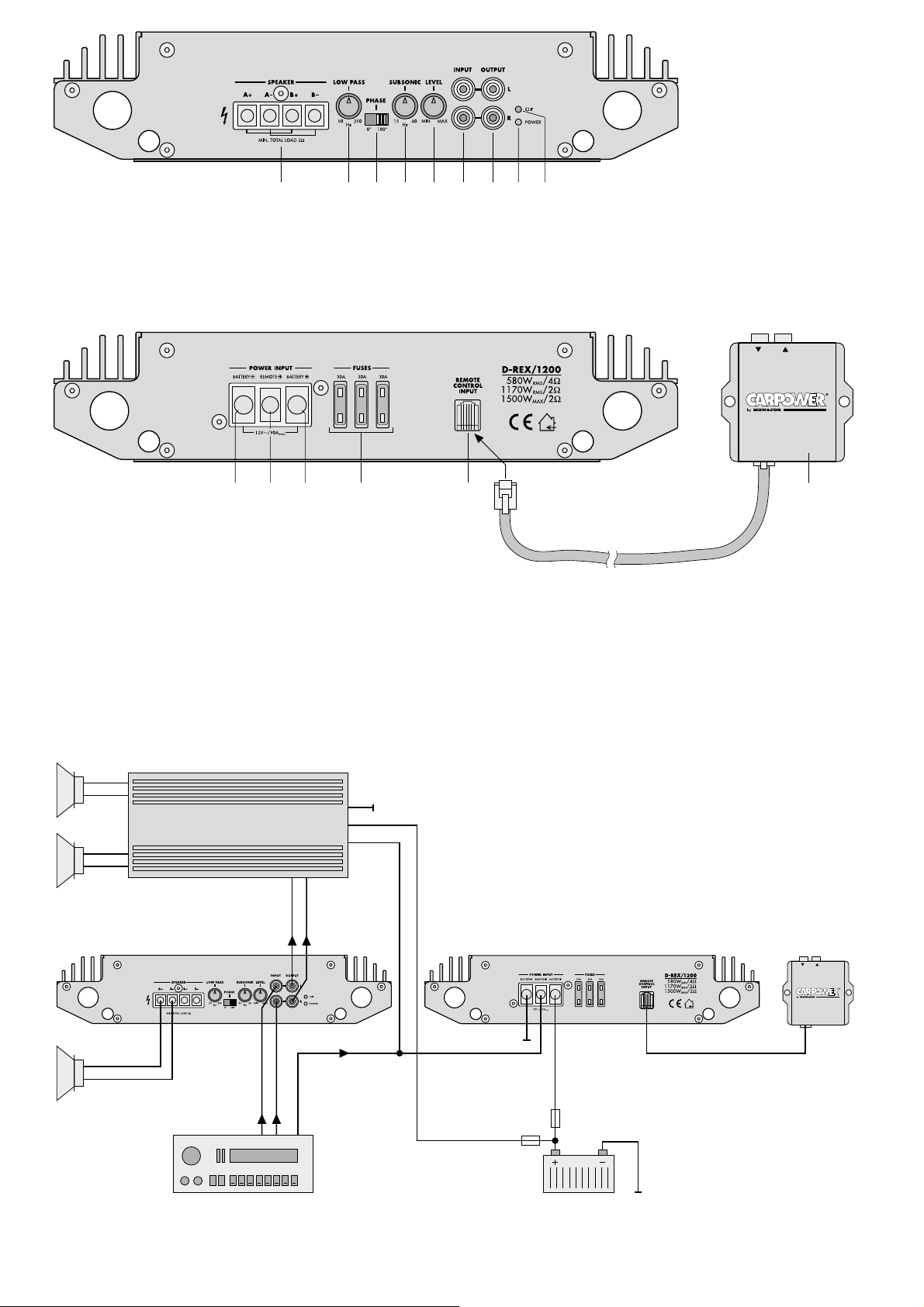
1) Réglez la fréquence de coupure avec le poten-
tiomètre LOW PASS (2) – plus la fréquence limite
supérieure est faible, plus la localisation acous-
tique d’un subwoofer est difficile. Plus la fré-
quence limite est grande, plus les graves sont
puissants. Reportez-vous aux caractéristiques
techniques des haut-parleurs utilisés.
2) Réglez la fréquence de coupure inférieure avec
le potentiomètre SUBSONIC (4). Le subwoofer
est protégé des fréquences trop basses par le fil-
tre infrason.
3) Mettez le potentiomètre LEVEL (5) au minimum
en le tournant dans le sens inverse des aiguilles
d’une montre.
4) Allumez l’ensemble de l’installation HiFi. La LED
verte POWER (8) brille. Quelques secondes plus
tard, le signal de sortie est disponible au branche-
ment SPEAKER (temporisation d’allumage).
5) Réglez la source, p. ex. l’autoradio, sur le volume
maximal non distordant (p.ex. 3/4environ du
maximum).
Truc: Pour maintenir les interférences par le
système électrique de la voiture au niveau
le plus bas, le niveau de sortie de la
source devrait être de 1,5V au moins.
6) Adaptez avec le réglage LEVEL le volume du sub-
woofer au volume des haut-parleurs principaux. En
cas de surcharge sur l’entrée, la LED rouge CLIP
(9) brille; dans ce cas, tournez le potentiomètre
LEVEL dans l’autre sens et adaptez le volume des
haut-parleurs principaux en le réduisant.
7) Lorsque vous placez les haut-parleurs, la phase
entre les ondes sonores du subwoofer et celles
des haut-parleurs principaux peut être différente
de manière que certaines fréquences sont atté-
nuées. Pour compenser cela, utilisez le commu-
tateur PHASE (3) alternativement et déterminez
la meilleure reproduction des graves sur le lieu
d’écoute. Avec le réglage LEVEL, réduisez
ensuite proportionnellement la reproduction des
graves, si nécessaire.
8) Vous pouvez corriger avec la télécommande par
câble (15) le volume du subwoofer selon le mor-
ceau de musique et la perception personnelle
depuis le siège du conducteur.
8 Problèmes et solutions
Si lors de l’allumage de l’installation HiFi, aucun son
n’est audible, la LED verte (8), témoin de fonction-
nement, peut vous aider à localiser le problème.
8.1 La LED POWER ne brille pas
1) Vérifiez les fusibles (13) sur l’amplificateur (30A
chacun) et le fusible supplémentaire de la batte-
rie de la voiture (100A). Remplacez tout fusible
défectueux. N’utilisez que des fusibles avec les
valeurs indiquées, en aucun cas de valeur
supérieure. L’amplificateur peut être endom-
magé, dans ce cas, la garantie devient caduque.
2) Contrôlez le cordon d’alimentation 12V et le
câble masse; vérifiez les connexions et la solidité
du câble.
3) Mesurez si la tension +12V est bien présente à la
borne REMOTE+ (11). Si ce n’est pas le cas, reti-
rez le câble de la borne REMOTE+ et court-cir-
cuitez avec la borne BATTERY+ (12) courte-
ment; si l’amplificateur s’allume, le problème
réside dans l’absence de tension d’alimentation:
vérifiez la sortie 12V de l’autoradio (ou de l’inter-
rupteur séparé ou de la clé) et le cordon corre-
spondant de liaison à l’amplificateur.
8.2 La LED POWER brille
1) Vérifiez le câble de liaison entre l’amplificateur et
la source. Les fiches sont-elles bien insérées? Le
câble est-il interrompu?
2) Vérifiez la source. La source est-elle allumée?
Est la sortie correcte utilisées? La source est-elle
défectueuse?
3) Vérifiez si le câble haut-parleur ne présente pas
de court-cirucit et de défaut.
4) Vérifiez le haut-parleur relié.
5) L’amplificateur est doté d’un circuit de protection
contre les surchauffes et courts-circuits sur la
sortie haut-parleur. En cas de surchauffe, l’ampli-
ficateur se rallume automatiquement une fois
correctement refroidi. En cas de court-circuit sur
la sortie haut-parleur, et une fois les problèmes
résolus, l’amplificateur doit être séparé de la ten-
sion d’alimentation pour réinitialiser le circuit de
protection (p.ex., retirez le fusible supplémen-
taire courtement).
9 Caractéristiques techniques
Puissance de sortie maximale
HP 2Ω: . . . . . . . . . . . 1500W
Puissance de sortie RMS
HP 2Ω: . . . . . . . . . . . 1170W
HP 4Ω: . . . . . . . . . . . 580W
Bande passante: . . . . . . 5–250Hz
Entrée Ligne: . . . . . . . . . réglable de 0,3 à 4V
Sortie Ligne: . . . . . . . . . signal d’entrée inséré
Fréquence de coupure: . 50–250Hz, 18 dB/oct.
Filtre subsonique: . . . . . 15–40Hz, 18dB/oct.
Rapport signal/bruit: . . . > 82dB
Taux de distorsion: . . . . < 0,1%
Impédance d’entrée: . . . 10kΩ
Impédance HP
autorisée en sortie: . . . . 2Ωminimum
Alimentation: . . . . . . . . . 11–15V , 100A max.
Température
d’utilisation: . . . . . . . . . . 0–40°C
Dimensions: . . . . . . . . . 300 x 62 x 385mm
bassi. Rispettare i dati tecnici degli altoparlanti
impiegati.
2) Impostare la frequenza limite inferiore con il
regolatore SUBSONIC (4). In questo modo, con il
filtro per infrasuoni, il subwoofer è protetto dalle
frequenze troppo basse.
3) Girare il regolatore LEVEL (5) in senso antiorario
sul minimo.
4) Accendere tutto l’impianto HiFi; la spia verde
POWER (8) rimane accesa. Dopo alcuni secondi il
segnale d’uscita è presente ai contatti SPEAKER
(ritardo d’inserimento).
5) Regolare la sorgente, p.es. l’autoradio, sul volu-
me massimo senza che vi siano delle distorsioni
(generalmente a 3/4del massimo).
Un consiglio: Per evitare il più possibile le
interferenze da parte del sistema
elettronico della macchina, il
livello d’uscita della sorgente
dovrebbe essere non inferiore a
1,5V.
6) Con il regolatore LEVEL adattare il volume del
subwoofer a quello degli altoparlanti principali.
Se l’ingresso è sovrapilotato, si accende la spia
rossa CLIP (9). Allora abbassare il regolatore
LEVELe adattare il volume degli altoparlanti prin-
cipali.
7) Il posizionamento degli altoparlanti può provo-
care fasi differenti fra le onde sonore del subwo-
ofer e quelle degli altoparlanti principali, il ché
porta all’attenuazione di determinate frequenze.
Per compensare questa circostanza spostare il
commutatore PHASE (3) alternativamente fino a
trovare la riproduzione migliore dei bassi. Suc-
cessivamente può essere opportuno ridurre leg-
germente i bassi con il regolatore LEVEL.
8) Con il telecomando via cavo (15) è possibile cor-
reggere il volume dal posto di guida secondo i
gusti personali.
8 Eliminazione di difetti
Se dopo l’accensione dell’impianto audio non si
sente niente, si può localizzare il difetto osservando
il LED verde POWER (8).
8.1 Il LED non si accende
1) Controllare i fusibili (13) sul booster (30A cad.) e
quello vicino alla batteria dell’auto (100A). Sosti-
tuire i fusibili difettosi. Usare solo fusibili con i
valori indicati. Non inserire in nessun caso un
valore maggiore. Il booster potrebbe subire dei
danni e la garanzia non sarebbe più valida.
2) Controllare il cavo di alimentazione 12V nonché
il cavo di massa. I collegamenti devono essere
corretti e non ci deve essere nessun’interruzione.
3) Verificare se al contatto REMOTE+ (11) è pre-
sente una tensione di +12V. In caso negativo,
staccare il cavo dal contatto REMOTE+ e corto-
circuitarlo brevemente con il contatto BATTERY+
(12). Se il booster si accende ora, significa che
manca la tensione di comando. Controllare l’u-
scita 12V dell’autoradio (oppure l’interruttore
separato o l’accensione della macchina) nonché
il cavo di collegamento verso il booster.
8.2 Il LED è acceso
1) Controllare i cavi di collegamento dalla sorgente
fino al booster. I connettori sono inseriti bene? È
interrotto il collegamento?
2) Controllare la sorgente. È accesa? Le uscite
sono quelle giuste? È difettosa la sorgente?
3) Controllare se ci sono interruzioni nei cavi degli
altoparlanti.
4) Controllare l’altoparlante collegato.
5) Il booster è equipaggiato con un circuito di prote-
zione contro i cortocircuiti e contro il surriscalda-
mento all’uscita altoparlanti. In caso di surris-
caldamento, dopo essersi raffreddato, il booster
si accende di nuovo automaticamente. Nel caso
di un cortocircuito all’uscita altoparlanti, dopo
l’eliminazione del difetto occorre separare il boo-
ster dall’alimentazione (staccare brevemente il
fusibile vicino alla batteria), per risettare il circuito
di protezione.
9 Dati tecnici
Potenza d’uscita max.
con altoparlante 2Ω: . 1500W
Potenza efficace
con altoparlante 2Ω: . 1170W
con altoparlante 4Ω: . 580W
Banda passante: . . . . . . 5–250Hz
Ingresso Line: . . . . . . . . regolabile da 0,3 a 4V
Uscita Line: . . . . . . . . . . segnale d’ingresso
passante
Frequenza di taglio: . . . 50–250Hz; 18dB/oct.
Filtro subsonic: . . . . . . . 15–40Hz; 18dB/oct.
Rapporto S/R: . . . . . . . . > 82dB
Fattore di distorsione: . . < 0,1%
Impedenza d’ingresso: . 10kΩ
Impedenza d’uscita am-
messa per altoparlanti: . 2Ωmin.
Alimentazione: . . . . . . . 11–15V , 100A
Temperatura d’impiego: 0–40°C
Dimensioni: . . . . . . . . . . 300x62x385mm
Peso: . . . . . . . . . . . . . . . 5,5kg
Dati forniti dal costruttore.
Con riserva di modifiche tecniche.
9
I
F
B
CH

D-REX/1200
Lees aandachtig de onderstaande veiligheidsvoor-
schriften, alvorens de apparatuur in gebruik te
nemen. Mocht u bijkomende informatie over de
bediening van de apparatuur nodig hebben, lees
dan de Duitse, Engelse, Franse, of Italiaanse tekst
van deze handleiding.
1 Veiligheidsvoorschriften
Het toestel is in overeenstemming met de EU-Richt-
lijn 89/336/EEG voor elektromagnetische compati-
biliteit.
●De aansluiting van de eindversterker van de auto-
installatie op de autobatterij dient zorgvuldig te
gebeuren. Bij kortsluiting kunnen gevaarlijk hoge
stromen ontstaan. Maak daarom voor de aansluit-
ing van de versterker de negatieve klem van de
autobatterij in ieder geval los.
●De eindversterker moet vast en deskundig op een
mechanisch stabiele plaats in de auto gemon-
teerd worden, zodat hij niet kan loskomen en op
die manier een gevaarlijk projectiel gaat vormen.
●Tijdens het gebruik kan de eindversterker zeer
warm worden. Plaats daarom geen warmtegevoe-
lige voorwerpen in de buurt, en raak de eindver-
sterker tijdens het gebruik niet aan.
●Gebruik voor de reiniging uitsluitend een droge,
zachte doek. Gebruik in geen geval chemicaliën
of water.
●In geval van ongeoorloofd of verkeerd gebruik,
foutieve bediening, verkeerde aansluiting of her-
stelling door een niet-gekwalificeerd persoon ver-
valt de garantie bij eventuele schade.
●Wanneer het toestel definitief uit bedrijf genomen
wordt, bezorg het dan voor verwerking aan een
plaatselijk recyclagebedrijf.
2 Opgelet bij hoge geluidsvolumes
●Stel het volume nooit te hoog in. Uitzonderlijk
hoge volumes kunnen het gehoor beschadigen.
●Het gehoor raakt aangepast aan hoge volumes
die na een tijdje niet meer zo hoog lijken. Draai het
volume daarom niet verder open, zelfs nadat u
eraan gewend bent.
●Zorg ervoor dat het geluidsvolume van de hifi-
installatie in de auto niet te hoog staat, waardoor
geluidssignalen, bijvoorbeeld die van een ambu-
lance, niet meer hoorbaar zouden zijn.
●Bij uitgeschakelde motor kan het audiosysteem
niet lang met een hoog geluidsvolume gebruikt
worden. De autobatterij raakt snel leeg en de kans
bestaat dat er te weinig energie is om de auto te
starten.
3 Montage
Hou bij de keuze van de montageplaats in elk geval
rekening met de volgende punten:
●De voedingsspanningskabel (12V) van de batterij
naar de eindversterker van de auto-installatie
moet zo kort mogelijk zijn. Het is voordeliger om
langere luidsprekerkabels te gebruiken en een
kortere voedingsspanningskabel.
●Zorg er ook voor dat de massakabel van de eind-
versterker naar het koetswerk zo kort mogelijk is.
●Zorg voor voldoende ventilatie om de hitte die in
de eindversterker ontstaat, af te voeren.
●Door de krachten die tijdens het remmen optre-
den, moet de eindversterker op een mechanisch
stabiele plaats vastgeschroefd worden.
●De zekeringen en de regelaar moeten makkelijk
toegankelijk zijn.
Gebruik voor de montage de vier openingen van de
behuizing. Monteer de booster met behulp van vier
schroeven op een geschikte plaats.
4 Aansluitingen
●De eindversterker mag uitsluitend door gekwalifi-
ceerd personeel op het elektrische circuit van de
auto aangesloten worden.
●Om schade door eventuele kortsluiting tijdens de
installatie te vermijden, koppelt u best de nega-
tieve klem los van de autobatterij, alvorens de
aansluiting uit te voeren.
●Breng de nodige kabels zo aan, dat de isolatie
ervan niet beschadigd kan worden.
De volledige aansluiting vindt u terug in figuur 4 op
pagina 3.
D-REX/1200
Por favor, antes del uso del aparato observar en
todo caso las instrucciones de seguridad siguientes.
Si informaciones adicionales son necesarias para la
operación del aparato, estas se encuentran en el
texto alemán, inglés, francés o italiano de estas
instrucciones.
1 Consejos de utilización
Este amplificador cumple la norma europea
89/336/CEE relativa a la compatibilidad electro-
magnética.
●Cuando se conecta el amplificador a la batería del
coche se debe ser muy prudente; en caso de
corto-circuito, circulan corrientes muy elevadas y
por lo tanto peligrosas. Es por esto que antes de
efectuar cualquier conexión, debe desconectarse
el borne negativo de la batería.
●El aparato debe estar fijado solidamente en un
lugar mecánicamente estable para evitar que no
se deslice y no se transforme en un proyectil peli-
groso.
●Durante su funcionamiento, puede calentarse
mucho; le recomendamos no poner objetos sensi-
bles al calor cerca del amplificador y de no tocarlo
durante su funcionamiento.
●Para limpiarlo, sólo utilizar un paño seco y suave,
en ningún caso productos químicos o agua.
●Declinamos cualquier responsabilidad en caso de
desperfectos si el aparato ha sido utilizado para
otra finalidad para la que sa ha construido, si se
ha utilizado o cableado de manera incorrecta o si
no ha sido reparado de manera experta.
●Cuando el aparato se retira definitivamente del
circuito de distribución, debe depositarse en una
fábrica de reciclaje adaptada.
2 Atención en caso de volúmenes
elevados
●No regular el volumen demasiado fuerte. Los
volúmenes muy elevados pueden dañar el oído.
●El oído humano se habitua a los volúmenes muy
elevados y, después de cierto tiempo, no los per-
cibe de la misma manera. Es por eso que le reco-
mendamos no aumentar el volumen una vez que
se ha habituado.
●No regular nunca el volumen del sistema audio
demasiado fuerte: se deben poder oír siempre los
ruidos exteriores, por ejemplo, una ambulancia.
●Cuando el contacto del vehículo está cortado, no
dejar funcionar el amplificador mucho tiempo a
pleno regimen, la batería del vehículo se des-
carga rápidamente, pudiendo de esta manera
agotarla y no arrancar el mismo.
3 Montaje
Cuando escoger el lugar de instalación del aparato,
respetar en todo caso los puntos siguientes:
●El cable de alimentación 12V que conecta la
batería y el amplificador debería ser lo más corto
posible; es preferible utilizar cables de altavoz
más largos y un cable de alimentación más corto.
●El cable de masa que conecta el amplificador al
chasis del vehículo debería ser lo más corto posi-
ble.
●Para permitir una evacuación correcta del calor
generado por el amplificador, vigilar en asegu-
rarse que existe una buena ventilación.
●A causa de las fuerzas durante el frenaje, puede
transformarse en proyectil peligroso, vigilar en
fijarlo correctamente en un sitio mecánicamente
estable.
●Los fusibles y componentes deben tener fácil
acceso.
Montarlo en el lugar requerido fijando los 4 tornillos
entregados dentro los 4 agujeros de fijación previs-
tos en la caja.
4 Conexiones
●Las conexiones del amplificador al sistema eléc-
trico deben efectuarse por un técnico debida-
mente especializado.
●Para evitar cualquier corto-circuito a la hora de
instalarlo, y así cualquier posible daño, desatornil-
lar el borne negativo de la batería del automóvil.
●Colocar los cables de tal manera que su aisla-
miento no sea dañado.
Encontrará en el esquema 4, página 3, el conjunto
de conexiones.
10
NL
B
E

D-REX/1200
Læs nedenstående sikkerhedsoplysninger opmærk-
somt igennem før ibrugtagning af enheden. Bortset
fra sikkerhedsoplysningerne henvises til den engel-
ske, tyske, franske eller italienske tekst.
1 Vigtige sikkerhedsoplysninger
Enheden overholder EU-direktivet vedrørende elek-
tromagnetisk kompatibilitet 89/336/EØF.
●Vær særligt forsigtig, når HiFi-forstærkeren skal
tilsluttes bilens batteri. Der kan i tilfælde af korts-
lutning opstå store strømme, som kan være far-
lige. Det er derfor absolut nødvendigt, at forbin-
delsen til den negative pol på bilens batteri
afbrydes før tilslutning af enheden.
●For at sikre, at forstærkeren ikke ryster løs og ved
for eksempel hård opbremsning bliver til et farligt
projektil, skal den fastspændes sikkert og solidt i
bilen på et mekanisk stabilt sted.
●Forstærkeren kan blive meget varm under drift.
Undlad derfor at placere varmefølsomme objekter
i nærheden af den eller at røre ved den under drift.
●Til rengøring må der kun benyttes en tør, blød
klud; der må under ingen omstændigheder benyt-
tes kemikalier eller vand.
●Hvis forstærkeren benyttes til andre formål, end
den oprindeligt er beregnet til, hvis den betjenes
forkert, hvis den ikke er korrekt tilsluttet, eller hvis
den ikke repareres af autoriseret personel, omfat-
tes eventuelle skader ikke af garantien.
●Hvis enheden skal tages ud af drift for bestandigt,
skal den bringes til en lokal genbrugsstation for
bortskaffelse.
2 Forsigtighed ved høje volumen
●Der må aldrig skrues for højt op for volumen.
Meget kraftig lyd kan beskadige hørelsen.
●Menneskets hørelse vænner sig til kraftig lyd, så
lyden efter et stykke tid ikke opleves så kraftig.
Undlad derfor at skrue mere op for lyden efter til-
vænning til den indstillede volumen.
●Volumen for bilens HiFi-system må aldrig justeres
til et så højt niveau, at signallyde såsom sirenen
fra en ambulance ikke kan høres.
●Lydsystemet bør ikke indstilles til høj volumen i
længere tid, når bilens motor er slukket. Bilens
batteri aflades hurtigt og kan derfor blive ude af
stand til at levere tilstrækkelig strøm til start af
motoren.
3 Montering
Vær altid opmærksom på følgende punkter ved valg
af monteringssted:
●12V strømforsyningskablet fra batteriet til HiFi-
forstærkeren bør være så kort som muligt. Det er
bedre at benytte lange højttalerkabler og et kort
strømforsyningskabel.
●Kablet for tilslutning af stel, som forbinder forstær-
keren til bilens stel, bør ligeledes være så kort
som muligt.
●Sørg for at sikre tilstrækkelig ventilation for at
kunne bortlede den varme, der dannes i forstær-
keren.
●Forstærkeren skal monteres på et mekanisk sta-
bilt sted for at kunne modstå den energi, der dan-
nes i forbindelse med opbremsning.
●Der skal være fri adgang til sikringer og betje-
ningselementer.
Brug de fire udborede huller i kabinettet til monte-
ring. Fastgør boosteren på et passende sted med
fire skruer.
4 Tilslutninger
●Tilslutning af HiFi-forstærkeren til bilens elektriske
system må kun foretages af autoriseret personel.
●Det er absolut nødvendigt at afbryde forbindelsen
til den negative pol på bilens batteri før tilslutning
for at undgå beskadigelse ved en eventuel korts-
lutning.
●Placér de nødvendige kabler på en sådan måde,
at deres isolering ikke kan blive beskadiget.
Den komplette tilslutning er vist på figur 4 side 3.
D-REX/1200
Innan enheten tas i bruk, läs först igenom säkerhets-
föreskrifterna. Om ytterligare information önskas,
läs igenom den tyska, engelska, franska eller den
italienska texten som medföljer.
1 Säkerhetsföreskrifter
Enheten uppfyller EG-direktiv 89/336/EWG av-
seende elektromagnetiska störfält.
●Vid anslutning i bil, var särskilt försiktig så att inte
kortslutning uppstår. Vid kortslutning rusar mycket
stora strömmar i kablaget vilket kan ge upphov till
kabelbrand. Lossa alltid minuspolen från batteriet
innan några anslutningar görs.
●Slutsteget skall monteras på ett mekaniskt stabilt
ställe. Skruva noga fast slutsteget så att det inte
kan lossna och orsaka skador.
●Vid användning blir slutsteget ibland mycket
varmt. Se till att luften kan cirkulera fritt runt slut-
steget. Placera inte känsliga föremål i direkt när-
het av slutsteget. Rör inte heller slutsteget då det
är påslaget utan låt det kallna några minuter innan
det berörs.
●Rengör endast med en ren och torr trasa, använd
inte vätskor i någon form då dessa kan rinna in
och orsaka kortslutning.
●Om slutsteget används för andra ändamål än
avsett, om den används på fel sätt och inte blir
reparerad av auktoriserad personal, upphör alla
serviceanspråk att gälla.
●Om slutsteget skall kasseras bör det lämnas till
återvinning.
2 Varning vid höga volymer
●Ställ aldrig volymen för högt. Höga volymen med
starka transienter kan ge permanenta hörselska-
dor.
●Örat vänjer sig vid höga volymer efter hand. Öka
inte volymen ytterligare efter att örat “ställt in sig”
på den höga volymen.
●Under färd bör volymen inte bli högre än att trafik-
ljud som ex.vis. signalhorn från utryckningsfordon
fortfarande kan höras.
●Med motorn avstängd bör inte audiosystemet
användas under längre tid. Bilbatteriet urladdas
fort och kanske inte kan tillföra tillräcklig energi för
att bilen ska starta.
3 Montering
Vid placering av slutsteget är det viktigt att beakta
följande.
●12V anslutningen till slutsteget skall vara så kort
som möjligt. Det är bättre med långa högtalar-
kablar än långa elkablar.
●Jordkabel skall anslutas chassit så nära slutsteget
som möjligt.
●För att kyla av slutsteget skall detta monteras luf-
tigt så att ventilationen inte försämras.
●Vid kraftiga inbromsningar kan ett slutsteg bli en
farlig projektil, montera därför stabilt med rätt antal
skruvar direkt i plåt.
●Säkringarna och element som används måste
vara tillgängliga.
Använd de 4 förborrade hålen på höljet vid monte-
ring. Montera försiktigt fast slutsteget med 4 skruvar
på lämpligt ställe.
4 Anslutningar
●Anslutning av slutsteget till bilens elsystem skall
göras av person med elvana.
●För att undvika elskador och kabelbrand vid mon-
tering, lossa först minuspolen på bilbatteriet.
●Lägg alla kablar så att de inte kan skadas.
Installationsskiss visas i fig. 4 på sid. 3.
11
DK
S

D-REX/1200
Ole hyvä ja huomioi aina seuraavat turvallisuutta
koskevat ohjeet ennen laitteen käyttöön ottoa. Katso
käyttöön liittyviä ohjeita Saksan, Englannin, Rans-
kan tai Italian kielisistä ohjeista, jos tarvitset lisää
tietoa laitteen käytöstä.
1 Turvallisuudesta
Laite vastaa direktiivin 89/336/EEC vaatimuksia
sähkömagneettisesta yhteensopivuudesta.
●Ole erityisen varovainen kytkiessäsi virtaa auto
HiFi vahvistimeen. Oikosulku voi aiheuttaa vaaral-
lisen korkean jännitteen. Sen vuoksi on ehdotto-
man välttämätöntä irrottaa akun maadoitusjohto
(
-
) ennen virran kytkemistä.
●Vahvistin tulee asentaa autossa turvalliseen paik-
kaan ammattitaidolla, ettei se pääse irtoamaan ja
aiheuta sinkoutuessaan vaaraa.
●Käytön aikana vahvistin voi kuumeta paljonkin.
Sen vuoksi älä sijoita mitään herkästi kuumenevia
esineitä lähelle vahvistinta, äläkä kosketa sitä.
●Puhdistukseen käytä vain kuivaa, pehmeää kan-
gasta ilman kemikaaleja tai vettä.
●Jos vahvistinta käytetään muuhun kuin alkuperäi-
seen tarkoitukseen, jos sitä ei ole käytetty tai
asennettu oikein tai ei ole korjattu valtuutetussa
huollossa, valmistaja tai maahantuoja eivät
vastaa mahdollisista vahingoista.
●Jos laite poistetaan lopullisesti käytöstä, se tulee
antaa jätteenkäsittelylaitoksen hävitettäväksi.
2 Varoitus suuresta äänenvoimakkuu-
desta
●Älä koskaan aseta äänenvoimakkuutta erityisen
voimakkaaksi, sillä se saattaa vahingoittaa kuu-
loa.
●Ihmiskorva tottuu kovaan äänenvoimakkuuteen,
joka jonkun ajan kuluttua ei enää tunnu niin voim-
akkaalta. Sen tähden älä lisää äänenvoimak-
kuutta enää siitä, mitä kerran olet alkanut käyttää.
●Ajon aikana äänen voimakkuus ei saa estää
kuulemasta esim. ambulanssin hälytysääntä.
●Auton moottorin ollessa pois käynnistä, älä kuun-
tele äänentoistolaitteistoa suurella voimakkuu-
della kovin pitkää aikaa, koska akku tällöin pur-
kautuu nopeasti, eikä siitä mahdollisesti riitä
energiaa auton käynnistämiseksi.
3 Kiinnitys
Kiinnityspaikkaa valittaessa on seuraavat seikat
joka tapauksessa huomioitava:
●Akulta tulevan 12V virtajohdon tulisi olla niin lyhyt
kuin mahdollista. Pidemmät kaiutinkaapelit ja
lyhyempi virtakaapeli tulevat edullisimmaksi.
●Käytä mahdollisimman lyhyttä maadoituskaapelia
vahvistimen ja auton rungon välillä.
●Varmista riittävä tuuletus vahvistimen aiheutta-
man lämmön takia.
●Kiinnitä vahvistin lujasti kestävälle alustalle, ettei
vahvistin irtoa äkkijarrutuksessa.
●Sulake ja hallintalaitteet asennetaan siten, että ne
ovat helposti saatavilla.
Käytä asennuksessa kuusiokoloruuveja. Kiinnitä
vahvistin tukevasti neljällä ruuvilla.
4 Liitännät
●HiFi vahvistin täytyy aina asentaa auton sähköjär-
jestelmään valtuutetussa huollossa.
●Mahdollisen oikosulun aiheuttaman vahingon vält-
tämiseksi on aina asennuksen ajaksi irrotettava
maadoituskaapeli akun miinusnavasta.
●Aseta välttämättömät kaapelit niin, etteivät niiden
eristeet vaurioidu.
Täydelliset liitännät on esitetty kuvassa 4 sivulla 3.
12
FIN

Copyright
©
by MONACOR
®
International GmbH & Co. KG, Bremen, Germany. All right re erved.
www.monacor.com 12.00.01
This manual suits for next models
1
Table of contents
Other Monacor Extender manuals
Popular Extender manuals by other brands

HDanywhere
HDanywhere XTND4K100TPC manual

Extron electronics
Extron electronics EDID 101H 4K Setup guide

TP-Link
TP-Link TL-WPA7617 user guide

Shinybow USA
Shinybow USA CAT-5 YUV Series instruction manual

Rose electronics
Rose electronics CrystalView CRK-1DTXT-HD5 Installation and operation manual

Apantac
Apantac HDBT-1-Es-POE-UHD user manual