Monacor CARPOWER HPB-502 User manual

HPB-502
Best.-Nr. 14.2040
HPB-1002
Best.-Nr. 14.2060
Montageanleitung • Mounting instructions
Notice d’utilisation • Istruzioni per il montaggio
Veiligheidsvoorschriften • Consejos de seguridad
Sikkerhedsoplysninger • S kerhetsföreskrifter
Turvallisuudesta
2kanalige Car-HiFi-Endstufe
2-Channel Car HiFi Booster
Amplificateur HiFi Em arquée,
2 Canaux
Booster HiFi a 2 Canali per Auto

2
Voordat u inschakelt ...
Wij wensen u veel plezier met uw nieuw toe-
stel van CARPOWER. Lees de veiligheids-
voorschriften, alvorens het toestel in gebruik
te nemen. Door de veiligheidsvoorschriften
op te volgen zal een slechte werking verme-
den worden, en zal een eventueel letsel aan
uzelf en schade aan uw toestel tengevolge
van onzorgvuldig gebruik worden voorkomen.
U vindt de veiligheidsvoorschriften op pagina
20.
NL
B
Vor der Montage ...
Wir wünschen Ihnen viel Spaß mit dem neuen
Gerät von CARPOWER. Diese Anleitung soll
Ihnen eine schnelle und einfache Montage
ermöglichen. Sie finden dazu hier alle nötigen
Informationen. Durch die Beachtung der An-
leitung werden außerdem eventuelle Schä-
den am Gerät durch unsachgemäße Montage
vermieden.
Der deutsche Text beginnt auf der Seite 4.
D
A
CH
Prior to Mounting ...
We wish you much pleasure with the new unit
by CARPOWER. With these operating in-
structions a quick and easy mounting will be
possible. You will find all necessary informa-
tion here. By following these instructions pos-
sible damage to the unit due to improper mo-
unting will be prevented.
The English text starts on page 8.
GB
Avant toute installation ...
Nous vous souhaitons beaucoup de plaisir à
utiliser cet appareil CARPOWER. Cette no-
tice a pour objectif de faciliter le montage.
Vous y trouverez toutes les informations né-
cessaires. En outre, en respectant les con-
seils donnés, vous éviterez tout mauvais
montage et donc d’endommager l’appareil.
La version française commence page 12.
F
B
CH
Prima del montaggio ...
Vi auguriamo buon divertimento con il vostro
nuovo apparecchio CARPOWER. Le istru-
zioni che contengono tutte le informazioni ne-
cessarie Vi permettono un montaggio rapido
e semplice. Rispettando quanto spiegato
nelle istruzioni evitate eventuali danni all’ap-
parecchio in seguito ad un montaggio non a
regola d’arte.
Il testo italiano inizia a pagina 16.
I
Antes de cualquier instalación ...
Tenemos de agradecerle el haber adquirido
un equipo de CARPOWER y le deseamos un
agrable uso. Por favor lee las instrucciones
de seguridad antes del uso. La observación
de las instrucciones de seguridad evita ope-
raciones erróneas y protege Vd. y vuestro
aparato contra todo daño posible por cual-
quier uso inadecuado.
Las instrucciones de seguridad se encuen-
tran en la página 21.
Inden De tænder for apparatet ...
Vi ønsker Dem god fornøjelse med Deres nye
CARPOWER apparat. Læs oplysningerne for
en sikker brug af apparatet før ibrugtagning.
Følg sikkerhedsoplysningerne for at undgå
forkert betjening og for at beskytte Dem og
Deres apparat mod skade på grund af forkert
brug.
Sikkerhedsoplysningerne finder De på side 22.
DK
E
SFörskrift
Vi önskar dig mycket nöje med din nya enhet
från CARPOWER. Läs gärna säkerhetsin-
struktionerna innan du använder enheten.
Genom att följa säkerhetsinstruktionerna kan
många problem undvikas, vilket annars kan
skada enheten.
Du finner säkerhetsinstruktionerna på sidan
23.
Ennen virran kytkemistä…
Toivomme, että uusi CARPOWER-laitteesi
tuo sinulle paljon iloa ja hyötyä. Ole hyvä ja
lue käyttöohjeet ennen laitteen käyttöönottoa.
Luettuasi käyttöohjeet voit käyttää laitetta tur-
vallisesti ja vältyt laitteen väärinkäytöltä.
Käyttöohjeet löydät sivulta 24.
FIN

bridge mode
fuse
+
12v rem ground
speakers
RL
power
protection
R
L
line in
FLAT
HIGHPASS
LOWPASS
selecter level lowpass highpass
900
530 1.5kHz
65 4.5kHz
85
2.3kHz
250
40 460
50
370
8v 100mv
Radio
Speaker L (R)
min. 4Ω
Battery
Fuse
15A – HPB-502
25A – HPB-1002
Chassis
Chassis
On = 12VL (R)
bridge mode
fuse
+
12v rem ground
speakers
RL
power
protection
R
L
line in
FLAT
HIGHPASS
LOWPASS
selecter level lowpass highpass
900
530 1.5kHz
65 4.5kHz
85
2.3k
250
40 460
50
370
8v 100mv
bass boost
0 +18dB
3
➀
➁
123 4 5 6 7 8
9101112 13
bridge mode
fuse
+
12v rem ground
speakers
RL
power
protection
R
L
line in
FLAT
HIGHPASS
LOWPASS
selecter level lowpass highpass
900
530 1.5kHz
65 4.5kHz
85
2.3kHz
250
40 460
50
370
8v 100mv
Radio
Speaker R
min. 2ΩSpeaker L
min. 2Ω
Battery
Fuse
15A – HPB-502
25A – HPB-1002
Chassis
Chassis
On = 12VRL
Brückenbetrieb • Bridge operation
Mode bridgé • Funzionamete a ponte ➃
2-Kanalbetrieb • 2 channel operation
Mode 2 canaux • Funzionamento a 2 canali ➂

Bitte klappen Sie die Seite 3 heraus. Sie sehen
dann immer die beschriebenen Bedienelemente
und Anschlüsse.
Inhalt
1 Übersicht der Bedienelemente und An-
schlüsse . . . . . . . . . . . . . . . . . . . . . . . . . . . . . 4
2 Sicherheitshinweise . . . . . . . . . . . . . . . . . . . 4
3 Vorsicht bei hohen Lautstärken . . . . . . . . . . 5
4 Einsatzmöglichkeiten . . . . . . . . . . . . . . . . . . 5
5 Montage . . . . . . . . . . . . . . . . . . . . . . . . . . . . . 5
6 Endstufe anschließen . . . . . . . . . . . . . . . . . . 5
6.1 Stromversorgung . . . . . . . . . . . . . . . . . . . . . . . 5
6.1.1 Anschluß „+12v“ . . . . . . . . . . . . . . . . . . . . . . 5
6.1.2 Anschluß „ground“ . . . . . . . . . . . . . . . . . . . . . 5
6.1.3 Anschluß „rem“ . . . . . . . . . . . . . . . . . . . . . . . 5
6.2 Eingänge . . . . . . . . . . . . . . . . . . . . . . . . . . . . . 5
6.3 Lautsprecher . . . . . . . . . . . . . . . . . . . . . . . . . . 5
6.3.1 2-Kanalbetrieb . . . . . . . . . . . . . . . . . . . . . . . . 6
6.3.2 Brückenbetrieb . . . . . . . . . . . . . . . . . . . . . . . 6
6.3.3 Tri-Mode . . . . . . . . . . . . . . . . . . . . . . . . . . . . 6
7 Inbetriebnahme . . . . . . . . . . . . . . . . . . . . . . . 6
7.1 Filter einschalten und Trennfrequenz
einstellen . . . . . . . . . . . . . . . . . . . . . . . . . . . . . 6
7.2 Pegel anpassen . . . . . . . . . . . . . . . . . . . . . . . . 6
8 Fehlerbeseitigung . . . . . . . . . . . . . . . . . . . . . 7
8.1 Keine LED leuchtet . . . . . . . . . . . . . . . . . . . . . 7
8.2 Grüne LED „power“ leuchtet . . . . . . . . . . . . . . 7
8.3 Rote LED „protection“ leuchtet . . . . . . . . . . . . . 7
9 Technische Daten . . . . . . . . . . . . . . . . . . . . . . 7
1 Übersicht der Bedienelemente und An-
schlüsse
1Anzeige „protection“ leuchtet bei aktivierter Schutz-
schaltung:
1. ca. 3 Sekunden lang nach dem Einschalten
(Einschaltverzögerung)
2. wenn einer der Lautsprecherausgänge (13) kurz-
geschlossen ist
3. wenn der Verstärker überhitzt ist
2Betriebsanzeige
3Schalter für die Filter
LOWPASS: Tiefpaß eingeschaltet (für Subwoofer)
HIGHPASS: Hochpaß eingeschaltet (für Mittel-
hochtöner)
FLAT: kein Filter eingeschaltet (für Breit-
bandlautsprecher)
4Trimmregler zur Eingangspegelanpassung
5Trimmregler für die Trennfrequenz des Tiefpasses
6Trimmregler für die Trennfrequenz des Hochpasses
7(nur bei HPB-1002) Regler „bass boost“ zur Baß-
anhebung
8Line-Eingänge (L/R)
9Sicherung 15A (HPB-502) bzw. 25A (HPB-1002);
eine durchgebrannte Sicherung nur durch eine
gleichen Typs ersetzen
10 Anschluß für die Versorgungsspannung +12V
11 Steuereingang „rem“ zum Einschalten der Car-
HiFi-Endstufe über eine 12-V-Spannung
12 Masseanschluß „ground“
13 Lautsprecheranschlüsse
2 Sicherheitshinweise
Das Gerät entspricht der Richtlinie 89/336/EWG für
elektromagnetische Verträglichkeit.
●Beim Anschluß der Car-HiFi-Endstufe an die Auto-
batterie ist besondere Sorgfalt geboten. Bei Kurz-
schlüssen können sehr gefährlich hohe Ströme
fließen. Schrauben Sie deshalb unbedingt vor dem
Anschluß die Minusklemme der Autobatterie ab.
●Die Endstufe muß fest und fachgerecht an einer
mechanisch stabilen Stelle imAuto montiert werden,
damit sie sich nicht löst und zu einem gefährlichen
Geschoß wird.
●Während des Betriebs kann das Gerät sehr heiß
werden. Plazieren Sie darum keine hitzeempfind-
lichen Gegenstände in der Nähe, und berühren Sie
die Endstufe nicht während des Betriebs.
●Verwenden Sie für die Reinigung nur ein trockenes,
weiches Tuch, auf keinen Fall Chemikalien oder
Wasser.
●Wird das Gerät zweckentfremdet, falsch bedient,
nicht richtig angeschlossen oder nicht fachgerecht
repariert, kann für eventuelle Schäden keine Haf-
tung übernommen werden.
●Soll das Gerät endgültig aus dem Betrieb genom-
men werden, übergeben Sie es zur Entsorgung ei-
nem örtlichen Recyclingbetrieb.
D
A
CH
4

3 Vorsicht bei hohen Lautstärken
●Stellen Sie die Lautstärke nie sehr hoch ein. Extrem
hohe Lautstärken können das Gehör schädigen.
●Das menschliche Ohr gewöhnt sich an große Laut-
stärken und empfindet sie nach einiger Zeit als nicht
mehr so hoch. Erhöhen Sie darum eine einmal ein-
gestellte hohe Lautstärke nach der Gewöhnung
nicht weiter.
●Während des Autofahrens dürfen Signaltöne, z.B.
von einem Rettungswagen, nicht durch eine zu
große Lautstärke der Car-HiFi-Anlage übertönt
werden.
4 Einsatzmöglichkeiten
Die Endstufen HPB-502 und HPB-1002 sind speziell
für Car-HiFi-Anlagen konzipiert und können zwei
Breitbandlautsprecher antreiben. Durch die integrier-
ten Frequenzweichen läßt sich mit einer zusätzlichen
Endstufe auch ein 2-Wege-Aktivsystem mit zwei Mit-
telhochtönern und zwei Baßlautsprechern bzw. einem
Subwoofer realisieren. Um eine größere Ausgangslei-
stung zu erhalten, kann die Endstufe im Brückenbe-
trieb einen Lautsprecher antreiben.
5 Montage
Bei der Auswahl des Montageplatzes unbedingt die
folgenden Punkte beachten:
●Das 12-V-Stromversorgungskabel von der Batterie
zur Car-HiFi-Endstufe sollte so kurz wie möglich
sein. Es ist günstiger, längere Lautsprecherkabel zu
verwenden und dafür ein kürzeres Stromversor-
gungskabel.
●Die Masseleitung von der Endstufe zum Fahrzeug-
chassis sollte ebenfalls so kurz wie möglich sein.
●Um die entstehende Wärme der Car-HiFi-Endstufe
ableiten zu können, muß eine ausreichende Belüf-
tung gewährleistet sein.
●Wegen der beim Bremsen auftretenden Kräfte muß
die Endstufe an einer mechanisch stabilen Stelle
angeschraubt werden.
●Die Sicherung und die Regler müssen zugänglich
sein.
Zur Montage die vier Bohrungen am Kühlkörper ver-
wenden. Die Car-HiFi-Endstufe an geeigneter Stelle
mit vier Schrauben fest montieren.
6 Endstufe anschließen
●Der Anschluß der Car-HiFi-Endstufe an das Bord-
netz darf nur durch qualifiziertes Fachpersonal er-
folgen.
●Um bei einem eventuellen Kurzschluß während der
Installation Schäden zu vermeiden, schrauben Sie
unbedingt vor dem Anschluß die Minusklemme der
Autobatterie ab.
●Verlegen Sie die erforderlichen Kabel so, daß deren
Isolierung nicht beschädigt werden kann.
Der Anschluß ist in Abb. 3 bzw. Abb. 4 dargestellt.
6.1 Stromversorgung
6.1.1 Anschluß „+12v“ (10)
Den Anschluß „+12v“ über ein Kabel mit einem Quer-
schnitt von mindestens 10mm2(z.B. CPC-100/RT
von CARPOWER) mit der Plusklemme der Autobatte-
rie verbinden. Um die neu verlegte 12-V-Leitung gegen
einen Kurzschluß abzusichern, unbedingt eine Vor-
sicherung (15A für HPB-502 bzw. 25A für HPB-1002)
in unmittelbarer Nähe der Batterie zwischensetzen
(Abb.3).
Zur Stabilisierung der Betriebsspannung für die
Endstufe und der damit verbundenen Leistungssteige-
rung sowie Klangverbesserung wird ein Power-Kon-
densator empfohlen (z.B. CPS-500 oder CPS-1000
von CARPOWER).
6.1.2 Anschluß „ground“ (12)
Den Masseanschluß „ground“ über ein Kabel mit
einem Querschnitt von mindestens 10mm2(z.B.
CPC-100/SW von CARPOWER) mit der Masse des
Autos oder direkt mit der Minusklemme derAutobatte-
rie verbinden. Zur Vermeidung von Masseschleifen
muß die Masse des Autoradios an die Stelle gelegt
werden, an der auch die Endstufe an Masse liegt.
6.1.3 Anschluß „rem“ (11)
Die Car-HiFi-Endstufe wird durch eine Steuerspannung
von +12V am Anschluß „rem“ ein- und ausgeschaltet.
DenAnschluß „rem“ mit dem 12-V-Ausgang vomAuto-
radio verbinden (Anschluß für eine Motorantenne,
eventuell mit der Motorantenne parallelschalten).
Wenn kein 12-V-Ausgang am Autoradio vorhanden
ist, muß der Anschluß „rem“ +12V über das Zünd-
schloß oder über einen separaten Schalter erhalten.
6.2 Eingänge
Die beiden Eingänge „line in“ (8) über Cinch-Kabel mit
den entsprechenden Line-Ausgängen am Autoradio
verbinden (Abb. 3). Sind amAutoradio keine Line-Aus-
gänge vorhanden, alternativ die Lautsprecheraus-
gänge des Autoradios über einen entsprechenden
Übertrager (z.B. FGA-20 von CARPOWER) mit den
Eingängen der Endstufe verbinden.
Soll die Endstufe im Brückenbetrieb einen Laut-
sprecher für den rechten oder linken Kanal antreiben,
beide Eingänge „line in“ gemeinsam über ein Y-Kabel
(z.B. CBA-25/SW von CARPOWER) mit dem Line-
Ausgang des rechten bzw. linken Kanals amAutoradio
verbinden – siehe auch Abb. 4. (Wird im Brückenbe-
trieb jedoch ein Mono-Subwoofer angetrieben, die
Eingänge, wie im Abb. 3 dargestellt, getrennt an-
schließen.)
6.3 Lautsprecher
Es können Breitbandlautsprecher, Mittelhochtöner
oder Baßlautsprecher bzw. ein Subwoofer betrieben
werden. Im 2-Kanalbetrieb kann die Endstufe die Laut-
sprecher für den linken und rechten Kanal antreiben
oder im Brückenbetrieb mit erhöhterAusgangsleistung
den Lautsprecher für einen Kanal oder einen Sub-
woofer.
Wichtig! Alle Lautsprecher müssen 2polig ange-
D
A
CH
5

schlossen werden, d.h. ohne gemeinsa-
men Masseanschluß.
Bei der Auswahl geeigneter Lautsprecher
unbedingt deren mechanische und elektri-
sche Belastbarkeit im Zusammenhang mit
der genutzten Endstufenleistung berück-
sichtigen (siehe auch technische Daten der
Endstufe Seite 7).
6.3.1 2-Kanalbetrieb
Die größte Ausgangsleistung wird beim Anschluß von
2-Ω-Lautsprechern oder einer Lautsprechergruppe mit
einer Gesamtimpedanz von 2Ωpro Kanal erreicht
(z.B. zwei 4-Ω-Lautsprecher oder vier 8-Ω-Lautspre-
cher parallelgeschaltet). Es können jedoch auch ein-
zelne 4-Ω- oder 8-Ω-Lautsprecher angeschlossen
werden, wobei sich die Ausgangsleistung verringert.
Die Lautsprecher an die Klemmen „speakers“ (13)
anschließen – siehe auch Abb. 3:
R
-
= Minuspol rechter Lautsprecher
R+ = Pluspol rechter Lautsprecher
L
-
= Minuspol linker Lautsprecher
L+ = Pluspol linker Lautsprecher
6.3.2 Brückenbetrieb
Im Brückenbetrieb darf die Impedanz des angeschlos-
senen Lautsprechers bzw. die Gesamtimpedanz einer
Lautsprechergruppe 4Ωnicht unterschreiten! Den
Lautsprecher an die Klemmen „speakers“ (13) an-
schließen, wobei die Beschriftung „bridge mode“ zu
beachten ist – siehe auch Abb. 4:
R
-
= Minuspol
R+ = bleibt frei
L
-
= bleibt frei
L+ = Pluspol
6.3.3 Tri-Mode
Im Tri-Mode werden ein Subwoofer im gebrückten
Monobetrieb und zwei Mittelhochtöner im 2-Kanalbe-
trieb angetrieben. Hierzu ist eine geeignete Tri-Mode-
Weiche erforderlich. Die Impedanz der angeschlosse-
nen Lautsprecher darf 4Ωnicht unterschreiten!
Möglich ist der Tri-Mode für beide Modelle HPB-
502 und HPB-1002. Wegen der benötigten Leistungs-
reserve wird diese Betriebsart jedoch nur für das
Modell HPB-1002 empfohlen.
Die Lautsprecher über eine geeignete Tri-Mode-Wei-
che an die Klemmen „speakers“ (13) anschließen:
Tri-Mode ➄
7 Inbetriebnahme
Vor dem ersten Einschalten das entsprechende
Filter einschalten und die Trennfrequenz grob ein-
stellen (Kap. 7.1), damit die Lautsprecher nicht
durch einen eventuellen zu großen Frequenz-
bereich überlastet werden. Auch sollte die kom-
plette Verdrahtung der Car-HiFi-Endstufe noch
einmal auf Richtigkeit überprüft werden. Erst da-
nach die Minusklemme der Autobatterie wieder
anschließen.
7.1 Filter einschalten und Trennfrequenz ein-
stellen
Je nach verwendetem Lautsprechertyp mit dem
Schalter „selecter“ (3) das benötigte Filter einschalten:
Für Breitbandlautsprecher den Schalter in die Posi-
tion FLAT stellen. Damit sind alle Filter ausgeschaltet
und die Regler „lowpass“ (5) und „highpass“ (6) ohne
Funktion. Die Endstufe gibt den ganzen Frequenzbe-
reich wieder.
Für Mittelhochtöner den Schalter in die Position
HIGHPASS stellen. Der Hochpaß ist eingeschaltet,
und die tiefen Frequenzen werden damit unterdrückt.
Die Trennfrequenz mit dem Regler „highpass“ (6)
zunächst grob einstellen*. Der Regler „lowpass“ (5) ist
ohne Funktion.
Für Baßlautsprecher oder einen Subwoofer den
Schalter in die Position LOWPASS stellen. Der Tief-
paß ist eingeschaltet, und die mittleren sowie hohen
Frequenzen werden unterdrückt. Die Trennfrequenz
mit dem Regler „lowpass“ (5) zunächst grob einstel-
len*. Der Regler „highpass“ (6) ist ohne Funktion.
*Zur Orientierung den Frequenzbereich der eingesetzten
Lautsprecher beachten. Die Feineinstellung erfolgt nach
der Pegeleinstellung mit entsprechenden Meßgeräten.
7.2 Pegel anpassen
Tip Um Störeinstrahlungen durch die Autoelektrik so
gering wie möglich zu halten, sollte der Aus-
gangspegel der Signalquelle min. 1,5V betragen.
1) Den Regler „level“ (4) in die Position „8v“ drehen.
2) Die Car-HiFi-Anlage komplett einschalten. An der
Endstufe leuchtet für ca. 3 Sekunden die rote LED
„protection“ (1) und danach die grüne LED „power“
(2) kontinuierlich. Das Signal wird erst nach weite-
ren 3 Sekunden auf die Ausgänge geschaltet (Ein-
schaltverzögerung).
3) Die Signalquelle, z.B. das Autoradio, auf maxi-
male, nicht verzerrende Lautstärke einstellen (mei-
stens ca. 3/4vom Maximum).
4) Den Regler „level“ (4) so weit aufdrehen, daß ge-
rade keine Verzerrungen auftreten.
5) Sind in der Car-HiFi-Anlage weitere Endstufen ein-
gesetzt, zurAnpassung der Lautstärke aller Kanäle
untereinander die jeweils zu lauten Kanäle im Pegel
reduzieren. (Sollte dann die Gesamtlautstärke den
gewünschten Pegel nicht erreichen, in die zu
schwachen Kanäle kräftigere Endstufen einsetzen.)
6) Bei dem Modell HPB-1002 lassen sich die Bässe
mit dem Regler „bass boost“ (7) anheben.
!
bridge mode
speakers
RL
Subwoofer
min. 4Ω
Tri-Mode
crossover
network
right
channel
in out
sub-
woofer
in out
left
channel
in out L
min. 4ΩR
min. 4Ω
D
A
CH
6

8 Fehlerbeseitigung
Ist nach dem Einschalten der Car-HiFi-Anlage kein
Ton zu hören, den Fehler mit Hilfe der beiden LEDs
„power“ (2) und „protection“ (1) näher lokalisieren.
8.1 Keine LED leuchtet
1) Die Sicherung (9) an der Car-HiFi-Endstufe und die
Vorsicherung an der Autobatterie überprüfen.
Defekte Sicherungen auswechseln. Nur Sicherun-
gen mit den angegebenen Werten verwenden
(HPB-502: jeweils 15A, HPB-1002: jeweils 25A).
Auf keinen Fall einen höheren Wert einsetzen. Die
Endstufe kann beschädigt werden, und die Garan-
tie erlischt.
2) Das 12-V-Stromversorgungskabel sowie das Mas-
sekabel auf korrekten Anschluß und Unterbre-
chung kontrollieren.
3) An der Klemme „rem“ (11) der Car-HiFi-Endstufe
messen, ob +12V anliegt. Wenn nicht, die Leitung
an der Klemme „rem“ entfernen und kurzzeitig die
Klemmen „rem“ (11) und „+12v“ (10) überbrücken.
Schaltet die Car-HiFi-Endstufe jetzt ein, liegt der
Fehler in der fehlenden Steuerspannung. Den 12-V-
Ausgang desAutoradios (bzw. den separaten Schal-
ter oder das Zündschloß) und das entsprechende
Anschlußkabel zur Endstufe überprüfen.
8.2 Grüne LED „power“ leuchtet
1) Die Verbindungskabel von der Signalquelle zur
Car-HiFi-Endstufe überprüfen. Sind die Stecker
richtig eingesteckt? Ist die Leitung unterbrochen?
2) Die Signalquelle überprüfen. Ist die Signalquelle
eingeschaltet? Sind die richtigen Ausgänge ver-
wendet worden? Ist die Signalquelle defekt?
3) Die Lautsprecherkabel auf Unterbrechung überprü-
fen.
4) Die angeschlossenen Lautsprecher überprüfen.
8.3 Rote LED „protection“ leuchtet
Die Endstufe ist mit einer Schutzschaltung gegen
Kurzschluß an den Lautsprecherausgängen und ge-
gen Überhitzung gesichert. Spricht die Schutzschal-
tung an, leuchtet die rote LED „protection“ (1). Die
Lautsprecherkabel auf Kurzschluß und die Lautspre-
cher auf ihre Impedanz überprüfen (2-Kanalbetrieb
min. 2Ωpro Kanal, Brückenbetrieb min. 4Ω). Die Ur-
sache kann auch an einer nicht ausreichenden Wär-
meableitung (Belüftung) liegen. Nach der Fehlerbesei-
tigung oder nach dem Abkühlen schaltet die Endstufe
automatisch wieder ein.
D
A
CH
7
Laut Angaben des Herstellers.
Änderungen vorbehalten.
HPB-502 HPB-1002
Ausgangsleistung
Gesamtleistung
Brückenbetrieb an 4-Ω-Lautsprecher
2-Kanalbetrieb an 2-Ω-Lautsprecher
2-Kanalbetrieb an 4-Ω-Lautsprecher
250WMAX
1 x 150WRMS
2 x 80WRMS
2 x 50WRMS
500WMAX
1 x 300WRMS
2 x 150WRMS
2 x 100WRMS
Frequenzbereich 20–20000Hz 20–20000Hz
minimale Lautsprecherimpedanz
2-Kanalbetrieb
Brückenbetrieb 2 x 2Ω
1 x 4Ω2 x 2Ω
1 x 4Ω
Eingangsimpedanz 20kΩ20kΩ
Eingangsempfindlichkeit 0,11–8,8V 0,11–8,8V
Kanaltrennung 65dB 65dB
Störabstand 85dB 85dB
Klirrfaktor < 0,2% < 0,2%
Filter
Tiefpaß
Hochpaß 40–460Hz
65–4500Hz 40–460Hz
65–4500Hz
Stromversorgung 11–16V /20A 11–16V /40A
zulässige Einsatztemperatur 0–40°C 0–40°C
Abmessungen 260 x 63 x 165mm 260 x 63 x 285mm
Gewicht 2,2kg 3kg
9 Technische Daten
Baßanhebung —0–18dB

GB
8
Please unfold page 3. Then you can always see the
operating elements and connections described.
Contents
1 Operating Elements and Connections . . . . . 8
2 Safety Notes . . . . . . . . . . . . . . . . . . . . . . . . . . 8
3 Caution in Case of High Volumes . . . . . . . . . 9
4 Applications . . . . . . . . . . . . . . . . . . . . . . . . . . 9
5 Mounting . . . . . . . . . . . . . . . . . . . . . . . . . . . . . 9
6 Connecting the Booster . . . . . . . . . . . . . . . . 9
6.1 Power supply . . . . . . . . . . . . . . . . . . . . . . . . . . 9
6.1.1 Terminal “+12v” . . . . . . . . . . . . . . . . . . . . . . . 9
6.1.2 Terminal “ground” . . . . . . . . . . . . . . . . . . . . . 9
6.1.3 Terminal “rem” . . . . . . . . . . . . . . . . . . . . . . . . 9
6.2 Inputs . . . . . . . . . . . . . . . . . . . . . . . . . . . . . . . . 9
6.3 Speakers . . . . . . . . . . . . . . . . . . . . . . . . . . . . . 9
6.3.1 2-channel operation . . . . . . . . . . . . . . . . . . . 9
6.3.2 Bridge operation . . . . . . . . . . . . . . . . . . . . . 10
6.3.3 Tri-mode . . . . . . . . . . . . . . . . . . . . . . . . . . . 10
7 Setting into Operation . . . . . . . . . . . . . . . . . 10
7.1 Switching on the filter and adjusting the
crossover frequency . . . . . . . . . . . . . . . . . . . . 10
7.2 Matching the level . . . . . . . . . . . . . . . . . . . . . 10
8 Trouble Shooting . . . . . . . . . . . . . . . . . . . . . 11
8.1 No LED lights up . . . . . . . . . . . . . . . . . . . . . . 11
8.2 Green LED “power” lights up . . . . . . . . . . . . . 11
8.3 Red LED “protection” lights up . . . . . . . . . . . . 11
9 Specifications . . . . . . . . . . . . . . . . . . . . . . . . 11
1 Operating Elements and Connections
1Indication “protection” lights up with activated pro-
tection circuit:
1. approx. 3 seconds after switching-on (switch-on
delay)
2. if oneof the speaker outputs (13) is short-circuited
3. if the amplifier is overheated
2POWER LED
3Switch for the filters
LOWPASS: low pass switched on (for subwoofer)
HIGHPASS: high pass switched on (for mid-high
range speakers)
FLAT: no filter switched on (for full range
speakers)
4Trimming control for input level matching
5Trimming control for the crossover frequency of the
low pass
6Trimming control for the crossover frequency of the
high pass
7(only in case of HPB-1002) control “bass boost” for
boosting of the bass frequencies
8Line inputs (L/R)
9Fuse 15A (HPB-502) or 25A (HPB-1002);
only replace a blown fuse by one of the same type
10 Connection for the supply voltage +12V
11 Control input “rem” for switching on the car HiFi
booster via a 12V voltage
12 Connection “ground”
13 Speaker terminals
2 Safety Notes
The unit corresponds to the directive 89/336/EEC for
electromagnetic compatibility.
●When connecting the car HiFi booster to the car bat-
tery, be especially careful. In case of short circuits
there may be very dangerously high currents.
Therefore, prior to the connection it is essential to
screw off the negative terminal of the car battery.
●The booster must be mounted to a mechanically
stable place in the car. It must be skilfully fixed so
that it does not get loose and turn into a dangerous
projectile.
●During operation the booster can become very hot.
Therefore, do not place any objects sensitive to heat
close to the booster and do not touch it while in
operation.
●For cleaning only use a dry, soft cloth, by no means
chemicals or water.
●If the booster is used for purposes other than
originally intended, if it is not correctly operated or
connected or not repaired in an expert way, no liabil-
ity can be taken over for any possible damage.
●If the unit is to be put out of operation definitively, it
must be disposed of in a local recycling plant.

3 Caution in Case of High Volumes
●Never adjust the volume very high. Extremely high
volumes may damage the hearing.
●The human ear gets accustomed to high volumes
which do not seem to be so high any more after
some time. Therefore, do not increase a high volume
which has once been adjusted after getting used to it.
●While driving in the car, signal sounds, e.g. by an
ambulance, must not be drowned by the volume of
the car HiFi system adjusted too high.
4 Applications
The boosters HPB-502 and HPB-1002 are especially
designed for car HiFi systems and can drive two full
range speakers. Due to the integrated crossover net-
works it is also possible to realize with an additional
booster a 2-way active system with two mid-high
range speakers and two bass speakers or a sub-
woofer. To achieve higher output power, the booster
can drive a speaker in bridge operation.
5 Mounting
When choosing the place of mounting, observe the fol-
lowing items in any case:
●The 12V power supply cable from the battery to the
car HiFi booster should be as short as possible. It is
more advantageous to use longer speaker cables
and a shorter power supply cable instead.
●The ground cable from the booster to the chassis of
the car should also be as short as possible.
●For carrying off the heat being generated in the car
HiFi booster, a sufficient ventilation has to be en-
sured.
●As forces occur during braking, the booster must be
screwed to a mechanically stable place.
●The fuse and the controls must be accessible.
For mounting use the four drill holes at the heat sink.
Firmly mount the car HiFi booster to a suitable place
with four screws.
6 Connecting the Booster
●The connection of the car HiFi booster to the electric
system of the car must only be carried out by author-
ized personnel.
●To prevent damage in case of a possible short circuit
during installation, prior to connection it is essential
to screw off the negative terminal of the car battery.
●Lay the necessary cables so that their insulation
cannot be damaged.
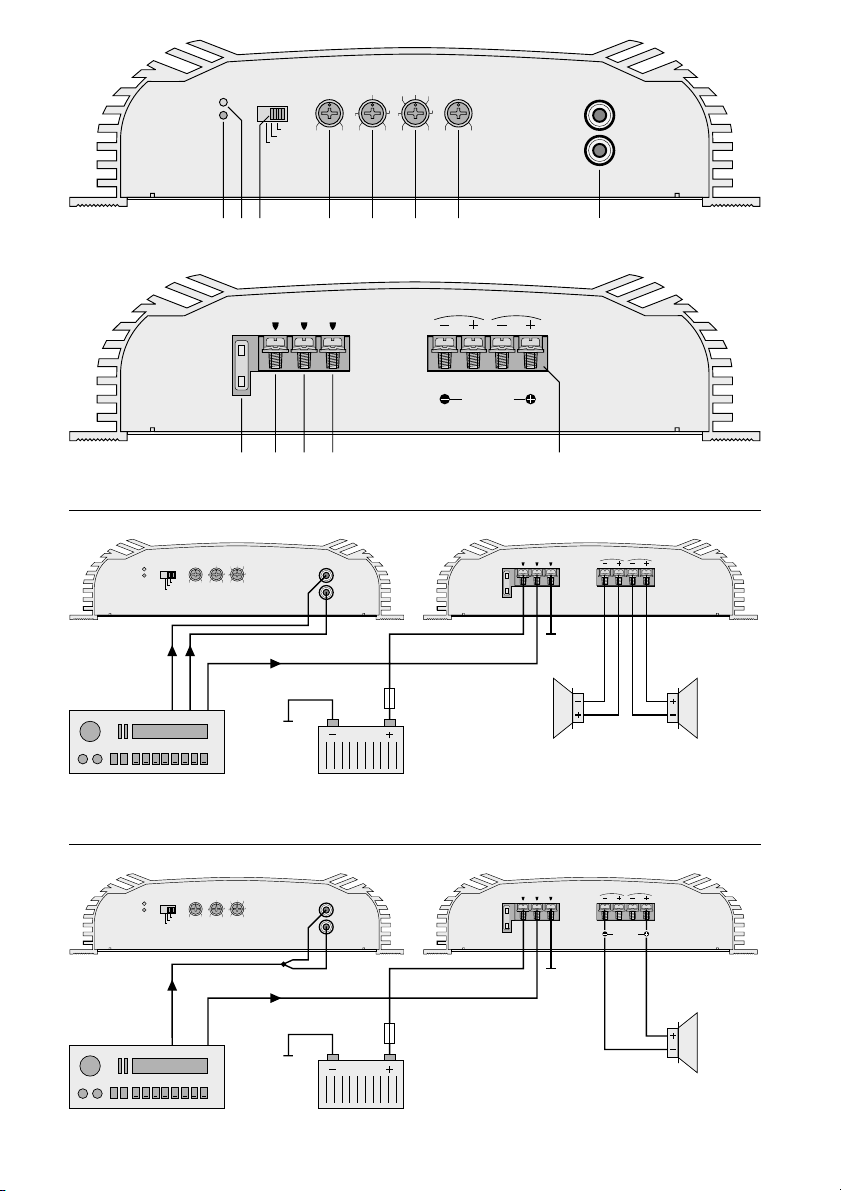
The complete connection is shown in fig. 3 or fig. 4.
6.1 Power supply
6.1.1 Terminal “+12v” (10)
Connect the terminal “+12v” via a cable with a cross
section of min. 10mm2(e.g. CPC-100/RT by CAR-
POWER) to the positive terminal of the car battery. To
protect the newly laid 12V cable against short circuit,
insert in any case an additional fuse (15A for HPB-502
or 25A for HPB-1002) very close to the battery (fig. 3).
To stabilize the operating voltage for the booster
and the resulting power increase as well as sound im-
provement, a power capacitor is recommended (e.g.
CPS-500 or CPS-1000 by CARPOWER).
6.1.2 Terminal “ground” (12)
Connect the terminal “ground” via a cable of a cross
section of min. 10mm2(e.g. CPC-100/SW by CAR-
POWER) to the ground of the car or directly to the
negative terminal of the car battery. To avoid ground
loops, the ground of the car radio must be placed at
the point where also the booster is grounded.
6.1.3 Terminal “rem” (11)
The car HiFi booster is switched on and off by a +12V
control voltage at the terminal “rem”. Connect the ter-
minal “rem” to the 12V output of the car radio (connec-
tion for a motor antenna, if necessary to be connected
in parallel with the motor antenna).
If no 12V output is provided at the car radio, the
terminal “rem” must get +12V via the ignition lock or a
separate switch.
6.2 Inputs
Connect both inputs “line in” (8) via cables with phono
connectors to the corresponding line outputs of the
car radio (fig. 3). If no line outputs are provided on the
car radio, alternatively connect the speaker outputs of
the car radio via a corresponding transformer (e.g.
FGA-20 by CARPOWER) to the booster inputs.
If the booster in bridge operation is to drive a
speaker for the right or left channel, connect both
inputs “line in” in common via a Y cable (e.g. CBA-
25/SW by CARPOWER) to the line output of the right
or left channel at the car radio – also see fig. 4. (How-
ever, if a mono subwoofer is driven in bridge operation,
connect the inputs separately, as shown in fig. 3.)
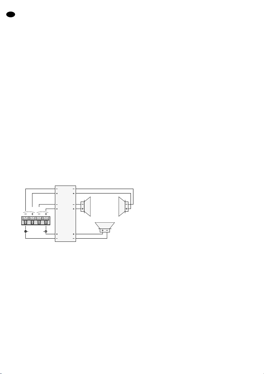
6.3 Speakers
It is possible to use full range speakers, mid-high
range speakers, or bass speakers or a subwoofer. In
2-channel operation the booster can drive the speak-
ers for the left and right channels or in bridge operation
with increased output power it can drive the speaker
for a channel or a subwoofer.
Important! All speakers must be connected with
2 poles, i.e. without common ground
connection.
When choosing suitable speakers, pay in
any case attention to their mechanical
and electrical capability in connection
with the booster power applied (also see
specifications of the booster page 11).
6.3.1 2-channel operation
The greatest output power is reached when connect-
ing 2Ωspeakers or a speaker group with a total impe-
dance of 2Ωper channel (e.g. two 4Ωspeakers or
four 8Ωspeakers connected in parallel). However, it is
also possible to connect individual 4Ωor 8Ωspeakers
in which case the output power is reduced.
GB
9

GB
10
Connect the speakers to the terminals “speakers” (13)
– also see fig. 3:
R
-
= negative pole right speaker
R+ = positive pole right speaker
L
-
= negative pole left speaker
L+ = positive pole left speaker
6.3.2 Bridge operation
In bridge operation the impedance of the connected
speaker or the total impedance of a speaker group
must not be lower than 4Ω! Connect the speaker to
the terminals “speakers” (13), in which case the let-
tering “bridge mode” has to be observed – also see
fig. 4:
R
-
= negative pole
R+ = remains unconnected
L
-
= remains unconnected
L+ = positive pole
6.3.3 Tri-mode
A subwoofer in bridged mono operation and two mid-
high range speakers in 2-channel operation are driven
in the tri-mode. For this purpose a suitable tri-mode
crossover network is necessary. The impedance of the
connected speakers must not be lower than 4Ω!
The tri-mode is possible for both models HPB-502
and HPB-1002. Due to the required power reserve this
kind of operation, however, is only recommended for
model HPB-1002.
Connect the speakers via a suitable tri-mode cross-
over network to the terminals “speakers” (13):
Tri-mode ➄
7 Setting into Operation
Prior to the first switching-on, switch on the cor-
responding filter and coarsely adjust the cross-
over frequency (chapter 7.1) so that the speakers
are not overloaded by a frequency range that
might be too large. It is also recommended to
check the complete wiring of the car HiFi booster
once again for correctness. Only then connect the
negative terminal of the car battery again.
7.1 Switching-on the filter and adjusting the
crossover frequency
According to the speaker type used, switch on the re-
quired filter with the switch “selecter” (3):
For full range speakers set the switch to position
FLAT. Thus, all filters are switched off and the controls
“lowpass” (5) and “highpass” (6) have no function. The
booster reproduces the entire frequency range.
For mid-high range speakers set the switch to posi-
tion HIGHPASS. The high pass is switched on, and the
low frequencies are thus suppressed. First coarsely
adjust the crossover frequency with the control “high-
pass” (6)*. The control “lowpass” (5) has no function.
For bass speakers or a subwoofer set the switch to
position LOWPASS. The low pass is switched on, and
the medium as well as high frequencies are suppres-
sed. First coarsely adjust the crossover frequency with
the control “lowpass (5)*. The control “highpass” (6)
has no function.
*For a guidance observe the frequency range of the speak-
ers used. The fine adjustment is made with the correspond-
ing meters after the level adjustment.
7.2 Matching the level
Note To keep the interfering radiation by the electric
system of the car as low as possible, the output
level of the signal source should be 1.5V as a
minimum.
1) Turn the control “level” (4) to position “8v”.
2) Switch on the car HiFi system completely. The red
LED “protection” (1) on the booster lights up for ap-
prox. 3 seconds and then the green LED “power”
(2) lights up continuously. The signal is only switch-
ed to the outputs after 3 more seconds (switch-on
delay).
3) Adjust the signal source, e.g. the car radio, to the
maximal not distorting volume (in most cases ap-
prox. 3/4of the maximum).
4) Turn up the control “level” (4) so that just no distor-
tions occur.
5) If further boosters are used in the car HiFi system,
reduce the levels of the channels which are too
high to match the volumes of all channels with each
other. (In case the total volume should not reach
the desired level, insert more powerful boosters
into the channels which are too poor.)
6) In case of model HPB-1002 the bass frequencies
can be boosted with the control “bass boost” (7).
!
bridge mode
speakers
RL
Subwoofer
min. 4Ω
Tri-Mode
crossover
network
right
channel
in out
sub-
woofer
in out
left
channel
in out L
min. 4ΩR
min. 4Ω

8 Trouble Shooting
If there is no sound after switching on the car HiFi
system, locate the fault more precisely by means of
the two LEDs “power” (2) and “protection” (1).
8.1 No LED lights up
1) Check the fuse (9) on the car HiFi booster and the
additional fuse on the car battery. Replace defec-
tive fuses. Only use fuses with the values as indi-
cated (HPB-502: 15A each, HPB-1002: 25Aeach).
Do not insert a fuse of a higher value under any cir-
cumstances. The booster can be damaged, and the
guarantee will be cancelled.
2) Check the 12V power supply cable as well as the
ground cable for interruption and correct connec-
tion.
3) Check at the terminal “rem” (11) of the car HiFi
booster if +12V is present. If not, remove the cable
at the terminal “rem” and bridge the terminals “rem”
(11) and “+12v” (10) for a short time. If the car HiFi
booster is switched on now, the error is due to the
missing control voltage. Check the 12V output of
the car radio (or the separate switch or the ignition
lock) and check the corresponding connection
cable to the booster.
8.2 Green LED “power” lights up
1) Check the connection cable from the signal source
to the car HiFi booster. Are the plugs correctly
connected? Is the cable interrupted?
2) Check the signal source. Is the signal source
switched on? Have the correct outputs been used?
Is the signal source defective?
3) Check the speaker cables for interruption.
4) Check the connected speakers.
8.3 Red LED “protection” lights up
The booster is protected with a protection circuit
against short circuit at the speaker outputs and against
overheating. If the protection circuit responds, the red
LED “protection” (1) lights up. Check the speaker
cables for short circuit and check the impedance of the
speakers (2-channel operation 2Ωper channel as a
minimum, bridge operation 4Ωas a minimum). The
reason may also be due to an insufficient heat dissipa-
tion (ventilation).After the error has been eliminated or
after cooling off, the booster switches on again auto-
matically.
GB
11
HPB-502 HPB-1002
Output power
total power
bridge operation at 4Ωspeaker
2-channel operation at 2Ωspeaker
2-channel operation at 4Ωspeaker
250WMAX
1 x 150WRMS
2 x 80WRMS
2 x 50WRMS
500WMAX
1 x 300WRMS
2 x 150WRMS
2 x 100WRMS
Frequency range 20–20000Hz 20–20000Hz
Min. speaker impedance
2-channel operation
bridge operation 2 x 2Ω
1 x 4Ω2 x 2Ω
1 x 4Ω
Input impedance 20kΩ20kΩ
Input sensitivity 0.11–8.8V 0.11–8.8V
Channel separation 65dB 65dB
S/N ratio 85dB 85dB
THD < 0.2% < 0.2%
Filters
low pass
high pass 40–460Hz
65–4500Hz 40–460Hz
65–4500Hz
Power supply 11–16V /20A 11–16V /40A
Admissible ambient temperature 0–40°C 0–40°C
Dimensions 260 x 63 x 165mm 260 x 63 x 285mm
Weight 2.2kg 3kg
According to the manufacturer.
Subject to change.
9 Specifications
Bass boost —0–18dB

Ouvrez le présent livret page 3 de manière à visua-
liser les éléments et branchements.
Table des matières
1 Eléments et branchements . . . . . . . . . . . . . 12
2 Conseils de sécurité . . . . . . . . . . . . . . . . . . 12
3 Attention: Volumes élevés . . . . . . . . . . . . . 13
4 Possibilités d’utilisation . . . . . . . . . . . . . . . 13
5 Montage . . . . . . . . . . . . . . . . . . . . . . . . . . . . 13
6 Branchements . . . . . . . . . . . . . . . . . . . . . . . 13
6.1 Alimentation . . . . . . . . . . . . . . . . . . . . . . . . . . 13
6.1.1 Branchement “+12V” . . . . . . . . . . . . . . . . . . 13
6.1.2 Branchement “ground” . . . . . . . . . . . . . . . . 13
6.1.3 Branchement “rem” . . . . . . . . . . . . . . . . . . . 13
6.2 Entrées . . . . . . . . . . . . . . . . . . . . . . . . . . . . . . 13
6.3 Haut-parleurs . . . . . . . . . . . . . . . . . . . . . . . . . 13
6.3.1 Mode 2 canaux . . . . . . . . . . . . . . . . . . . . . . 14
6.3.2 Mode bridgé . . . . . . . . . . . . . . . . . . . . . . . . 14
6.3.3 Tri-mode . . . . . . . . . . . . . . . . . . . . . . . . . . . 14
7 Fonctionnement . . . . . . . . . . . . . . . . . . . . . . 14
7.1 Allumage du filtre et réglage de la fréquence
de coupure . . . . . . . . . . . . . . . . . . . . . . . . . . . 14
7.2 Adaptation des niveaux . . . . . . . . . . . . . . . . . 14
8 Problèmes . . . . . . . . . . . . . . . . . . . . . . . . . . . 15
8.1 Aucune LED ne brille . . . . . . . . . . . . . . . . . . . 15
8.2 La LED verte “power” brille . . . . . . . . . . . . . . 15
8.3 La LED rouge “protection” brille . . . . . . . . . . . 15
9 Caractéristiques techniques . . . . . . . . . . . . 15
1 Eléments et branchements
1LED “protection”: brille lorsque le circuit de protec-
tion est activé:
1. pendant trois secondes environ après la mise
sous tension (temporisation d’allumage)
2. lorsqu’une des sorties HP(13) est court-circuitée
3. en cas de surchauffe de l’amplificateur
2Témoin de fonctionnement Power
3Interrupteur pour les filtres
LOWPASS: passe-bas allumé (pour le subwoofer)
HIGHPASS: passe-haut allumé (pour les HP mé-
dium-aigus)
FLAT: aucun filtre allumé (pour les HP large
bande)
4Potentiomètre de réglage pour l’adaptation du ni-
veau d’entrée
5Potentiomètre de réglage pour la fréquence de
coupure du passe-bas
6Potentiomètre de réglage pour la fréquence de
coupure du passe-haut
7(uniquement pour HPB-1002) potentiomètre “bass
boost” pour élever les fréquences graves
8Entrées Ligne (G/D = L/R)
9Fusible 15A (HPB-502) ou 25A (HPB-1002);
tout fusible hors service doit être remplacé par un
fusible du même type
10 Branchement pour l’alimentation +12V
11 Entrée commande “rem” pour allumer l’amplifica-
teur HiFi embarquée via une tension 12V
12 Branchement “ground” masse
13 Branchements haut-parleurs
2 Conseils de sécurité
Cet amplificateur répond à la norme européenne
89/336/CEE relative à la compatibilité électroma-
gnétique.
●Lorsque vous reliez l’amplificateur HiFi embarquée
à la batterie de la voiture, soyez très prudent; en cas
de court-circuit, des courants très élevés et donc
dangereux circulent. C’est pourquoi avant tout bran-
chement, n’oubliez pas de dévisser la borne moins
de la batterie.
●L’appareil doit être solidement fixé dans un endroit
mécaniquement stable dans la voiture pour éviter
qu’il ne se dévisse et ne se transforme en projectile
dangereux.
●Pendant son fonctionnement, il peut devenir très
chaud; il est recommandé de ne pas placer à proxi-
mité d’objets sensibles à la chaleur et de ne pas le
toucher pendant son fonctionnement.
●Pour le nettoyer, utilisez un chiffon sec et souple, en
aucun cas de produits chimiques ou d’eau.
●Nous déclinons toute responsabilité en cas de dom-
mage si l’appareil est utilisé dans un but autre que
celui pour lequel il a été conçu, s’il n’est pas correc-
tement utilisé, branché ou réparé d’une manière ap-
propriée.
●Lorsque l’appareil est définitivement retiré du ser-
vice, vous devez le déposer dans une usine de recy-
clage adaptée.
F
B
CH
12

3 Attention: Volumes élevés
●Ne réglez jamais le volume trop fort. Des volumes
trop élevés peuvent endommager l’ouïe.
●L’oreille humaine s’habitue à des volumes élevés et,
après un certain temps, ne les perçoit plus de la
même manière. C’est pourquoi nous vous recom-
mandons de ne pas augmenter le volume une fois
que vous y êtes habitué.
●Ne réglez jamais le volume du système audio trop
fort: vous devez pouvoir toujours entendre les bruits
extérieurs, par exemple, une ambulance.
4 Possibilités d’utilisations
Les amplificateurs HPB-502 et HPB-1002 sont spé-
cialement conçus pour des installations de HiFi em-
barquée et peuvent faire fonctionner deux haut-par-
leurs large bande. Grâce aux filtres de fréquences in-
tégrés, on peut réaliser, avec un amplificateur
supplémentaire, un système actif 2 voies avec deux
haut-parleurs de médium-aigu et deux haut-parleurs
de grave ou un subwoofer. Pour maintenir une puis-
sance de sortie importante, l’amplificateur peut faire
fonctionner un haut-parleur en mode bridgé.
5 Montage
Lorsque vous choisissez le lieu d’installation de l’ap-
pareil, respectez les points suivants:
●Le cordon d’alimentation 12V reliant la batterie à
l’amplificateur HiFi embarquée devrait être aussi
court que possible; il est préférable d’utiliser des
câbles haut-parleurs plus longs et par contre un cor-
don d’alimentation plus court.
●Le câble de la masse reliant l’amplificateur au châs-
sis du véhicule devrait être aussi court que possible.
●Pour permettre une évacuation correcte de la cha-
leur dégagée par l’amplificateur HiFi embarquée,
veillez à assurer une ventilation suffisante.
●A cause des forces qui résultent lors du freinage
brusque, l’amplificateur peut se transformer en pro-
jectile dangereux, veillez à le fixer correctement à un
endroit mécaniquement stable.
●Les fusibles et les réglages doivent être faciles
d’accès.
Pour le montage, usez les 4 trous de fixation prévus
sur le dissipateur. Montez-le à l’endroit approprié en
fixant les 4 vis livrées.
6 Branchements
●Le branchement de l’amplificateur HiFi embarquée
au système électrique de la voiture ne doit être ef-
fectué que par un technicien habilité.
●Pour éviter tout court-circuit éventuel lors de l’instal-
lation, et ainsi tout dégât, dévissez impérativement
la borne moins de la batterie de la voiture.
●Placez les câbles de telle sorte que leur isolation ne
soit pas endommagée.
Les schémas 3 et 4 présentent l’ensemble des bran-
chements.
6.1 Alimentation
6.1.1 Branchement “+12V” (10)
Reliez la borne “+12v” via un cordon d’une section de
10mm2au moins (par exemple CPC-100/RT de CAR-
POWER) à la borne plus de la batterie du véhicule.
Pour protéger le nouveau câble 12V contre tout court-
circuit, il faut impérativement insérer un fusible supplé-
mentaire (15A pour le HPB-502, 25A pour le HPB-
1002) à proximité immédiate de la batterie (schéma 3).
Pour stabiliser la tension de fonctionnement pour
l’amplificateur et donc l’augmentation de puissance et
l’amélioration du son, nous vous recommandons d’uti-
liser un condensateur de puissance (par exemple
CPS-500 ou CPS-1000 de CARPOWER).
6.1.2 Branchement “ground” (12)
Reliez la borne “ground” via un cordon d’une section
de 10mm2au moins (par exemple CPC-100/SW de
CARPOWER) à la masse du véhicule ou directement
à la borne moins de la batterie du véhicule. Pour éviter
tout bouclage de masse, la masse de l’autoradio doit
être placée là où l’amplificateur est également à la
masse.
6.1.3 Branchement “rem” (11)
L’amplificateur HiFi embarquée est allumé et éteint via
une tension de +12V à la borne “rem”. Reliez la borne
“rem” à la sortie 12V de l’autoradio (branchement pour
une antenne moteur, branchez éventuellement en par-
allèle avec l’antenne moteur).
Si aucune sortie 12V n’existe sur l’autoradio, la
borne “rem” doit recevoir la tension +12V via un inter-
rupteur séparé ou la clé de contact.
6.2 Entrées
Reliez les deux entrées “line in” (8) via un cordon RCA
aux sorties Ligne correspondantes de l’autoradio
(schéma 3). Si sur l’autoradio, il n’y a pas de sorties Li-
gne, reliez les sorties haut-parleurs de l’autoradio al-
ternativement via un transformateur correspondant
(par exemple FGA-20 de CARPOWER) aux entrées
de l’amplificateur.
Si l’amplificateur en mode bridgé doit faire fonc-
tionner un haut-parleur pour le canal droit ou gauche,
reliez les deux entrées “line in” ensemble, via un cor-
don en Y (par exemple CBA-25/SW de CARPOWER)
à la sortie Ligne du canal droit ou gauche de l’autora-
dio – voir aussi schéma 4. (Si en mode bridgé, un sub-
woofer mono est utilisé, connectez les entrées séparé-
ment, comme indiqué sur le schéma 3.)
6.3 Haut-parleurs
Il est possible de faire fonctionner des haut-parleurs
large bande, des haut-parleurs de médium-aigu ou de
grave ou un subwoofer. En mode 2 canaux, l’amplifi-
cateur peut faire fonctionner des haut-parleurs pour le
canal droit et le canal gauche; en mode bridgé avec
une puissance de sortie supérieure, il peut comman-
der un haut-parleur pour un canal ou un subwoofer.
Important! tous les haut-parleurs doivent être bran-
chés avec 2 pôles, c’est-à-dire sans
masse commune.
F
B
CH
13

F
B
CH
14
Lors de la sélection des haut-parleurs ap-
propriés, veillez à prendre en compte la
capacité mécanique et électrique du haut-
parleur selon la puissance appliquée de
l’amplificateur (voir aussi les caractéri-
stiques techniques, page 15).
6.3.1 Mode 2 canaux
La puissance de sortie est la plus élevée lorsque des
haut-parleurs 2Ωou un groupe de haut-parleurs avec
une impédance totale de 2Ωpar canal sont reliés (par
exemple deux haut-parleurs 4Ωou quatre haut-par-
leurs 8Ωbranchés en parallèle). Il est également pos-
sible de brancher des haut-parleurs individuels 4Ωou
8Ω, la tension de sortie est alors moindre.
Reliez les haut-parleurs aux bornes “speakers” (13),
voir aussi schéma 3:
R
-
= pôle moins HP droit
R+ = pôle plus HP droit
L
-
= pôle moins HP gauche
L+ = pôle plus HP gauche
6.3.2 Mode bridgé
En mode bridgé, l’impédance du haut-parleur relié ou
l’impédance totale d’un groupe de haut-parleurs ne
doit pas être inférieure à 4Ω! Reliez le haut-parleur
aux bornes “speakers” (13) au niveau, veillez au
repère “bridge mode” (voir aussi schéma 4):
R
-
= pôle moins
R+ = reste libre
L
-
= reste libre
L+ = pôle plus
6.3.3 Tri-mode
Le mode de fonctionnement tri-mode permet de faire
fonctionner un subwoofer en mode bridgé mono et
deux haut-parleurs de médium aigu en mode 2 ca-
naux. Pour cela un filtre tri-mode est nécessaire;
l’impédance des haut-parleurs reliés ne doit pas être
inférieure à 4Ω!
Ce mode de fonctionnement est possible sur les
deux modèles HPB-502 et HPB-1002; en raison de la
réserve de puissance nécessaire, nous vous conseil-
lons d’utiliser ce mode uniquement avec le modèle
HPB-1002.
Reliez les haut-parleurs aux bornes “speakers” (13)
via un filtre tri-mode approprié:
Tri-mode ➄
7 Fonctionnement
Avant la première mise sous tension, allumez le
filtre et réglez la fréquence de coupure grossière-
ment (chapitre 7.1) de manière à éviter toute
surcharge des haut-parleurs par une plage de fré-
quences trop grande. Vérifiez l’ensemble du câ-
blage de l’amplificateur HiFi embarquée encore
une fois, seulement après reconnectez la borne
moins de la batterie de voiture.
7.1 Allumage du filtre et réglage de la fré-
quence de coupure
Selon le type de haut-parleur utilisé, allumez le filtre
nécessaire avec l’interrupteur “selecter” (3):
Pour des haut-parleurs large bande, mettez l’inter-
rupteur sur la position FLAT. Tous les filtres sont ainsi
déconnectés, les réglages “lowpass” (5) et “highpass”
(6) sont sans fonction. L’amplificateur reproduit la tota-
lité de la plage de fréquences.
Pour des haut-parleurs de médium-aigu: mettez l’in-
terrupteur sur HIGHPASS: le filtre passe-haut est al-
lumé, les fréquences basses sont ainsi diminuées.
Réglez d’abord grossièrement la fréquence de
coupure avec le réglage “highpass” (6)*; le réglage
“lowpass” (5) est hors fonction.
Pour les haut-parleurs de grave ou un subwoofer:
mettez l’interrupteur sur LOWPASS: le filtre passe-bas
est allumé, les fréquences aiguës et médianes sont di-
minuées. Réglez d’abord grossièrement la fréquence
de coupure avec le réglage “lowpass” (5)*; le réglage
“highpass” (6) est hors fonction.
*Pour effectuer le réglage, reportez-vous à la bande pas-
sante des haut-parleurs utilisés. Le réglage plus précis se
fait une fois les niveaux réglés avec des instruments de
mesure correspondants.
7.2 Adaptation des niveaux
Remarque Pour réduire au mieux les interférences
générées par le système électrique du
véhicule, le niveau de sortie de la source
audio doit être de 1,5V au moins.
1) Tournez le réglage “level” (4) sur la position “8v”.
2) Allumez l’ensemble de l’installation HiFi embar-
quée. Sur l’amplificateur, la LED rouge “protection”
(1) brille pendant 3 secondes environ puis la LED
verte “power” (2) brille en continu. Le signal est
commuté sur les sorties, 3 secondes après (tempo-
risation d’entrée).
3) Réglez la source audio (par exemple l’autoradio)
sur le volume maximal ne présentant pas de distor-
sion (en général 3/4du maximum).
4) Tournez le réglage “level” (4) tant qu’il n’y a pas de
distorsion.
5) Si plusieurs amplificateurs sont présents dans l’in-
stallation HiFi embarquée, réduisez les niveaux de
tous canaux trop forts pour adapter le volume de
l’ensemble des canaux entre eux. (Si le volume to-
tal ne devrait pas atteindre le niveau souhaité,
placez des amplificateurs plus puissants dans les
canaux trop faibles).
6) En cas de modèle HPB-1002 les fréquences gra-
ves peuvent être élevées avec le potentiomètre
“bass boost” (7).
!
bridge mode
speakers
RL
Subwoofer
min. 4Ω
Tri-Mode
crossover
network
right
channel
in out
sub-
woofer
in out
left
channel
in out L
min. 4ΩR
min. 4Ω

9 Caractéristiques techniques
8 Problèmes
Si lors de l’allumage de l’installation HiFi embarquée,
aucun son n’est audible, les LEDs “power” (2) et “pro-
tection” (1) peuvent vous aider à localiser le problème.
8.1 Aucune LED ne brille
1) Vérifiez le fusible (9) sur l’amplificateur HiFi embar-
quée et le fusible supplémentaire de la batterie de
la voiture. Remplacez tout fusible défectueux. N’u-
tilisez que des fusibles avec les valeurs indiquées
(HPB-502: 15A, HPB-1002: 25A), en aucun cas de
valeur supérieure. L’amplificateur peut être endom-
magé, dans ce cas, la garantie devient caduque.
2) Contrôlez le cordon d’alimentation 12V et le câble
masse; vérifiez les connexions et la solidité du
câble.
3) Vérifiez si la tension +12V est bien présente à la
borne “rem” (11) de l’amplificateur HiFi embarquée.
Si ce n’est pas le cas, retirez le câble de la borne
“rem” et bridgez brièvement les bornes “rem” (11) et
“+12v” (10). Si l’amplificateur s’allume, le problème
réside dans l’absence de tension d’alimentation.
Vérifiez la sortie 12V de l’autoradio (ou l’interrup-
teur séparé ou la clé) et également le cordon de
liaison à l’amplificateur.
8.2 La LED verte “power” brille
1) Vérifiez le câble de liaison entre l’amplificateur HiFi
embarquée et la source. Les fiches sont-elles bien
insérées? Le câble est-il interrompu?
2) Vérifiez la source. La source est-elle allumée? Sont
les sorties correctes utilisées? La source est-elle
défectueuse?
3) Vérifiez si le câble haut-parleur ne présente pas
d’interruption.
4) Vérifiez les haut-parleurs reliés.
8.3 La LED rouge “protection” brille
L’amplificateur est protégé par un circuit de protection
contre les courts-circuits aux sorties haut-parleurs et
contre les surchauffes. La LED rouge “protection” (1)
s’allume lorsque ce circuit est activé. Vérifiez le câble
haut-parleur (court-circuit?) et l’impédance des haut-
parleurs (mode 2 canaux: 2Ωpar canal minimum,
mode bridgé 4Ωminimum). Le problème peut égale-
ment venir d’une mauvaise évacuation de la chaleur
dégagée par l’appareil (ventilation). Une fois le pro-
blème solutionné ou après le refroidissement de l’ap-
pareil, ce dernier redémarre automatiquement.
F
B
CH
15
D’après les données du constructeur.
Tout droit de modification réservé.
HPB-502 HPB-1002
Puissance de sortie
puissance totale
mode bridgé HP 4Ω
mode 2 canaux HP 2Ω
mode 2 canaux HP 4Ω
250WMAX
1 x 150WRMS
2 x 80WRMS
2 x 50WRMS
500WMAX
1 x 300WRMS
2 x 150WRMS
2 x 100WRMS
Bande passante 20–20000Hz 20–20000Hz
Impédance HP minimale
mode 2 canaux
mode bridgé 2 x 2Ω
1 x 4Ω2 x 2Ω
1 x 4Ω
Impédance d’entrée 20kΩ20kΩ
Sensibilité d’entrée 0,11–8,8V 0,11–8,8V
Séparation des canaux 65dB 65dB
Rapport signal/bruit 85dB 85dB
Taux de distorsion < 0,2% < 0,2%
Filtre
passe-haut
passe-bas 40–460Hz
65–4500Hz 40–460Hz
65–4500Hz
Alimentation 11–16V /20A 11–16V /40A
Température d’utilisation admisseble 0–40°C 0–40°C
Dimensions 260 x 63 x 165mm 260 x 63 x 285mm
Poids 2,2kg 3kg
Elevation des fréquences graves —0–18dB

Vi preghiamo di aprire completamente la pagina 3.
Così vedrete sempre gli elementi di comando e i
collegamenti descritti.
Indice
1 Elementi di comando e collegamenti . . . . . 16
2 Avvertenza di sicurezza . . . . . . . . . . . . . . . . 16
3 Attenzione col volume alto . . . . . . . . . . . . . 17
4 Possibilità d’impiego . . . . . . . . . . . . . . . . . . 17
5 Montaggio . . . . . . . . . . . . . . . . . . . . . . . . . . . 17
6 Collegamenti . . . . . . . . . . . . . . . . . . . . . . . . 17
6.1 Alimentazione corrente . . . . . . . . . . . . . . . . . 17
6.1.1 Collegamento “+12v” . . . . . . . . . . . . . . . . . . 17
6.1.2 Collegamento “ground” . . . . . . . . . . . . . . . . 17
6.1.3 Collegamento “rem” . . . . . . . . . . . . . . . . . . 17
6.2 Ingressi . . . . . . . . . . . . . . . . . . . . . . . . . . . . . 17
6.3 Altoparlanti . . . . . . . . . . . . . . . . . . . . . . . . . . . 17
6.3.1 Collegamento a 2 canali . . . . . . . . . . . . . . . 17
6.3.2 Collegamento a ponte . . . . . . . . . . . . . . . . . 18
6.3.3 Modalità “Tri” . . . . . . . . . . . . . . . . . . . . . . . . 18
7 Messa in funzione . . . . . . . . . . . . . . . . . . . . 18
7.1 Attivare il filtro ed impostare la frequenza
di taglio . . . . . . . . . . . . . . . . . . . . . . . . . . . . . . 18
7.2 Adattare il livello . . . . . . . . . . . . . . . . . . . . . . . 18
8 Eliminazione di difetti . . . . . . . . . . . . . . . . . 18
8.1 Non si accende nessun LED . . . . . . . . . . . . . 18
8.2 Il LED verde “Power” rimane acceso . . . . . . . 19
8.3 Il LED rosso “Protection” rimane acceso . . . . 19
9 Dati tecnici . . . . . . . . . . . . . . . . . . . . . . . . . . 19
1 Elementi di comando e collegamenti
1Spia “protection” si accende con il circuito di prote-
zione attivato:
1. per 3 secondi ca. dopo l’accensione (ritardo
dell’accensione)
2. se una delle uscite per altoparlanti (13) è corto-
circuitata
3. se l’amplificatore è surriscaldato
2Spia di funzionamento
3Selettore dei filtri
LOWPASS: passabasso attivato (per subwoofer)
HIGHPASS: passaaalto attivato (per midrange/
tweeter)
FLAT: nessun filtro è attivato (per altopar-
lanti a banda larga)
4Potenziometro dell’adattamento del livello d’in-
gresso
5Potenziometro per la frequenza di taglio del passa-
basso
6Potenziometro per la frequenza di taglio del pas-
saalto
7(solamente per HPB-1002) regolatore “bass boost”
per aumentare i bassi
8Ingressi Line (L/R)
9Fusibile 15 A (HPB-502) e 25 A (HPB-1002);
sostituire un fusibile bruciato solo con uno dello
stesso tipo
10 Contatto per il collegamento tensione +12V
11 Ingresso di comando “rem” per attivare il booster
mediante una tensione di 12V
12 Contatto massa “ground”
13 Contatti per altoparlanti
2 Avvertenza di sicurezza
Quest’apparecchio corrisponde alla direttiva CE
89/336/CEE sulla compatibilità elettromagnetica.
●Usare particolare cura nel collegamento con la bat-
teria dell’auto. Nel caso di cortocircuiti ci possono
essere delle correnti molto alte. Prima del collega-
mento scollegare il polo negativo della batteria.
●Prevedere un posto solido e montare il booster con
cura per evitare che si possa staccare, diventando
pericoloso in caso di incidente.
●Durante il funzionamento, il booster può riscaldarsi
molto. Non mettere nelle sue vicinanze oggetti sen-
sibili al calore e non toccare il booster.
●Per la pulizia usare solo un panno asciutto; non im-
piegare in nessun caso prodotti chimici o acqua.
●Nel caso di uso improprio, di comandi sbagliati, di
collegamenti errati o di riparazione scorretta non si
assume nessuna responsabilità per eventuali danni.
●Se si desidera eliminare l’apparecchio definitiva-
mente, consegnarlo per lo smaltimento ad un’istitu-
zione locale per il riciclaggio.,
I
16

3 Attenzione col volume alto
●Non alzare troppo il volume. Il volume troppo alto
può danneggiare l’udito.
●L’orecchio si abitua al volume alto e dopo un certo
periodo non se ne accorge più. Pertanto conviene
non aumentare il volume alto impostato inizial-
mente.
●Mentre si guida l’auto, i segnali di ambulanze ecc.
non devono essere coperti dal volume dell’impianto
audio.
4 Possibilità d’impiego
I booster HPB-502 e HPB-1002 sono previsti per im-
pianti hi-fi nelle auto e possono comandare 2 altopar-
lanti a larga banda. Con i filtri integrati e con un boo-
ster supplementare è possibile realizzare un sistema
attivo a 2 vie con due midrange/tweeter e con rispetti-
vamente due woofer o un subwoofer. Per aumentare
la potenza d’uscita, il booster può, con collegamento a
ponte, pilotare un solo altoparlante.
5 Montaggio
Prima di scegliere un posto per il montaggio occorre
considerare i seguenti punti.
●Il cavo di alimentazione 12V dalla batteria al booster
deve essere il più corto possibile. È preferibile usare
lunghi cavi per gli altoparlanti e tenere corto il cavo
di alimentazione.
●Anche il cavo della massa dal booster al telaio della
macchina deve essere il più corto possibile.
●Per poter dissipare il calore sprigionato dal booster
deve essere garantita una ventilazione sufficiente.
●Per le forze che si manifestano nelle frenate, il punto
di montaggio deve essere meccanicamente stabile.
●I fusibili e i regolatori devono essere accessibili.
Per il montaggio usare i quattro fori nel dissipatore.
Montare il booster saldamente usando quattro viti.
6 Collegamenti
●Il collegamento del booster con la rete di bordo
dev’essere eseguito da personale qualificato.
●Per evitare cortocircuiti durante l’installazione, prima
del montaggio scollegare il polo negativo della bat-
teria auto.
●Sistemare i cavi in modo tale che l’isolamento non
possa subire danni.
Le figure 3 e 4 illustrano i collegamenti.
6.1 Alimentazione corrente
6.1.1 Collegamento +12v (10)
Collegare l’ingresso “+12v” con il polo positivo della
batteria auto usando un cavo di 10mm2minimo (p.es.
CPC-100/RT del programma CARPOWER). Per pro-
teggere il nuovo cavo +12V contro i cortocircuiti inse-
rire assolutamente un fusibile (15A per HPB-502 e
25A per HPB-1002) nella diretta vicinanza della batte-
ria (fig. 3).
Per stabilizzare la tensione d’esercizio per il booster e
quindi l’aumento di potenza nonché il miglioramento
sonoro, si consiglia l’uso di un condensatore di po-
tenza (p.es. CPS-500 o CPS-1000 del programma
CARPOWER).
6.1.2 Collegamento “ground” (12)
Collegare l’ingresso “ground” con la massa dell’auto o
direttamente con il polo negativo della batteria, usando
un cavo di 10mm2minimo (p.es. CPC-100/SW del
programma CARPOWER). Per evitare l’effetto di anelli
di terra, la massa dell’autoradio deve essere collegata
allo stesso punto in cui è collegata la massa del
booster.
6.1.3 Collegamento “rem” (11)
Il booster viene acceso e spento da una tensione di
comando di +12V tramite il contatto “rem”. Collegare il
contatto “rem” con l’uscita 12V dell’autoradio (collega-
mento per un’antenna motorizzata; eventualmente
collegamento in parallelo con tale antenna).
Se l’autoradio non dispone di un’uscita 12V, colle-
gare il contatto “rem” +12V con l’accensione della
macchina o con un interruttore separato.
6.2 Ingressi
Collegare i due ingressi “line in” (8) del booster con le
uscite Line dell’autoradio usando cavi cinch (fig. 3). Se
l’autoradio non possiede nessun’uscita Line, le uscite
per gli altoparlanti possono essere collegate con gli in-
gressi del booster mediante un trasformatore (p.es.
FGA-20 del programma CARPOWER).
Se il booster collegato a ponte deve pilotare un al-
toparlante per il canale di destra oppure di sinistra,
collegare i due ingressi “line in” con l’uscita Line del
canale di destra o di sinistra dell’autoradio, servendosi
di un cavo ad Y (p.es. CBA-25/SW del programma
CARPOWER) – vedi anche fig. 4. (Se con un collega-
mento a ponte viene usato un subwoofer mono, ese-
guire i collegamento in modo separato come illustrato
in fig. 3).
6.3 Altoparlanti
Si possono usare altoparlanti a larga banda, mid-
range/tweeter e woofer o un subwoofer. In caso di col-
legamento a 2 canali, il booster può pilotare gli alto-
parlanti per i canali di destra e di sinistra; con funzio-
namento a ponte invece può pilotare, con potenza
d’uscita aumentata, l’altoparlante di un canale oppure
un subwoofer.
Importante! Tutti gli altoparlanti devono essere col-
legati a due poli, cioè senza massa co-
mune!
Nella scelta degli altoparlanti adatti oc-
corre fare assolutamente attenzione
alla loro potenza meccanica e elettrica
in relazione alla potenza finale usata
(vedi anche i dati tecnici del booster a
pagina 19).
6.3.1 Collegamento a 2 canali
La massima potenza d’uscita si ottiene collegando al-
toparlanti a 2Ωoppure un gruppo di altoparlanti con
un’impedenza globale di 2Ωper canale (p.es. due al-
I
17

toparlanti a 4Ωo 4 altoparlanti a 8Ω, collegati in pa-
rallelo). Si possono collegare anche singoli altoparlanti
a 4Ωo a 8Ω; ma in questo caso la potenza d’uscita è
ridotta.
Collegare gli altoparlanti ai morsetti “speakers” (13) –
vedi anche fig. 3:
R
-
= negativo dell’altoparlante destro
R+ = positivo dell’altoparlante destro
L
-
= negativo dell’altoparlante sinistro
L+ = positivo dell’altoparlante sinistro
6.3.2 Collegamento a ponte
Nel collegamento a ponte, l’impedenza dell’altopar-
lante collegato o l’impedenza globale di un gruppo di
altoparlanti non deve essere inferiore a 4Ω! Collegare
l’altoparlante ai morsetti “speakers” (13), tenendo
conto della scritta “bridge mode” – vedi anche fig. 4:
R
-
= negativo
R+ = libero
L
-
= libero
L+ = positivo
6.3.3 Modalità “Tri”
Nella modalità “Tri” si usano un subwoofer mono a
ponte e due midrange/tweeter in collegamento a 2
canali. Per fare ciò occorre un particolare filtro tri. L’im-
pedenza degli altoparlanti collegati non deve essere
inferiore a 4Ω!
La modalità “Tri” è possibile per entrambi i modelli,
HPB-502 e HPB-1002. In considerazione della po-
tenza richiesta si consiglia comunque tale modalità
solo per il modello HPB-1002.
Collegare gli altoparlanti con i morsetti “speakers” (13)
tramite un filtro tri:
Modalità “Tri” ➄
7 Messa in funzione
Prima della prima accensione, attivare il relativo
filtro ed impostare in modo grossolano la fre-
quenza di taglio (cap. 7.1) per non sovraccaricare
gli altoparlanti con una banda eventualmente
troppo grande. Inoltre controllare l’intero cablag-
gio del booster. Solo allora ricollegare il polo ne-
gativo della batteria auto.
7.1 Attivare il filtro ed impostare la frequenza
di taglio
Aseconda del tipo di altoparlanti, attivare il filtro richie-
sto tramite il selettore “selecter” (3):
Per gli altoparlanti a larga banda portare il selettore
in posizione FLAT. In questo modo, tutti i filtri sono di-
sattivati e i regolatori “lowpass” (5) e “highpass” (6)
sono privi di funzioni. Il booster riproduce l’intera
banda di frequenze.
Per i midrange/tweeter portare il selettore in posi-
zione HIGHPASS. È attivato il passaalto, e le fre-
quenze basse vengono soppresse. Impostare la fre-
quenza di taglio in modo grossolano con il regolatore
“highpass” (6)*. Il regolatore “lowpass” (5) è senza fun-
zione.
Per i woofer o per un subwoofer, portare il selettore
in posizione LOWPASS. È attivato il passabasso, e le
frequenze medie e alte vengono soppresse. Im-
postare la frequenza di taglio in modo grossolano con
il regolatore “lowpass” (5)*. Il regolatore “highpass” (6)
è senza funzione.
*Tener conto della banda passante degli altoparlanti usati.
La regolazione fine avverrà al termine dell’impostazione del
livello con l’aiuto di appositi strumenti.
7.2 Adattare il livello
Un consiglio: Per tener possibilmente bassi i disturbi
provocati dal sistema elettrico della
macchina, il livello d’uscita della sor-
gente dovrebbe essere non inferiore a
1,5V.
1) Girare il regolatore “level” (4) in posizione “8v”.
2) Accendere completamente l’impianto hi-fi dell’auto.
Sul booster si accende per 3 secondi ca. il LED
rosso “protection” (1) e quindi rimane acceso il LED
verde “power” (2). Il segnale passa alle uscite solo
dopo altri 3 secondi (ritardo dell’accensione).
3) Regolare la sorgente, p. es. l’autoradio, sul volume
massimo senza che vi siano delle distorsioni (ge-
neralmente a 3/4del massimo).
4) Aprire il regolatore “level” (4) al punto da escludere
appena delle distorsioni.
5) Se l’impianto hi-fi contiene altri booster, ridurre il li-
vello dei canali troppo forti per adattare il volume di
tutti canali. (Se in questo caso, il volume globale
non dovesse raggiungere il livello desiderato, mon-
tare dei booster più potenti nei canali troppo de-
boli.).
6) Per il modelo HPB-1002 i bassi possono essere
alzati con il regolatore “bass boost” (7).
8 Eliminazione di difetti
Se dopo l’accensione dell’impianto audio dell’automo-
bile non si sente niente, si può localizzare il difetto os-
servando i due LED “power” (2) e “protection” (1).
8.1 Non si accende nessun LED
1) Controllare il fusibile (9) sul booster e quello vicino
alla batteria dell’auto. Sostituire i fusibili difettosi.
Usare solo fusibili con i valori indicati (HPB-502:
15A; HPB-1002: 25 A). Non inserire in nessun caso
un valore maggiore. Il booster potrebbe subire dei
danni e la garanzia non sarebbe più valida.
2) Controllare il cavo di alimentazione +12V nonché il
cavo di massa. I collegamenti devono essere cor-
retti e non ci deve essere nessun’interruzione.
!
bridge mode
speakers
RL
Subwoofer
min. 4Ω
Tri-Mode
crossover
network
right
channel
in out
sub-
woofer
in out
left
channel
in out L
min. 4ΩR
min. 4Ω
I
18

3) Verificare se al morsetto “rem” (11) del booster è
presente una tensione di +12V. In caso negativo,
staccare il cavo dal morsetto “rem” e ponticellare
brevemente i morsetti “rem” (11) e “+12v” (10). Se il
booster si accende ora, significa che manca la ten-
sione di comando. Controllare l’uscita 12V dell’au-
toradio (oppure l’interruttore separato o l’accen-
sione della macchina) nonché il cavo di collega-
mento verso il booster.
8.2 Il LED verde “power” rimane acceso
1) Controllare i cavi di collegamento dalla sorgente
fino al booster. I connettori sono inseriti bene? È in-
terrotto il collegamento?
2) Controllare la sorgente. È accesa? Le uscite sono
quelle giuste? È difettosa la sorgente?
3) Controllare se ci sono interruzioni nei cavi degli al-
toparlanti.
4) Controllare gli altoparlanti collegati.
8.3 Il LED rosso “protection” rimane acceso
Il booster è equipaggiato con un circuito di protezione
contro i cortocircuiti alle uscite per altoparlanti nonché
contro il surriscaldamento. Se il circuito di protezione
reagisce, il LED rosso “protection” (1) rimane acceso.
Controllare che non vi sia un cortocircuito nei cavi
degli altoparlanti e verificare l’impedenza degli altopar-
lanti (min. 2Ωper canale con funzionamento a
2 canali, min. 4Ωcon funzionamento a ponte). La
causa può essere anche una ventilazione insuffi-
ciente. Dopo l’eliminazione del guasto o dopo il raf-
freddamento, il booster si accende automaticamente.
I
19
Dati forniti dal costruttore.
Con riserva di modifiche tecniche.
HPB-502 HPB-1002
Potenza d’uscita
Potenza globale
a ponte con altoparlanti 4 Ω
a 2 canali con altoparlanti 2 Ω
a 2 canali con altoparlanti 4 Ω
250WMAX
1 x 150WRMS
2 x 80WRMS
2 x 50WRMS
500WMAX
1 x 300WRMS
2 x 150WRMS
2 x 100WRMS
Banda passante 20–20000Hz 20–20000Hz
Impedenza min. altoparlanti
a 2 canali
a ponte 2 x 2Ω
1 x 4Ω2 x 2Ω
1 x 4Ω
Impedenza d’ingresso 20kΩ20kΩ
Sensibilità d’ingresso 0,11–8,8V 0,11–8,8V
Separazione canali 65dB 65dB
Rapporto S/R 85dB 85dB
Fattore di distorsione < 0,2% < 0,2%
Filtri
passabasso
passaalto 40–460Hz
65–4500Hz 40–460Hz
65–4500Hz
Alimentazione 11–16V /20A 11–16V /40A
Temperatura d’impiego 0–40°C 0–40°C
Dimensioni 260 x 63 x 165mm 260 x 63 x 285mm
Peso 2,2kg 3kg
Aumento di bassi —0–18dB
9 Dati tecnici

HPB-502 / HPB-1002
Lees aandachtig de onderstaande veiligheidsvoor-
schriften, alvorens de apparatuur in gebruik te nemen.
Mocht u bijkomende informatie over de bediening van
de apparatuur nodig hebben, lees dan de Duitse,
Engelse, Franse, of Italiaanse tekst van deze hand-
leiding.
1 Veiligheidsvoorschriften
Het toestel is in overeenstemming met de EU-Richtlijn
89/336/EEG voor elektromagnetische compatibiliteit.
●De aansluiting van de eindversterker van de auto-
installatie op de autobatterij dient zorgvuldig te ge-
beuren. Bij kortsluiting kunnen gevaarlijk hoge stro-
men ontstaan. Maak daarom voor de aansluiting
van de versterker de negatieve klem van de auto-
batterij in ieder geval los.
●De eindversterker moet vast en deskundig op een
mechanisch stabiele plaats in de auto gemonteerd
worden, zodat hij niet kan loskomen en op die
manier een gevaarlijk projectiel gaat vormen.
●Tijdens het gebruik kan de eindversterker zeer warm
worden. Plaats daarom geen warmtegevoelige
voorwerpen in de buurt, en raak de eindversterker
tijdens het gebruik niet aan.
●Gebruik voor de reiniging uitsluitend een droge,
zachte doek. Gebruik in geen geval chemicaliën of
water.
●In geval van ongeoorloofd of verkeerd gebruik, fou-
tieve bediening, verkeerde aansluiting of herstelling
door een niet-gekwalificeerd persoon vervalt de
garantie bij eventuele schade.
●Wanneer het toestel definitief uit bedrijf genomen
wordt, bezorg het dan voor verwerking aan een
plaatselijk recyclagebedrijf.
2 Opgelet bij hoge geluidsvolumes
●Stel het volume nooit te hoog in. Uitzonderlijk hoge
volumes kunnen het gehoor beschadigen.
●Het gehoor raakt aangepast aan hoge volumes die
na een tijdje niet meer zo hoog lijken. Draai het
volume daarom niet verder open, zelfs nadat u
eraan gewend bent.
●Zorg ervoor dat het geluidsvolume van de hifi-instal-
latie in de auto niet te hoog staat, waardoor geluids-
signalen, bijvoorbeeld die van een ambulance, niet
meer hoorbaar zouden zijn.
3 Montage
Hou bij de keuze van de montageplaats in elk geval
rekening met de volgende punten:
●De voedingsspanningskabel (12V) van de batterij
naar de eindversterker van de auto-installatie moet
zo kort mogelijk zijn. Het is voordeliger om langere
luidsprekerkabels te gebruiken en een kortere
voedingsspanningskabel.
●Zorg er ook voor dat de massakabel van de eindver-
sterker naar het koetswerk zo kort mogelijk is.
●Zorg voor voldoende ventilatie om de hitte die in de
eindversterker ontstaat, af te voeren.
●Door de krachten die tijdens het remmen optreden,
moet de eindversterker op een mechanisch stabiele
plaats vastgeschroefd worden.
●De zekeringen en de regelaar moeten makkelijk
toegankelijk zijn.
Gebruik voor de montage de vier openingen van de
behuizing. Monteer de booster met behulp van vier
schroeven op een geschikte plaats.
4 Aansluitingen
●De eindversterker mag uitsluitend door gekwalifi-
ceerd personeel op het elektrische circuit van de
auto aangesloten worden.
●Om schade door eventuele kortsluiting tijdens de in-
stallatie te vermijden, koppelt u best de negatieve
klem los van de autobatterij, alvorens de aansluiting
uit te voeren.
●Breng de nodige kabels zo aan, dat de isolatie ervan
niet beschadigd kan worden.
NL
B
20
This manual suits for next models
1
Table of contents
Languages:
Other Monacor Extender manuals