manuals.online logo
Brands
  1. Home
  2. •
  3. Brands
  4. •
  5. Monogram
  6. •
  7. Kitchen Appliance
  8. •
  9. Monogram ZIB240P Instruction manual

Monogram ZIB240P Instruction manual

Technical Data
Pub. No. 31-51547-1 1547S
N.D. 06E-1794
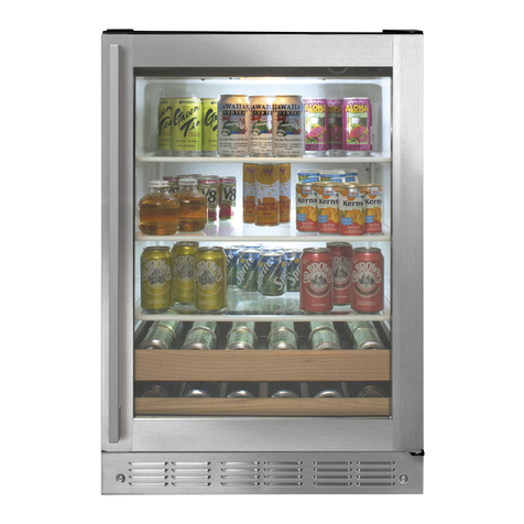
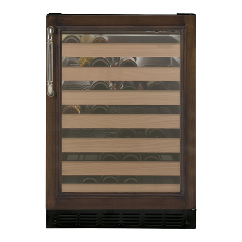
ZIB240P/ZIBS240P Bar Unit
INSTALLATION
Clearance must be provided for air circulation
AT TOP ........................................................................................................................0
AT SIDES ....................................................................................................................0
AT REAR .........................................................................................................1 INCH
DOOR FRONT TO PROTRUDE
FROM CABINETS ............................................................... MIN. 1-3/4 INCH
197D5892P003
NOTE: Remove Jumper J1 and J4. Jumpers J2 and J3 remain installed.
Three Serviceable thermistors: inside the unit, on the right wall, above
the top shelf, near the back wall.
Inside the unit, in the freezer compartment, on the right wall, near the
front, near the top.
Inside the unit, in the freezer compartment, behind the evaporator cover,
in the upper right corner of the evaporator.
Service Mode information on back of page.
Capillary
Dryer
Compressor
Process Tube
Condenser
Evaporator
06E-1794A
POWER SUPPLY BOARD
WIRING DIAGRAM
SERVICE BOARD - JUMPER CONFIGURATION
BLACK
WHITE
GREEN/YELLOW
RED
1
2
3
4
K2
5
6
WHITE
BLACK
WATER
VALVE
BLACK
WHITE
1
2
K3
LIGHT
15W
BLACK
WHITE
1
2
K4
FUSE
LINK
DC SIDE
K5
1
2
3
4
BROWN
BROWN or BLUE
BLUE or BROWN
BLUE
FF NTC
EVAP
NTC
K6
1
2
3
BLACK
BLUE
BROWN
WHITE
BLUE
RED
DAMPER
K9
1
2
BLACK or BROWN
BLACK or BLUE
FZ NTC
K11
1
2
3
4
BROWN
BLUE
LOGIC
BOARD WHITE
BLACK
K13
1
3
BROWN
BLUE
CLOSE (COM)
+18V
OPEN (COM)
+5V
CLK
DATA
COM
FAN (COM)
+12V
NEUTRAL
GND
LINE
NEUTRAL
NEUTRAL
LIGHT
NEUTRAL
HEATER
FILL TB
HEATER
DEF
HEATER
EVAP. FAN
NOTE: () = OPERATING DC VOLTAGES
180-190 Ohms
REED DOOR SW.
COM
COM
COM
BLACK
WHITE
GREEN/YELLOW
RED
120V
POWER
CORD
BLUE
PTCR
OVER
LOAD
COMPRESSOR
1
2
3
4
K1
RED
AC SIDE
LINE
NEUTRAL
GND
COMP
COND. FAN
BLUE
BLACK GREY
WHITE
WHITE
3.5W
100W
K14
HEATER (COM)
+12V1
3
RED
WHITE
DAMPER
HEATER
2W
WHITE
WHITE
KEY PLUG
N/C
1
2
3
4
5
6
WHITE
RED
BLACK
ICE
MAKER
N/C
N/C
1
2
3
4
5
6
KEY PLUG
KEY PLUG
K1
K2
K3
K4
K6
K11 K13
K9 K5
DAMPER
LOGIC BD.
EVAP.
FAN
DMPR.
HEATER
FF + EVAP NTCFZ NTC
J2 J1
J4
J3
POWER
ICE MAKER
LIGHT
FILL TB + DEF
HEATERS
AC SIDEDC SIDE
K14
RUN
CAP.
DRAIN TB
HEATER 3.67W
FAN
HEATER
NOTE: WATTAGES @ 115V
5.05W
06E-1794B
DISCONNECT POWER CORD BEFORE SERVICING
IMPORTANT - RECONNECT ALL GROUNDING DEVICES
All parts of this appliance capable of conducting electrical current
are grounded. If grounding wires, screws, straps, clips, nuts or
washers used to complete a path to ground are removed for
service, they must be returned to their original position and
properly fastened.
ELECTRICAL SPECIFICATIONS
Temperature Control ...................................................................................39°F
Electrical Rating: 120V AC 60Hz .................................................... 2.0 Amp
Maximum Current Leakage .............................................................. 0.50 mA
Maximum Ground Path Resistance .........................................0.14 Ohms
NO LOAD PERFORMANCE
Control Position
and Ambient Temperature of: 70°F 90°F
Fresh Food, °F ................................................................ 33-45 33-45
Ice compartment, °F ...................................................(-5)-6 (-5)-6
Percent Running Time, % ........................................ 35-45 50-65
REFRIGERATION SYSTEM
Refrigerant Charge (R134a) ................................................. 3.2 ounces
Compressor ................................................................................ 590 BTU/hr
Minimum Compressor Capacity
Vacuum .......................................................................................21 inches
Minimum Equalized Pressure
@70°F ...............................................................................................37 PSIG
@90°F ...............................................................................................40 PSIG
IMPORTANT SAFETY NOTICE
This information is intended for use by individuals possessing
adequate backgrounds of electrical, electronic and mechanical
experience. Any attempt to repair a major appliance may result in
personal injury and property damage. The manufacturer or seller
cannot be responsible for the interpretation of this information,
nor can it assume any liability in connection with its use.
Compressor, fans, and heaters disabled. When
first entered display “on” for 5 seconds and exit
Service mode. Next time entered display “OFF”
for 5 seconds and exit Service mode.
“P” on display if OK. “F” on display means
problem found.
The incandescent light, all LED’s, and numeric
segments will illuminate for 5 seconds and then
off for 1 second.
Checks each thermistor. The following
is displayed for 1 second and then the
instantaneous temperature for 5 minutes or
until any other key is pressed:
“FF” = Fresh Food
“EP” = Evaporator
“IC” = Icemaker
The damper will open for 5 seconds then close.
Compressor and condenser fan on 100% of the
time for 20 minutes. The 4-minute delay before
restarting the compressor will be overridden;
there will be no time delay to restart the
compressor in the Service Mode.
Turns on defrost cycle 5 minutes and then off.
Causes a system reset and exits Service Mode.
Exits out of Service mode and display “out” for
3 seconds.
Checks each switch. The following is displayed
for 1 second for each switch:
“dor” = Door
“dd” = Double Drawers
Each of these is followed by displaying “ 0 ”.
The display will increment with each switch
closure.
Toggles the lights and switchable glass on for 20
seconds then off.
Toggles fresh food fan On and Off by pressing
On/Off button.
Change time value of delay from 1 to 8 minutes
(with 1-minute increments). Store result in
EEPROM.
Degree sign flashes off every
10 seconds for half a second.
Data string sent from PSB to LB, back
to PSB and checked for accuracy.
If no Icemaker, a “- -” is displayed.
If thermistor is electrically opened
or shorted “bAd” is displayed. The
sampling rate for each thermistor in
this mode is 1 second. Next button
push terminates timeout.
When opening, display “OPn”. When
closing, display “CLS”.
Display “run” when the compressor is
on. If a warmer / colder key is pressed
exit back into the Service keeping
the compressor on. If any other key
is pressed, turn compressor off and
display “OFF” for 3 seconds.
Displays “on” when on. Next button
push terminates timeout. Displays
“OFF” for 3 seconds when off.
Starts factory default operating mode.
Resumes previous operating mode.
Once 9 is reached the display goes
back to “ 0 ” and starts over. Press any
key to move to the next switch and
after the last switch exit.
Display “on” when they are on, and
“OFF” for 3 seconds when they are off
and exit.
Display “on” when the fan is running.
Display “OFF” for three seconds when
off and exit.
Press the On/Off button to increment
the time. Once 8 is reached the display
goes back to “ 1 ” and starts over. Once
you have incremented to the new
set delay, press the warmer or colder
button to store value in EEPROM before
exiting the mode. If unit is not a bar
unit display “- -”.
Display Diagnostics Results Comments
Code
0 1 Showroom Mode
0 2 Data Communication
Check
0 6 Display Test
0 7 Sensor System Test
1 0 Damper Test
1 2 100% Run Time
1 4 Defrost Test
1 5 Reset
1 6 Exit Diagnostic Mode
2 1 Switch Test
2 2 Lights and
Switchable Glass
2 3 DC Fresh Food Fan
2 4 Delay for Evaporator Fan
and Damper After Defrost
Service Modes
1547S
197D5892P003
TO ENTER SERVICE MODE: Press and hold the (+), (-), and (ON/OFF) buttons simultaneously for 5 seconds. Display will show 3 numbers.
First is the model number, verify this is 4 for the Bar unit. Second and third are software version. Use the (+) and (-) buttons to toggle
through display codes. Use the (ON/OFF) button to activate diagnostic check for specific code.
TO EXIT SERVICE MODE: Toggle to code 15 and press the (ON/OFF) button. This will reset the system to factory settings.
This manual suits for next models

1

Other Monogram Kitchen Appliance manuals

Monogram ZDWI240HII User manual

Monogram

Monogram ZDWI240HII User manual

Monogram ZDWI240 User manual

Monogram

Monogram ZDWI240 User manual

Monogram ZEP30 User manual

Monogram

Monogram ZEP30 User manual

Monogram ZDWR240NBS User manual

Monogram

Monogram ZDWR240NBS User manual

Monogram ZDBI240HCII User manual

Monogram

Monogram ZDBI240HCII User manual

Monogram ZDBI240 User manual

Monogram

Monogram ZDBI240 User manual

Monogram ZKR36R User manual

Monogram

Monogram ZKR36R User manual

Monogram JXSOUSV1 User manual

Monogram

Monogram JXSOUSV1 User manual

Monogram ZGU484NG User manual

Monogram

Monogram ZGU484NG User manual

Monogram ZDBR240NBS User manual

Monogram

Monogram ZDBR240NBS User manual

Popular Kitchen Appliance manuals by other brands

Kalorik Kitchen Originals PIM 40573 instruction manual

Kalorik

Kalorik Kitchen Originals PIM 40573 instruction manual

Russell Hobbs 21480-56 Instructions & recipes

Russell Hobbs

Russell Hobbs 21480-56 Instructions & recipes

Kenwood TYPE FGP20 Instructions and recipe ideas

Kenwood

Kenwood TYPE FGP20 Instructions and recipe ideas

TEFAL Turbo Cuisine Maxi manual

TEFAL

TEFAL Turbo Cuisine Maxi manual

Hello Kitty KT5246 Owner's manual and recipe book

Hello Kitty

Hello Kitty KT5246 Owner's manual and recipe book

Vitek VT-2491 W instruction manual

Vitek

Vitek VT-2491 W instruction manual

Cuisinart CJE-1000 user manual

Cuisinart

Cuisinart CJE-1000 user manual

Vinotemp Element EL-BF23F owner's manual

Vinotemp

Vinotemp Element EL-BF23F owner's manual

KITCHENIE KI-799 instructions

KITCHENIE

KITCHENIE KI-799 instructions

Korona 23710 instruction manual

Korona

Korona 23710 instruction manual

KitchenAid 5KSMSFTA manual

KitchenAid

KitchenAid 5KSMSFTA manual

Dash DSM100 Instruction manual & recipe guide

Dash

Dash DSM100 Instruction manual & recipe guide

Bosch Styline HomeProfessional MFQ4 Series INFORMATION FOR USE

Bosch

Bosch Styline HomeProfessional MFQ4 Series INFORMATION FOR USE

Kasanova BYE000002NOC instruction manual

Kasanova

Kasanova BYE000002NOC instruction manual

Inalsa Twister instruction manual

Inalsa

Inalsa Twister instruction manual

Smeg CPF9IPAN Original instructions

Smeg

Smeg CPF9IPAN Original instructions

Ninja QB3001UKS instructions

Ninja

Ninja QB3001UKS instructions

Presto DiamondCoat Tilt’nDrain instructions

Presto

Presto DiamondCoat Tilt’nDrain instructions

manuals.online logo
manuals.online logoBrands
  • About & Mission
  • Contact us
  • Privacy Policy
  • Terms and Conditions

Copyright 2025 Manuals.Online. All Rights Reserved.