manuals.online logo
Brands
  1. Home
  2. •
  3. Brands
  4. •
  5. Monogram
  6. •
  7. Ventilation Hood
  8. •
  9. Monogram ZV48R User manual

Monogram ZV48R User manual

INSTALLATION
INSTRUCTIONS
30”, 36” and 48”
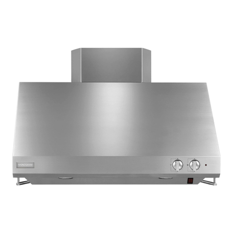
Professional Restaurant Style Vent Hoods
MONOGRAM.COM
231-2000856 Rev. 0
Safety Information
READ AND SAVE THESE INSTRUCTIONS
BEFORE YOU BEGIN
Read these instructions completely and carefully.
ŶIMPORTANT— Save these instructions
for local inspector’s use.
ŶIMPORTANT— Observe all governing
codes and ordinances.
ŶNote to Installer — Be sure to leave these
instructions with the Consumer.
ŶNote to Consumer — Keep these instructions with
your Owner’s Manual for future reference.
ŶSkill Level — Installation of this appliance requires
basic mechanical and electrical skills.
ŶCompletion Time — 1 to 3 Hours.
Ŷ3URSHULQVWDOODWLRQLVWKHUHVSRQVLELOLW\RIWKHLQVWDOOHU
3URGXFWIDLOXUHGXHWRLPSURSHULQVWDOODWLRQLVQRW
covered under the warranty.
Ŷ)RU0RQRJUDPORFDOVHUYLFHLQ\RXUDUHDYLVLW
monogram.com or call 1.800.444.1845.
Ŷ)RU0RQRJUDPVHUYLFHLQ&DQDGDYLVLWmonogram.ca
or call 1.800.561.3344.
Ŷ)RU0RQRJUDP3DUWVDQG$FFHVVRULHVYLVLW
monogram.com/use-and-care/parts or call
1.800.444.1845..
CAUTION Due to the weight and size of these
vent hoods and to reduce the risk of personal injury
RUGDPDJHWRWKHSURGXFW TWO PEOPLE ARE
REQUIRED FOR PROPER INSTALLATION.
WARNING To reduce the risk of fire or electrical
VKRFNGRQRWXVHWKLVUDQJHKRRGZLWKDQ\H[WHUQDO
VROLGVWDWHVSHHGFRQWUROGHYLFH$Q\VXFKDOWHUDWLRQ
from original factory wiring could result in damage to
the unit and/or create an electrical safety hazard.
TO REDUCE THE RISK OF FIRE, USE ONLY
METAL DUCTWORK.
WARNING 725('8&(7+(5,6.2)),5(
(/(&75,&$/6+2&.25,1-85<723(56216
2%6(59(7+()2//2:,1*
$8VHWKLVXQLWRQO\LQWKHPDQQHULQWHQGHGE\WKH
PDQXIDFWXUHU,I\RXKDYHDQ\TXHVWLRQVFRQWDFW
the manufacturer.
%%HIRUHVHUYLFLQJRUFOHDQLQJWKHXQLWVZLWFKWKH
power off at the service panel and lock the service
disconnecting means to prevent the power from
EHLQJVZLWFKHGRQDFFLGHQWDOO\:KHQWKHVHUYLFH
GLVFRQQHFWLQJPHDQVFDQQRWEHORFNHGVHFXUHO\
IDVWHQDSURPLQHQWZDUQLQJGHYLFHVXFKDVDWDJ
to the service panel.
CAUTION )25*(1(5$/9(17,/$7,1*86(
21/<'212786(72(;+$867+$=$5'286
0$7(5,$/6(;3/26,9(0$7(5,$/6259$3256
WARNING 725('8&(7+(5,6.2)),5(
(/(&75,&$/6+2&.25,1-85<723(56216
2%6(59(7+()2//2:,1*
Ŷ,QVWDOODWLRQZRUNDQGHOHFWULFDOZLULQJPXVWEHGRQHE\
qualified person(s) in accordance with all applicable
FRGHVDQGVWDQGDUGVLQFOXGLQJILUHUDWHGFRQVWUXFWLRQ
Ŷ6XIILFLHQWDLULVQHHGHGIRUSURSHUFRPEXVWLRQDQG
H[KDXVWLQJRIJDVHVWKURXJKWKHIOXHFKLPQH\RIIXHO
EXUQLQJHTXLSPHQWWRSUHYHQWEDFNGUDIWLQJ)ROORZ
the heating equipment manufacturer’s guidelines
DQGVDIHW\VWDQGDUGVVXFKDVWKRVHSXEOLVKHGE\
WKH1DWLRQDO)LUH3URWHFWLRQ$VVRFLDWLRQ1)3$WKH
$PHULFDQ6RFLHW\IRU+HDWLQJ5HIULJHUDWLRQDQG$LU
&RQGLWLRQLQJ(QJLQHHUV$6+5$(DQGWKHORFDOFRGH
DXWKRULWLHV:KHQDSSOLFDEOHLQVWDOODQ\PDNHXS
(replacement) air system in accordance with local
building code requirements. Visit GEAppliances.com
for available makeup air solutions.
Ŷ:KHQFXWWLQJRUGULOOLQJLQWRZDOOVRUFHLOLQJVGRQRW
damage electrical wiring and other hidden utilities.
Ŷ'XFWHGV\VWHPVPXVWDOZD\VEHYHQWHGWRWKHRXWGRRUV
Ŷ/RFDOFRGHVYDU\,QVWDOODWLRQRIHOHFWULFDOFRQQHFWLRQV
and grounding must comply with applicable codes.
,QWKHDEVHQFHRIORFDOFRGHVWKHYHQWVKRXOGEH
LQVWDOOHGLQDFFRUGDQFHZLWK1DWLRQDO(OHFWULFDO&RGH
$16,1)3$RUODWHVWHGLWLRQ
CAUTION To reduce risk of fire and to properly
H[KDXVWDLUEHVXUHWRGXFWDLURXWVLGH²GRQRWYHQW
H[KDXVWDLULQWRVSDFHVZLWKLQZDOOVRUFHLOLQJVRULQWR
DWWLFVFUDZOVSDFHVRUJDUDJHV
31-2000856 Rev. 0 3
Consignes de sécurité
LISEZ ET CONSERVEZ CES INSTRUCTIONS
AVANT DE COMMENCER
Veuillez lire attentivement ces instructions dans leur
intégralité.
ŶIMPORTANT— Veuillez conserver ces
instructions pour afin que l’inspecteur local puisse s’y référer.
ŶIMPORTANT— Respectez tous les codes
réglementaires et les règlements.
ŶNote destinée à l’installateur²$VVXUH]YRXVGHODLVVHU
ces instructions au client.
ŶNote destinée au client — Veuillez conserver ces
instructions avec votre manuel utilisateur afin de pouvoir
vous y référer ultérieurement.
ŶNiveau de compétence — l’installation de cet appareil
requiert des compétences en matière de mécanique et
d’électricité.
ŶDurée d’assemblage — 1 à 3 heures.
Ŷ/¶LQVWDOODWLRQLQFRPEHjO¶LQVWDOODWHXU6LOHSURGXLWFRQQDvW
XQHGpIDLOODQFHGXHjXQHLQVWDOODWLRQLQDSSURSULpHOD
garantie ne s’applique pas.
Ŷ3RXUOHVHUYLFHORFDO0RQRJUDPGDQVYRWUHUpJLRQYLVLWH]
monogram.com ou appelez le 1.800.444.1845.
Ŷ3RXUOHVHUYLFH0RQRJUDPDX&DQDGDYLVLWH]
monogram.ca ou appelez le 1.800.561.3344.
Ŷ3RXUOHVSLqFHVHWDFFHVVRLUHV0RQRJUDPYLVLWH]
monogram.com/use-and-care/parts ou appelez le
1.800.444.1845.
ATTENTION À cause du poids et de la taille de
ces hottes et pour reduire le risque de blessures et de
GRPPDJHV IL FAUT DEUX PERSONNES POUR FAIRE
L’INSTALLATION CORRECTEMENT.
AVERTISSEMENT
3RXUUpGXLUHOHULVTXHG¶LQFHQGLH
RXGHFKRFpOHFWULTXHLOQHIDXWSDVXWLOLVHUFHWWHKRWWH
DYHFXQUpJXODWHXUGHYLWHVVHpOHFWURQLTXHH[WHUQH7RXWH
modification de ce type du branchement d’usine peute
endommager l’appareil ou créer un risque de choc électrique.
AFIN DE RÉDUIRE LE RISQUE D’INCENDIE, N’UTILISEZ
QUE DES CONDUITS MÉTALLIQUES.
AVERTISSEMENT
32855e'8,5(/(5,648(
'¶,1&(1',('(&+2&e/(&75,48(28'(%/(6685(6
,/)$872%6(59(5/(65(*/(668,9$17(6
$8WLOLVH]FHWDSSDUHLOXQLTXHPHQWGHODPDQLpUpSUpYXHSDU
OHIDEULFDQW(QFDVGHTXHVWLRQFRQVXOWH]OHIDEULFDQW
%$YDQWWRXWHLQWHUYHQWLRQRXQHWWR\DJHFRXSH]O¶DOLPHQWDWLRQ
électrique au disjoncteur et verrouillez le panneau du
disjoncteur pour éviter la mise sous tension accidentelle. S’il
Q¶HVWSDVSRVVLEOHGHYHUURXLOOHUOHSDQQHDXGXGLVFRQFWHXU
attachez un placard ou une étiquette très visible au panneau.
ATTENTION 81,48(0(17¬'(6),16'(
9(17,/$7,211(/¶87,/,6(=3$63285e9$&8(5
'(668%67$1&(6'$1*(5(86(6'(60$7e5,$8;
(;3/26,)628'(69$3(856
AVERTISSEMENT
$),1'(5e'8,5(/(5,648(
'¶,1&(1',(/(6e/(&752&87,21628/(6%/(6685(6
$8;3(56211(69(8,//(=5(63(&7(5&(48,68,7
Ŷ/¶LQVWDOODWLRQHWOHFkEODJHpOHFWULTXHGRLYHQWrWUHHIIHFWXpV
SDUXQHRXSOXVLHXUVSHUVRQQHVTXDOLILpHVFRQIRUPpPHQW
jWRXVOHVFRGHVHWWRXWHVOHVQRUPHVDSSOLFDEOHVGRQW
FHX[FRQFHUQDQWODUpVLVWDQFHDXIHXGHVFRQVWUXFWLRQV
Ŷ8QHTXDQWLWpG¶DLUVXIILVDQWHHVWQpFHVVDLUHjXQH
combustion et une évacuation appropriées des gaz par
le conduit d’évacuation (cheminée) de l’équipement à
combustible pour éviter tout refoulement. Suivez les
directives et normes de sécurité du fabricant de l’appareil
FKDXIIDQWFRPPHFHOOHVSXEOLpHVSDUOD1DWLRQDO
)LUH3URWHFWLRQ$VVRFLDWLRQ1)3$SDUO¶$PHULFDQ
6RFLHW\IRU+HDWLQJ5HIULJHUDWLRQDQG$LU&RQGLWLRQLQJ
(QJLQHHUV$6+5$(HWSDUOHVDXWRULWpVORFDOHV/HFDV
pFKpDQWLQVWDOOH]XQV\VWqPHGHFRPSHQVDWLRQG¶DLU
UHPSODFHPHQWFRQIRUPpPHQWDX[FRQGLWLRQVGHVFRGHV
ORFDX[GXEkWLPHQW9LVLWH]OHVLWHGEAppliances.com
SRXUFRQQDvWUHOHVVROXWLRQVRIIHUWHVHQPDWLqUHGHV\VWqPH
de compensation d’air.
Ŷ/RUVTXHYRXVHIIHFWXH]GHVGpFRXSHVRXTXHYRXVSHUFH]
XQPXURXXQSODIRQGQ¶HQGRPPDJH]SDVOHFkEODJH
électrique ou tout autre réseau d’alimentation caché.
Ŷ/¶DLUGHVYHQWLODWHXUVGLVSRVDQWGHFRQGXLWVG¶DpUDWLRQGRLW
WRXMRXUVrWUHpYDFXpYHUVO¶H[WpULHXU
Ŷ/HVFRGHVORFDX[SHXYHQWYDULHU/¶LQVWDOODWLRQGH
branchements électriques et la mise à la terre doivent
rWUHFRQIRUPHVDX[FRGHVHQYLJXHXU/HVpYDFXDWLRQV
GRLYHQWrWUHLQVWDOOpHVFRQIRUPpPHQWjODGHUQLqUHpGLWLRQ
GX&RGH(OHFWULTXH1DWLRQDO$16,1)3$1R
ATTENTION Il faut prendre soin d’installer un conduit
YHUVO¶H[WpULHXUSRXUUpGXLUHOHULVTXHG¶LQFHQGLHHWSRXYRLU
évacuer l’air correctement. Il ne faut pas évacuer l’air dans
O¶HVSDFHHQWUHOHVSDURLVG¶XQPXUXQSODIRQGRXXQJUHQLHU
un espace sanitaire ou un garage.
431-2000856 Rev. 0
Información sobre Seguridad
LEA Y GUARDE ESTAS INSTRUCCIONES
ANTES DE COMENZAR
Lea estas instrucciones en su totalidad y atentamente.
ŶIMPORTANTE— Conserve estas
instrucciones para uso del inspector local.
ŶIMPORTANTE— Cumpla con todos los
códigos y ordenanzas gubernamentales.
ŶNota para el Instalador ²$VHJ~UHVHGHTXHHO
Comprador conserve estas instrucciones.
ŶNota para el ConsumidoU²*XDUGHHVWDVLQVWUXFFLRQHV
FRQVX0DQXDOGHO3URSLHWDULRSDUDUHIHUHQFLDIXWXUD
ŶNivel de habilidad — La instalación de este
electrodoméstico requiere un nivel básico de habilidades
mecánicas y eléctricas.
Ŷ7LHPSRGHLQVWDODFLyQ²DKRUDV
Ŷ/DFRUUHFWDLQVWDODFLyQGHOSURGXFWRHVUHVSRQVDELOLGDG
del instalador. Si se producen fallas en el producto debido
DXQDLQVWDODFLyQLQDGHFXDGDODJDUDQWtDQRFXEULUiODV
mismas.
Ŷ3DUDDFFHGHUDOVHUYLFLRORFDOGH0RQRJUDPHQVXiUHD
visite monogram.com o llame al 1.800.444.1845.
Ŷ3DUDDFFHGHUDOVHUYLFLRGH0RQRJUDPHQ&DQDGiYLVLWH
monogram.ca o llame al 1.800.561.3344.
Ŷ3DUDDFFHGHUDODVHFFLyQGH3LH]DV\$FFHVRULRVGH
0RQRJUDPYLVLWHmonogram.com/use-and-care/parts o
llame al 1.800.444.1845.
PRECAUCIÓN Debido al peso y tamaño de estas
FDPSDQDVGHYHQWLODFLyQ\DILQGHUHGXFLUHOULHVJR
de lesiones personales o daños sobre el producto—SE
DEBERÁ CONTAR CON DOS PERSONAS PARA UNA
INSTALACIÓN ADECUADA.
PRECAUCIÓN $ILQGHUHGXFLUHOULHVJRGH
LQFHQGLRVRGHVFDUJDVHOpFWULFDVQRXVHHVWDFDPSDQD
GHFRFLQDFRQQLQJ~QGLVSRVLWLYRH[WHUQRGHFRQWUROGH
velocidad de estado sólido. Cualquier alteración del
cableado original de fábrica podrá producir daños en la
unidad y/o crear un riesgo sobre la seguridad eléctrica.
A FIN DE REDUCIR EL RIESGO DE INCENDIOS, USE
SÓLO CONDUCTOS DE METAL.
PRECAUCIÓN $),1'(5('8&,5(/5,(6*2
'(,1&(1',26'(6&$5*$6(/e&75,&$62/(6,21(6
62%5(3(5621$6&803/$&21/26,*8,(17(
$8VHHVWDXQLGDGVyORGHOPRGRHQTXHIXHGLVHxDGDSRU
HOIDEULFDQWH$QWHFXDOTXLHUGXGDFRPXQtTXHVHFRQHO
fabricante.
%$QWHVGHUHDOL]DUHOVHUYLFLRWpFQLFRRODOLPSLH]DGHOD
XQLGDGDSDJXHHOLQWHUUXSWRUGHOSDQHOGHOVHUYLFLR\
EORTXHHHOPHGLRGHGHVFRQH[LyQGHOVHUYLFLRDILQGH
evitar que la corriente sea activada en forma accidental.
&XDQGRHOPHGLRGHGHVFRQH[LyQGHOVHUYLFLRQRSXHGD
VHUEORTXHDGRDMXVWHGHIRUPDVHJXUDXQGLVSRVLWLYRGH
DGYHUWHQFLDYLVLEOHWDOFRPRXQDHWLTXHWDDOSDQHOGHO
servicio.
PRECAUCIÓN 3$5$862&2029(17,/$&,Ï1
*(1(5$/Ò1,&$0(17(12/286(3$5$9(17,/$5
0$7(5,$/(65,(6*26260$7(5,$/(6(;3/26,9262
9$325(6
ADVERTENCIA $),1'(5('8&,5(/5,(6*2
'(,1&(1',26'(6&$5*$6(/e&75,&$62/(6,21(6
62%5(3(5621$6&803/$&21/26,*8,(17(
Ŷ(OWUDEDMRGHLQVWDODFLyQ\HOFDEOHDGRHOpFWULFRGHEHUiQVHU
UHDOL]DGRVSRUXQDSHUVRQDVFDOLILFDGDGHDFXHUGRFRQWRGRV
ORVFyGLJRV\HVWiQGDUHVDSOLFDEOHVLQFOX\HQGRFRQVWUXFFLRQHV
resistentes a incendios.
Ŷ6HQHFHVLWDUiVXILFLHQWHDLUHSDUDXQDFRPEXVWLyQ\VDOLGDGH
JDVHVDGHFXDGDVDWUDYpVGHOFRQGXFWRGHKXPRFKLPHQHD
del equipamiento de consumo de combustible para evitar la
H[SORVLyQGHJDVHVGHKXPRFRQHIHFWRUHYHUVR6LJDODV
pautas y estándares de seguridad del fabricante del equipo
GHFDOHIDFFLyQWDOFRPRDTXHOORVSXEOLFDGRVSRUOD1DWLRQDO
)LUH3URWHFWLRQ$VVRFLDWLRQ$VRFLDFLyQ1DFLRQDOGH3URWHFFLyQ
FRQWUD,QFHQGLRV1)3$OD$PHULFDQ6RFLHW\IRU+HDWLQJ
6RFLHGDG(VWDGRXQLGHQVHGH&DOHIDFFLyQ5HIULJHUDWLRQDQG
$LU&RQGLWLRQLQJ(QJLQHHUV,QJHQLHURVGH5HIULJHUDFLyQ\
$FRQGLFLRQDGRUHVGH$LUH$6+5$(\ODVDXWRULGDGHVDFDUJR
GHORVFyGLJRVORFDOHV&XDQGRFRUUHVSRQGDLQVWDOHXQVLVWHPD
de reposición (reemplazo) de aire de acuerdo con los requisitos
GHOFyGLJRORFDOGHFRQVWUXFFLyQ3DUDDFFHGHUDVROXFLRQHVGH
UHSRVLFLyQGHDLUHGLVSRQLEOHVYLVLWH*($SSOLDQFHVFRP
Ŷ$OFRUWDURSHUIRUDUVREUHSDUHGHVRFLHORUUDVRVQRGDxHHO
cableado eléctrico y otros conductos de servicios ocultos.
Ŷ/RVVLVWHPDVGHFRQGXFWRVVLHPSUHGHEHUiQSRVHHU
YHQWLODFLyQKDFLDHOH[WHULRU
Ŷ/RVFyGLJRVORFDOHVYDUtDQ/DLQVWDODFLyQGHODVFRQH[LRQHV
HOpFWULFDV\ODFRQH[LyQDWLHUUDGHEHUiQFXPSOLUFRQORV
FyGLJRVDSOLFDEOHV(QDXVHQFLDGHFyGLJRVORFDOHVOD
ventilación se deberá instalar de acuerdo con el Código
1DFLRQDOGH(OHFWULFLGDG$16,1)3$RODHGLFLyQPiV
reciente.
PRECAUCIÓN $ILQGHUHGXFLUULHVJRVGHLQFHQGLR
\GHFRQWDUFRQODVDOLGDGHDLUHDGHFXDGDDVHJ~UHVHGH
FRQGXFLUHODLUHKDFLDHOH[WHULRU±QRYHQWLOHHODLUHGHVDOLGD
KDFLDHVSDFLRVGHQWURGHSDUHGHVRFLHORUUDVRVRiWLFRV
áreas de ventilación o garajes.
31-2000856 Rev. 0 5
Installation Instructions
CONTENTS
Safety Information.........................................................2
3URGXFW'LPHQVLRQV ......................................................3
Installation Clearances..................................................4
2SWLRQDO'XFW&RYHU$FFHVVRULHV .................................4
,QVWDOODWLRQ+HLJKW'XFW&RYHU$FFHVVRULHV .................5
$GYDQFH3ODQQLQJ .........................................................6
3RZHU6XSSO\ ................................................................6
'XFW)LWWLQJV ..................................................................
Tools and Materials Required.......................................
5HPRYHWKH3DFNDJLQJ .................................................8
3DUWV3URYLGHG...............................................................8
6WHS'HWHUPLQH'XFWZRUNDQG:LULQJ/RFDWLRQV ......
6WHS$,QVWDOO+RRG2QWR:DOO .................................10
6WHS%,QVWDOO+RRG%HQHDWK6RIILW...........................11
6WHS&RQQHFW'XFWZRUN ..........................................12
6WHS&RQQHFW(OHFWULFDO...........................................12
6WHS,QVWDOO'XFW&RYHUV..........................................12
6WHS,QVWDOO0RWRU ....................................................12
6WHS,QVWDOO)LOWHUV....................................................13
6WHS,QVWDOO%DFNJXDUGDQG6KHOI............................13
PRODUCT DIMENSIONS
Each hood is
shipped with a
stainless steel
backguard and
a warming shelf.
Hoods may be
installed with
the shelf or
EDFNJXDUGDORQH
or with both as
shown.
0RGHO=95
0RGHO=95
0RGHO=95
Warming
Shelf
Backguard
631-2000856 Rev. 0
Advance Planning
INSTALLATION CLEARANCES
These vent hoods are designed to be installed onto a
wall or beneath a soffit or cabinet.
Installation with Warming Shelf
Ŷ+RRGVPXVWEHLQVWDOOHG´PLQ´PD[RYHUDQ\
type cooking surface when warming shelf is used.
Installation without Warming Shelf
Ŷ,QVWDOOWKHVHKRRGV´PLQWR´PD[DERYH
the cooking surface when installed over any
professional style cooktop or range.
Ŷ7KHVHKRRGVPD\EHLQVWDOOHG´PLQDERYHDJDV
or electric drop-in style cooktop.
NOTE: Clearances may vary due to type of cooking
product and local codes. Check with local inspectors
to be sure standard is applicable.
In this installation the ductwork running from the top
of the hood will be concealed in the soffit or upper
cabinetry.
)RUWKLVLQVWDOODWLRQDGHFRUDWLYHGXFWFRYHULVDYDLODEOH
to conceal the ductwork running from the top of the hood.
Use of the duct cover requires special consideration to
the installation height above the countertop.
OPTIONAL DUCT COVER
ACCESSORIES
Standard decorative duct covers are available in 6"
DQGKHLJKWV'XFWFRYHUVPD\EHVWDFNHGLQ
YDULRXVFRPELQDWLRQVWRFRQFHDOWKHGXFWZRUNUXQQLQJ
from the top of the hood to the ceiling.
Ŷ%HIRUH\RXEHJLQ\RXVKRXOGGHWHUPLQHWKH
installation height of the hood and order the
correct size duct cover. The duct covers should
be ordered at the same time as the vent hood and
be on site before installation. Order the duct cover
corresponding to your model.
6" Duct Cover
12" Duct Cover
Standard Duct Covers
6" Duct Covers
Hood Model 6” Duct Cover Dimensions
=95 =;'& +[:['
=95 =;'& +[:['
=95 =;'& +[:['
12" Duct Covers
Hood Model 12” Duct Cover Dimensions
=95 =;'& +[:['
=95 =;'& +[:['
=95 =;'& +[:['
Install these hoods 30" min. to
PD[RYHUDSURIHVVLRQDO
style cooktop or range.
$OORZPLQDQGPD[
clearance above any cooking
surface when installed with shelf.
SOFFIT
SOFFIT
Soffit Installation
32" Min.
38" Max.
30" Min.
36" Max.
Wall Mount Installation
32" Min.
38" Max.
30" Min.
36" Max.
Install these hoods 30" min. to
PD[RYHUDSURIHVVLRQDO
style cooktop or range.
$OORZPLQDQGPD[
clearance above any cooking
surface when installed with shelf.
31-2000856 Rev. 0 
Advance Planning
DETERMINE INSTALLATION HEIGHT, DUCT COVER ACCESSORIES
These vent hoods must be installed
´PLQWR´PD[DERYHWKH
VWDQGDUG´KLJKFRRNLQJVXUIDFH
:KHQLQVWDOOHGZLWKWKHZDUPLQJ
VKHOIDOORZ´PLQWR´PD[
FOHDUDQFH7KHH[DFWKRRG
installation height is determined by
the ceiling height.
0HDVXUHWKHH[DFWFHLOLQJKHLJKW
2. Review the chart at right to
determine the range of possible
hood installation heights that can
be accomplished with one or
more duct covers.
3. Increase or decrease hood
installation height to accommodate
WKHIL[HG´RU´GXFWFRYHUV
'XFWFRYHUVPD\EHVWDFNHGLQ
YDULRXVFRPELQDWLRQVWRUHDFK
ceiling heights.
NOTE::KHQGHWHUPLQLQJWKH
LQVWDOODWLRQKHLJKWFRQVLGHUDWLRQ
must be given to the use of the
warming shelf.
*Based on 36" countertop height.
NOTE:$GGLWLRQDOGXFWFRYHUVPD\EHXVHGWRUHDFKKLJKHUFHLOLQJV
Restaurant-Style Hoods without
Warming Shelf Installed Restaurant-Style Hoods with Shelf
Installed
Actual
Ceiling
Height
*Possible
Hood
Installation
Height
6” Duct
Covers 12” Duct
Covers
*Possible
Hood
Installation
Height
6” Duct
Covers 12” Duct
Covers
 31" 1 1  1

 32" 1 1 32"
38" 11
1
 33" 1 1 33" 1 1
 34" 1 1 34" 1 1
 35" 1 1 35" 1 1


30"
36" 1 2
1 36" 1 1
 31" 2  11

 32" 2 32"
38" 1 2
1
 33" 2 33" 2
 34" 2 34" 2
 35" 2 35" 2


30"
36" 12
2 36" 2
 31" 1 2  2


32" 1 2 32"
38" 12
2
 33" 1 2 33" 1 2
 34" 1 2 34" 1 2
 35" 1 2 35" 1 2


30"
36" 1 3
2 36" 1 2
 31" 3  12

 32" 3 32"
38" 1 3
2
 33" 3 33" 3
 34" 3 34" 3
 35" 3 35" 3
 30"
36" 13
3 36" 3
 31" 1 3  3

 32" 1 3 32"
38" 13
3
32" Min.
38" Max.
30" Min.
36" Max.
10"
Duct Cover(s) Duct Cover(s)
10"
Ceiling
Height
to Floor
Ceiling
Height
to Floor
831-2000856 Rev. 0
Advance Planning
ADVANCE PLANNING
Ductwork Planning
Ŷ7KHVHYHQWKRRGVDUHHTXLSSHGIRU´URXQG
GXFWZRUN)RUEHVWSHUIRUPDQFHXVH´URXQG
GXFWZRUNRQWKH´ZLGHKRRGV´DQG´KRRGV
PD\EHWUDQVLWLRQHGWR´URXQG
Ŷ7KLVKRRGPD\EHYHQWHGYHUWLFDOO\WKURXJKXSSHU
FDELQHWVVRIILWRUFHLOLQJ$GXFWWUDQVLWLRQSLHFHLV
VXSSOLHGIRUYHUWLFDOH[KDXVW8VHORFDOO\VXSSOLHG
elbows to vent horizontally through the rear wall.
Ŷ'HWHUPLQHWKHH[DFWORFDWLRQRIWKHYHQWKRRG
Ŷ3ODQWKHURXWHIRUYHQWLQJH[KDXVWWRWKHRXWGRRUV
Ŷ8VHWKHVKRUWHVWDQGVWUDLJKWHVWGXFWURXWHSRVVLEOH
)RUVDWLVIDFWRU\SHUIRUPDQFHGXFWUXQVKRXOG
QRWH[FHHGIWHTXLYDOHQWOHQJWKIRUDQ\GXFW
configurations.
Ŷ5HIHUWR³'XFW)LWWLQJV´FKDUWWRFRPSXWHWKH
PD[LPXPSHUPLVVLEOHOHQJWKIRUGXFWUXQVWRWKH
outdoors.
Ŷ8VHPHWDOGXFWZRUNRQO\
Ŷ,QVWDOODZDOOFDSRUURRIFDSZLWKGDPSHUDWWKH
H[WHULRURSHQLQJ2UGHUWKHZDOORUURRIFDSDQGDQ\
transition needed in advance.
Ŷ:KHQDSSOLFDEOHLQVWDOODQ\PDNHXSUHSODFHPHQW
air system in accordance with local building
code requirements. Visit GEAppliances.com for
available makeup air solutions.
Wall Framing for Adequate Support
Ŷ7KHVHYHQWKRRGVDUHKHDY\$GHTXDWHVWUXFWXUDO
support must be provided. Hoods must be secured
to vertical studs in the wall.
Ŷ,WLVVWURQJO\UHFRPPHQGWKDWWKHYHQWKRRGZLWK
duct cover be on site before final framing and wall
finishing. This will also help to accurately locate the
ductwork and electrical service.
Decorative Duct Covers
'HFRUDWLYHGXFWFRYHUV´DQG´KLJKDUHDYDLODEOH
to fit all models. The duct cover conceals the ductwork
running from the top of the hood to the ceiling or
soffit. Stack one or more duct covers over the top of
the hood to reach your ceiling height.
POWER SUPPLY
IMPORTANT - (Please read carefully)
WARNING )253(5621$/6$)(7<7+,6
$33/,$1&(0867%(3523(5/<*5281'('
AVERTISSEMENT 3285'(65$,6216
'(6e&85,7e&(7$33$5(,/'2,7Ç75(
&255(&7(0(170,6¬/$7(55(
ADVERTENCIA 3$5$686(*85,'$'
3(5621$/(6726(/(&752'20e67,&26'(%(5È1
(67$5$'(&8$'$0(17(&21(&7$'26$7,(55$
Remove house fuse or open circuit breaker before
beginning installation.
'RQRWXVHDQH[WHQVLRQFRUGRUDGDSWHUSOXJZLWK
WKLVDSSOLDQFH)ROORZ1DWLRQDOHOHFWULFDOFRGHVRU
prevailing local codes and ordinances.
Electrical supply
7KHVHYHQWKRRGVPXVWEHVXSSOLHGZLWK9+]
DQGFRQQHFWHGWRDQLQGLYLGXDOSURSHUO\JURXQGHG
EUDQFKFLUFXLWDQGSURWHFWHGE\DRUDPSFLUFXLW
breaker or time delay fuse.
Ŷ:LULQJPXVWEHZLUHZLWKJURXQG
Ŷ,IWKHHOHFWULFDOVXSSO\GRHVQRWPHHWWKHDERYH
UHTXLUHPHQWVFDOODOLFHQVHGHOHFWULFLDQEHIRUH
proceeding.
Ŷ5RXWHKRXVHZLULQJDVFORVHWRWKHLQVWDOODWLRQ
location as possible on the back wall or ceiling.
Ŷ&RQQHFWWKHZLULQJWRWKHKRXVHZLULQJLQ
accordance with local codes.
Grounding instructions
The grounding conductor must be connected to
DJURXQGPHWDOSHUPDQHQWZLULQJV\VWHPRUDQ
equipment-grounding terminal or lead on the hood.
WARNING The improper connection of the
equipment-grounding conductor can result in a risk
of electric shock. Check with a qualified electrician or
service representative if you are in doubt whether the
appliance is properly grounded.
AVERTISSEMENT Le mauvais branchement du fil de
mise à la terre peut causer un choc électrique. En cas de
GRXWHFRQVXOWHUXQpOHFWULFLHQTXDOLILpRXXQWHFKQLFLHQSRXU
déterminer si l’appareil est à la terre.
ADVERTENCIA 8QDFRQH[LyQLQDSURSLDGDGHO
FRQGXFWRUGHFRQH[LyQDWLHUUDGHOHTXLSRSRGUiSURYRFDU
riesgos de descargas eléctricas. Consulte a un electricista
calificado o a personal del servicio técnico si tiene dudas de
que el electrodoméstico se encuentre conectado a tierra de
forma apropiada.
31-2000856 Rev. 0 
Advance Planning
Installation Preparation
DUCT FITTINGS
Hoods Are Equipped
For 10" Round Duct
8VHWKLVFKDUWWRFRPSXWHPD[LPXPSHUPLVVLEOHOHQJWKV
for duct runs to outdoors.
)RUEHVWUHVXOWVXVHGLDPHWHUGXFW
NOTE:'RQRWH[FHHGPD[LPXPSHUPLVVLEOHHTXLYDOHQW
lengths!
Maximum recommended duct
length for these hoods: 150 feet
Flexible ducting
,IIOH[LEOHPHWDOGXFWLQJLVXVHGDOOWKHHTXLYDOHQWIHHW
YDOXHVLQWKHWDEOHVKRXOGEHGRXEOHG7KHIOH[LEOHPHWDO
GXFWVKRXOGEHVWUDLJKWDQGVPRRWKDQGH[WHQGHGDV
much as possible.
'R127XVHIOH[LEOHSODVWLFGXFWLQJ
NOTE:$Q\KRPHYHQWLODWLRQV\VWHPVXFKDVD
YHQWLODWLRQKRRGPD\LQWHUUXSWWKHSURSHUIORZRI
FRPEXVWLRQDLUDQGH[KDXVWUHTXLUHGE\ILUHSODFHVJDV
IXUQDFHVJDVZDWHUKHDWHUVDQGRWKHUQDWXUDOO\YHQWHG
systems. To minimize the chance of interruption of such
QDWXUDOO\YHQWHGV\VWHPVIROORZWKHKHDWLQJHTXLSPHQW
manufacturer’s guidelines and safety standards such
DVWKRVHSXEOLVKHGE\1)3$DQG$6+5$(:KHQ
DSSOLFDEOHLQVWDOODQ\PDNHXSUHSODFHPHQWDLUV\VWHP
in accordance with local building code requirements. Visit
GEAppliances.com for available makeup air solutions.
TOOLS AND MATERIALS REQUIRED
(NOT SUPPLIED)
Duct Piece Dimensions Equivalent
Length* Quantity
Used
Total
Equivalent
Length
10" round
to 8" round 5 ft.
5RXQG
straight 1 ft. (per foot
length)
HOERZ ´'LDIW
´'LDIW
HOERZ ´'LDIW
´'LDIW
Round wall
cap with
damper
´'LDIW
´'LDIW
Round roof
cap ´'LDIW
´'LDIW
+RRGVDUHVXSSOLHGZLWKD´URXQGWUDQVLWLRQ
$ORFDOO\VXSSOLHGWUDQVLWLRQLVUHTXLUHGIRU
other sizes.
NOTE:2XWOHWRQWRSRIKRRGLV´[´
$FWXDOOHQJWKRIVWUDLJKWGXFWSOXVGXFWILWWLQJ
equivalent. Equivalent length of duct pieces
DUHEDVHGRQDFWXDOWHVWVFRQGXFWHGE\*(
$SSOLDQFHV(YDOXDWLRQ(QJLQHHULQJDQGUHIOHFW
requirements for good venting performance
with any ventilation hood.
Total Duct Run
3HQFLODQGWDSHPHDVXUH
3OLHUV
Electric or battery operated drill
DQGELWV
9+]RU$PS
ZLUHZLWKJURXQG3URSHUO\
grounded branch circuit.
Key Hole Saw
Hammer
:LUHFXWWHU
stripper
Step ladder
Metal Snips Saber saw
or Sawzall
:LUHQXWV
3KLOOLSVDQGIODW
blade screwdrivers
Strain relief for
junction cover.
Spirit level
)ODVKOLJKW
Safety glasses
10" round metal
GXFWOHQJWKWR
suit installation.
Duct tape
10 31-2000856 Rev. 0
Installation Preparation
REMOVE THE PACKAGING
Ŷ5HPRYHSDFNDJHV
from the "V" shaped
cardboard section.
Remove shipping pads.
Ŷ/LIWWKHKRRGRXWRIWKHER[
IMPORTANT: Lift the hood
by grasping the outside
HGJHVRIWKHH[KDXVW
opening on the top.
Ŷ7KHYHQWKRRGPRWRU
is shipped secured to
the skid with 4 screws.
Locate and remove 2
screws on each side of
the motor. Discard the
shipping skid and screws.
Ŷ*UHDVHILOWHUVPXVWEH
UHPRYHG*UDVSWKH
ODWFKSXOOWKHILOWHUXS
and lift out.
Ŷ/LIWWRUHPRYHWKH
grease trays. Set
grease filters and trays aside
IRUODWHULQVWDOODWLRQ'2127
',6&$5'
Ŷ)URPWKHLQVLGHRIWKHKRRG
loosen (do not remove) the
2 screws holding the wood
mounting support to the back of
the hood. The screws should be backed out of the wood
to 1/4". Remove the set aside the mounting support with
VFUHZVIRUODWHULQVWDOODWLRQ'2127',6&$5'
Ŷ5HPRYHWDSHDQGSDFNLQJPDWHULDOIURPWKHKRRGDQG
all supplied parts.
Hood Parts
Wood
Mounting
Support
Motor
Mounted
on Skid
Shipping Carton
Duct
Transition
PARTS PROVIDED
Locate the parts packed with the hood. HARDWARE PACKAGE
Locate and check contents.
Screws shown actual size.
6WDLQOHVV6WHHO*UHDVH)LOWHUV
(3 filters with 48" models)
$OOHQ:UHQFK
)RU,PSOHPHQW5RGV
Duct Transition
with Damper
Backguard
2 Implement Rods
and 4 Stand-offs
*UHDVH7UD\
Heat Lamp
(2 with 48" models)
:RRG6XSSRUW
with Original Screws
:DUPLQJ6KHOI
2 shoulder screws
to secure shelf to
bottom of hood.
3KLOOLSVKHDG
machine screws
to secure shelf to
bottom of hood.
3KLOOLSVKHDGVFUHZV
Use 6 to secure hood to
WKHZRRGVXSSRUWDUH
secured to wood support)
Use 2 to secure 30" and 36"
backguards to wall. Use 4 to
secure a 48" backguard.
3KLOOLSVKHDGVFUHZVWR
secure the transition to the
hood outlet on the top
6 (3/16") hollow wall
DQFKRUVZLWKVFUHZV
use 2 to secure
hood to the wall at
the bottom. Use 4 to
secure backguard
and shelf.
4 screws to secure the
wood support to the wall
32=,'5,9
KH[KHDGVFUHZDQG
ORFNZDVKHUWRVHFXUH
the blower
2 flat washers
for wall anchors
31-2000856 Rev. 0 11
Installation Instructions
1DETERMINE HOOD, DUCTWORK AND WIRING LOCATIONS
Ŷ8VHDOHYHOWRGUDZWKHFRRNWRSFHQWHUOLQHORFDWLRQ
Draw the line to ceiling height.
Ŷ0HDVXUHGHVLUHGGLVWDQFHIURPWKHERWWRPRIWKHKRRG
to the cooking surface.
NOTE:,I\RXDUHLQVWDOOLQJWKHKRRGZLWKGXFWFRYHUV
EHVXUHWRUHDG³8VLQJ'XFW&RYHU$FFHVVRULHV´SDJH
([DFWLQVWDOODWLRQKHLJKWPD\EHGHWHUPLQHGE\XVHRI
one or more duct covers.
Ŷ'HWHUPLQHERWWRP
of hood location
'LPHQVLRQ$E\
VXEWUDFWLQJ´
from the desired
installation height.
Ŷ8VHDOHYHOWRGUDZ
a straight horizontal
pencil line indicating
the bottom of the
hood.
Ŷ)URPWKHOLQHLQGLFDWLQJWKHERWWRPRIWKHKRRG
PHDVXUH´XSDQGGUDZDQRWKHUOLQHIRUWKHORFDWLRQ
of the wood support. See illustration.
FOR VERTICAL (Straight Up) DUCTING
Ŷ8VHDOHYHOWRGUDZDFHQWHUOLQHIURPWKHERWWRPRIWKH
hood to ceiling or soffit.
Ŷ,IYHQWLQJRXWWKHFHLOLQJH[WHQGWKHFHQWHUOLQHIRUZDUG
on the ceiling or soffit.
Ŷ/RFDWHWKHFHQWHUOLQHRID´KROHRQWKHFHLOLQJ
RUVRIILWE\PHDVXULQJ´IURPWKHZDOO
FOR DUCTING THROUGH REAR WALL
Ŷ0HDVXUH´DERYHWKHPDUNHGOLQHIRUWKHWRSRI
WKHKRRG$WWKHFHQWHUOLQHPDUNORFDWLRQIRUD´
diameter hole.
*See recessed
location below.
Top of Hood
Bottom of Hood
22-1/2"
20"
Wood
Support
*House Wiring
Location
Dimension A
Cooking Surface
9-7/8"
House Wiring Location
Ŷ7KHMXQFWLRQER[LVIDVWHQHGWRWKHEDFNRIWKHKRRG
on the right side.
Ŷ7KHUHFHVVHGEDFNVLGHRIWKHKRRGSURYLGHVDODUJH
DUHDIRUWKHKRXVHZLULQJWRH[LWWKHZDOODQGEHURXWHG
WRWKHUHDUNQRFNRXWDQGMXQFWLRQER[
Ŷ7KHORFDWLRQIRUWKHKRXVHZLULQJGHSHQGVRQWKH
installation height of the hood and the width of the hood.
Ŷ5HPRYHMXQFWLRQER[FRYHUDQGNQRFNRXW,QVWDOO
strain relief.
Alternate Knockout Locations
,IWKHLQVWDOODWLRQUHTXLUHVWKHMXQFWLRQER[FDQEH
relocated from the back to the top of the hood. Remove
VFUHZVDOLJQER[WRWRSNQRFNRXWDQGVHFXUHZLWK
original screws.
Ŷ5HPRYHMXQFWLRQER[FRYHUDQGNQRFNRXW,QVWDOOVWUDLQ
relief.
14-1/4"
14" for 48" Models
8" for 36" Models
5" for 30" Models
Electrical
Area
6-1/2"
18-1/16" for 48" Models
12-1/16" for 36" Models
9-1/16" for 30" Models
Dim. A
Installation
Height
12 31-2000856 Rev. 0
Installation Instructions
2A INSTALL HOOD ONTO WALL
SKIP THIS STEP IF INSTALLING BENEATH A
SOFFIT OR CABINET, GO TO STEP 2B.
Ŷ/RFDWHDWOHDVWYHUWLFDOVWXGVDWWKHZRRGVXSSRUW
Ŷ&HQWHUWKHVXSSOLHGZRRGVXSSRUWOHIWWRULJKWDQG
below the 20" marked line.
Ŷ6HFXUHWKHZRRGVXSSRUWWRRUPRUHYHUWLFDOVWXGV
using at least 2 of the 4 supplied long screws.
IMPORTANT: Screws must penetrate at least 1-1/2" into
vertical studs. Countersink screws into support.
NOTE: The mounting screws must remain in their
original shipping location. These screws are positioned
to engage the keyhole slots in the back of the hood.
Ŷ$GMXVWGHSWKRIRULJLQDOPRXQWLQJVFUHZVLQWKHZRRG
support until they protrude 1/4" forward. This 1/4" gap
will provide clearance to hang the hood.
Install Transition Onto Top of Hood
IMPORTANT: Remove shipping tape from damper and
check that damper moves freely.
Ŷ3ODFHWKHGXFWWUDQVLWLRQSLHFHRYHUWKHKRRGH[KDXVW
and secure with 4 screws
provided.
Ŷ8VHGXFWWDSHWRVHDOWKH
connection. Check to be sure
the damper moves freely.
Hang Hood On Wood
Support
Ŷ/LIWWKHKRRGDQGKROGFORVHWRWKHLQVWDOODWLRQORFDWLRQ
Route house wiring through the knockout and into the
MXQFWLRQER[
Ŷ3ODFHWKHKRRGRYHUWKHZRRGVXSSRUW%HVXUHWKH
mounting screws engage the keyhole slots in the back
of the hood. Tighten the screws.
WARNING
Continue to provide additional support
while the hood is mounted with only these 2 screws.
These screws will not support the weight of the hood. The
hood could fall resulting in damage or personal injury.
AVERTISSEMENT Continuez à fournir un soutien
DGGLWLRQQHOSHQGDQWOHPRQWDJHGHODKRWWHDYHFFHVGHX[
YLVVHXOHPHQW&HVGHX[YLVQHVRXWLHQGURQWSDVOHSRLGVGH
ODKRWWH/DKRWWHSHXWWRPEHURFFDVLRQQDQWGHVEOHVVXUHV
corporelles ou des dommages matériels.
ADVERTENCIA
$JUHJXHVRSRUWHDGLFLRQDOFXDQGROD
campana sea montada sólo con estos 2 tornillos. Estos tornillos
QRVRSRUWDUiQHOSHVRGHODFDPSDQD/DFDPSDQDSRGUiFDHU
produciendo daños o lesiones personales.
Ŷ&KHFNWREHVXUHWKHKRRGLVOHYHODQGFHQWHUHG
Test Duct Cover Fit
Ŷ3ODFHGXFWFRYHUV
over the top of the
hood to check for
JDSV$GMXVWWKH
hood up or down if
necessary.
Install Bottom
Mounting Screws
Ŷ'ULOOSLORWKROHVLQWRWKHWZRORZHUPRXQWLQJ
holes. Enlarge the holes if they did not enter studs
to 3/8". Insert anchors for wall fasteners into bottom
holes. Remove anchor screws and add flat washers
provided. Drive screws into anchors and tighten.
Ŷ,QVWDOODGGLWLRQDOVFUHZVWKURXJKWKHEDFNRIWKH
hood and into the wood support.
Centerline of
Installation
Space
20"
Bottom
of
Hood
Wood
Support
1/4"
Gap
Original Mounting
Screws as Shipped
Duct
Transitio
n
Top of
Hood
Centerline of
Installation
Space
Bottom
Mounting
Holes
30"
to
36"
IMPORTANT:)UDPLQJPXVWEHFDSDEOHRI
supporting up to 150 lbs.
31-2000856 Rev. 0 13
Installation Instructions
2B Alternate Mounting Method
INSTALL HOOD TO SOFFIT OR
BENEATH CABINETS
SKIP THIS STEP IF USING WALL MOUNTING
METHOD
:KHQQHFHVVDU\WKHKRRGPD\EHLQVWDOOHGVRWKDWLWLV
supported by the soffit.
Ŷ7KHVRIILWVKRXOGEHFRQVWUXFWHGZLWK[¶V
Ŷ'HWHUPLQHWKHLQVWDOODWLRQORFDWLRQRQWKHZDOO
Ŷ&RQWLQXHWKHFHQWHUOLQHIRUZDUGRQWKHERWWRPRIWKH
cabinet or soffit.
Ŷ7KHRSHQLQJDERYHWKHKRRGVKRXOGDOORZIRUWKH
10" round duct and clearance to slide the hood back
against the wall.
Ŷ7KH[VWXGVPXVWEHORFDWHGDVVKRZQLQWKH
FKDUW'LP$WRDFFHSWPRXQWLQJVFUHZV
Ŷ'ULOOSLORWKROHVLQWRWKHVWXGVDWWKHORFDWLRQV
shown in the top view illustration.
IMPORTANT: Soffit framing must be capable of
supporting up to 150 lbs.
Install Transition Onto Top of Hood
IMPORTANT: Remove
shipping tape from damper
and check that damper
moves freely.
Ŷ3ODFHWKHWUDQVLWLRQSLHFH
RYHUWKHKRRGH[KDXVW
and secure with 4 screws
provided.
Ŷ8VHGXFWWDSHWRVHDOWKHFRQQHFWLRQ&KHFNWREH
sure the damper moves freely.
Mount Hood onto Soffit or Cabinet
NOTE: If mounting to the underside of a cabinet with a
UHFHVVHGERWWRPLQVWDOOVKLPVWRILOOWKHJDS
Ŷ'ULYHPRXQWLQJVFUHZVLQWRWKHVWXGVXQWLOWKH\
protrude 1/4". The 1/4" gap will provide clearance to
engage the keyhole slots in the top of the hood.
Ŷ/LIWKRRGWRLQVWDOODWLRQSRVLWLRQ/RFDWHKRXVHZLULQJ
and route through the knockout (from the back or top
of the hood).
Ŷ/LIWKRRGRQWRPRXQWLQJVFUHZV6OLGHEDFNDJDLQVWWKH
rear wall.
Ŷ7LJKWHQPRXQWLQJVFUHZV
IMPORTANT:)RUDGGLWLRQDOVXSSRUWDQGWR
PLQLPL]HYLEUDWLRQGXULQJRSHUDWLRQWKHKRRGPXVW
be secured to the back wall. Use wall anchors to
fasten bottom back of hood to the wall.
A
Requires 10-1/2" Min.
Opening For Ductwork
and Hood Installation
A
“A” Centerline to Stud
and Keyhole Slots “B” Hood Width At
the Top
=95  
=95  35-15/16"
=95  
2"
7-1/2"
A
B
2-9/16"
8"
8-1/8"
6"
Back of Hood
Top View
Front of Hood
Duct
Transitio
n
Top of
Hood
1/4" Gap
Push Back
to Wall
Add Shims
If Bottom
Is Recessed
Back
Wall
Soffit
Engage Top
Keyhole Slots
14 31-2000856 Rev. 0
Installation Instructions
3CONNECT DUCTWORK
Ŷ,QVWDOOGXFWZRUNPDNLQJFRQQHFWLRQVLQGLUHFWLRQRI
airflow as illustrated.
Ŷ6HFXUHMRLQWVLQGXFWZRUNZLWKVKHHWPHWDOVFUHZV
Ŷ:UDSDOOGXFWMRLQWV
with duct tape for an
airtight seal.
Ŷ8VHGXFWWDSHWR
seal the flange
connection. Reach
inside the hood and
push the damper up
to be sure it moves
freely.
5INSTALL DUCT COVERS
NOTE: )RUHDVLHUKDQGOLQJUHPRYHFDUGERDUGLQVHUW
after film is peeled off.
Remove protective film from duct covers. If more than
RQHGXFWFRYHULVXVHGVHFXUHHDFKSLHFHWRJHWKHU
with screws provided.
Ŷ3ODFHWKHGXFWFRYHUVRQWRSRIWKHKRRG
Ŷ)URPLQVLGHWKHKRRGVHFXUHWKHGXFWFRYHUWRWKH
WRSZLWKWKHVPDOO3KLOOLSVKHDGVFUHZVVXSSOLHG
with the covers.
6INSTALL MOTOR
Ŷ)URPWKHLQVLGHRIWKHKRRGVOLSPRWRULQWRWKH
attachment slot on the left.
Ŷ5RWDWHPRWRUXSZDUGVXQWLOLWVQDSVLQWRWKHVSULQJ
clip on the right.
Ŷ6HFXUHWKHPRWRUWRWKHKRRGZLWKWKHPDFKLQH
screw and lock washer. (Screw is marked with red
or blue paint.)
Ŷ3OXJFRQQHFWRULQWRWKHPRWRU
IMPORTANT: Connector ends are designed to mate
only one way. Match flat and round connectors as
shown.
4CONNECT ELECTRICAL
Verify that power is turned off at the source.
WARNING If house wiring is not 2-wire with
DJURXQGZLUHDJURXQGPXVWEHSURYLGHGE\WKH
LQVWDOOHU:KHQKRXVHZLULQJLVDOXPLQXPEHVXUH
WRXVH8/DSSURYHGDQWLR[LGDQWFRPSRXQGDQG
aluminum-to-copper connectors.
AVERTISSEMENT 6LOHFkEODJHGHODPDLVRQ
Q¶HVWSDVGXW\SHjGHX[ILOVDYHFXQILOGHWHUUH
O¶LQVWDOODWHXUGRLWIRXUQLUXQFLUFXLWGHWHUUH4XDQGOHV
ILOVGHODPDLVRQVRQWHQDOXPLQLXPLOSUHQGUHVRLQ
G¶XWLOLVHUGHODSkWHDQWLR[LGDWLRQDSSURXYpHSDU8/HW
des connecteurs pour l’aluminium-cuivre.
ADVERTENCIA Si el cableado del hogar no tiene
FDEOHVFRQXQRDWLHUUDHOLQVWDODGRUGHEHUiSURYHHUXQD
FRQH[LyQDWLHUUD&XDQGRHOFDEOHDGRGHOKRJDUVHDGH
DOXPLQLRDVHJ~UHVHGHXVDUXQFRPSXHVWRDQWLR[LGDQWH\
conectores de aluminio a cobre aprobados por U.L.
Ŷ8VHZLUHQXWVWR
connect incoming
JURXQGWRJUHHQ
white to white and
black to black.
Ŷ3XVKZLUHVLQWR
MXQFWLRQER[DQG
replace cover. Be
sure wires are not pinched.
Screw
Duct Tape
Over Seam
and Screw
Air Flow
Duct Tape
Over Transition
White
Ground Black
Remove
Junction Box
Cover
Insert Power
Conduit Thru
Strain Relief
and Tighten
Use UL Listed
Wire Nuts
A
B
C
Top
Attachment
Screw
Spring
Clip
Spring
Clip
Outlet
A
ttachment
Slot
31-2000856 Rev. 0 15
Installation Instructions
7INSTALL FILTERS
Ŷ'URSJUHDVHWUD\LQWRWKHKRRG7KHUHDUWDEVVKRXOG
engage the slots in the hood track. Ŷ,QVHUWWKHJUHDVHILOWHULQWRWKHRSHQLQJDQGGURSLQWR
the bottom. Raise filter to the top and lock into place.
Ŷ7RUHPRYHWKHILOWHUVJUDVSWKHKDQGOHSXVKWKHILOWHU
up and lift out.
8INSTALL BACKGROUND AND SHELF
INSTALL BACKGUARD
Ŷ5HPRYHSDFNDJLQJ
Ŷ3ODFHEDFNJXDUGDJDLQVWWKHERWWRPRIWKHKRRGWR
XVHDVDWHPSODWH0DUNXSSHUVFUHZORFDWLRQV$
and "B".
Ŷ5HPRYHEDFNJXDUG
Ŷ'ULOOIRXUSLORWKROHVDWVFUHZORFDWLRQV$DQG%
Ŷ,IGULOOGLGQRWHQWHUVWXGVHQODUJHWKHKROHVWR
Ŷ,QVHUWWKHZDOODQFKRUVLQWRWKHHQODUJHGKROHV
Remove screws from the wall anchors.
Ŷ$OLJQDQGVHFXUHWKHEDFNJXDUGWRWKHZDOOXVLQJ
ZDOODQFKRUVFUHZVRUZRRGVFUHZVLQORFDWLRQV$
Ŷ)RUDQGPRGHOVLQVWDOOVFUHZVWKURXJKKROH
ORFDWLRQV&DWWKHERWWRPRIWKHEDFNJXDUG)RU
PRGHOVLQVWDOOVFUHZV
Ŷ,ILQVWDOOLQJWKHEDFNJXDUGDORQHZLWKRXWWKHVKHOI
drive screws in all locations shown.
This hood can be installed with the warming shelf
and backguard together or with the warming shelf or
backguard alone.
INSTALL SHELF OVER BACKGUARD
Ŷ,QVWDOOWZRVKRXOGHUVFUHZVLQWRKROHV'LQWKH
bottom of hood flange leaving 1/8" gap.
Ŷ5HPRYHVKHOISDFNDJLQJDQGSURWHFWLYHILOP
Ŷ(QJDJHVKRXOGHUVFUHZVLQWRWKHNH\KROHVORWVLQWKHWRS
of the shelf. Slide shelf towards the left to lock into place.
Ŷ,QVWDOOWZRORQJPDFKLQHVFUHZVWKURXJKWKHERWWRP
RIWKHVKHOILQWRWKHERWWRPKRRGIODQJHORFDWLRQ(
Ŷ,QVWDOODQFKRUVFUHZVWKURXJKWKHVKHOIDQGLQWRWKHZDOO
holes "B".
Ŷ5HPRYHDOOSURWHFWLYHILOP
Mounting
Holes for
Backguard (A, C)
and Shelf (B)
C
BACKGUARD
A
A
B
B
1/8"
Gap
D
B
E
D
E
B
Notes
Notes
NOTE::KLOHSHUIRUPLQJLQVWDOODWLRQVGHVFULEHGLQWKLVERRN
safety glasses or goggles should be worn.
)RU0RQRJUDP®ORFDOVHUYLFHLQ\RXUDUHDYLVLW
monogram.com.
NOTE:3URGXFWLPSURYHPHQWLVDFRQWLQXLQJHQGHDYRUDW
0RQRJUDP$SSOLDQFHV7KHUHIRUHPDWHULDOVDSSHDUDQFH
and specifications are subject to change without notice.
31-2000856 Rev. 0
10-20 GEA
Printed in Mexico

Other manuals for ZV48R

5

This manual suits for next models

6

Other Monogram Ventilation Hood manuals

Monogram ZXR858 User manual

Monogram

Monogram ZXR858 User manual

Monogram ZV1050 User manual

Monogram

Monogram ZV1050 User manual

Monogram ZVC48DNB1 User manual

Monogram

Monogram ZVC48DNB1 User manual

Monogram ZV1050 User manual

Monogram

Monogram ZV1050 User manual

Monogram ZV850 User manual

Monogram

Monogram ZV850 User manual

Monogram ZV830 User manual

Monogram

Monogram ZV830 User manual

Monogram ZV48T User manual

Monogram

Monogram ZV48T User manual

Monogram ZV925 User manual

Monogram

Monogram ZV925 User manual

Monogram ZV950 User manual

Monogram

Monogram ZV950 User manual

Monogram ZVC48DNB1 User manual

Monogram

Monogram ZVC48DNB1 User manual

Monogram ZVC48DTB1 User manual

Monogram

Monogram ZVC48DTB1 User manual

Monogram ZV900 User manual

Monogram

Monogram ZV900 User manual

Monogram ZX8D13SPXX User manual

Monogram

Monogram ZX8D13SPXX User manual

Monogram ZV48R User manual

Monogram

Monogram ZV48R User manual

Monogram ZV800 User manual

Monogram

Monogram ZV800 User manual

Monogram ZVC48STSS User manual

Monogram

Monogram ZVC48STSS User manual

Monogram GE Monogram ZVC42 User manual

Monogram

Monogram GE Monogram ZVC42 User manual

Monogram ZV800SJSS User manual

Monogram

Monogram ZV800SJSS User manual

Monogram ZV48SSJSS User manual

Monogram

Monogram ZV48SSJSS User manual

Monogram ZV48R User manual

Monogram

Monogram ZV48R User manual

Monogram Monogram ZVC48L2SS User manual

Monogram

Monogram Monogram ZVC48L2SS User manual

Monogram ZV36 User manual

Monogram

Monogram ZV36 User manual

Monogram ZV950 User manual

Monogram

Monogram ZV950 User manual

Monogram ZV48S User manual

Monogram

Monogram ZV48S User manual

Popular Ventilation Hood manuals by other brands

Bosch DWP94BC50B Instructions for installation and use

Bosch

Bosch DWP94BC50B Instructions for installation and use

Caple CE1500 instruction manual

Caple

Caple CE1500 instruction manual

ROBLIN Inspiration/3 Instructions for use and installation

ROBLIN

ROBLIN Inspiration/3 Instructions for use and installation

Miele DA 6590 W specification

Miele

Miele DA 6590 W specification

IKEA NUTID HF560 instruction manual

IKEA

IKEA NUTID HF560 instruction manual

Sirius Range Hoods SUF1 installation instructions

Sirius Range Hoods

Sirius Range Hoods SUF1 installation instructions

Miele DA 2360 Operating and installation instructions

Miele

Miele DA 2360 Operating and installation instructions

Whirlpool AKR640IX instruction manual

Whirlpool

Whirlpool AKR640IX instruction manual

Franke FTC 601 WH/GL user manual

Franke

Franke FTC 601 WH/GL user manual

Aussie Traveller 380 mm installation instructions

Aussie Traveller

Aussie Traveller 380 mm installation instructions

Miele PUR 98 D manual

Miele

Miele PUR 98 D manual

Xo XOIL Series manual

Xo

Xo XOIL Series manual

Bauknecht DDE 5790 Installation sheet

Bauknecht

Bauknecht DDE 5790 Installation sheet

Fagor 7CFT-NERO ISL manual

Fagor

Fagor 7CFT-NERO ISL manual

Whirlpool AKR 687 - EXTRACTOR OR FILTERING HOOD Installation

Whirlpool

Whirlpool AKR 687 - EXTRACTOR OR FILTERING HOOD Installation

Classique CLRH90XCLSS User manua

Classique

Classique CLRH90XCLSS User manua

Wolf IH4227 Specifications

Wolf

Wolf IH4227 Specifications

Broan Elite E60000 Series installation instructions

Broan

Broan Elite E60000 Series installation instructions

manuals.online logo
manuals.online logoBrands
  • About & Mission
  • Contact us
  • Privacy Policy
  • Terms and Conditions

Copyright 2025 Manuals.Online. All Rights Reserved.