• T E C H N I C A L D A T A S H E E T •
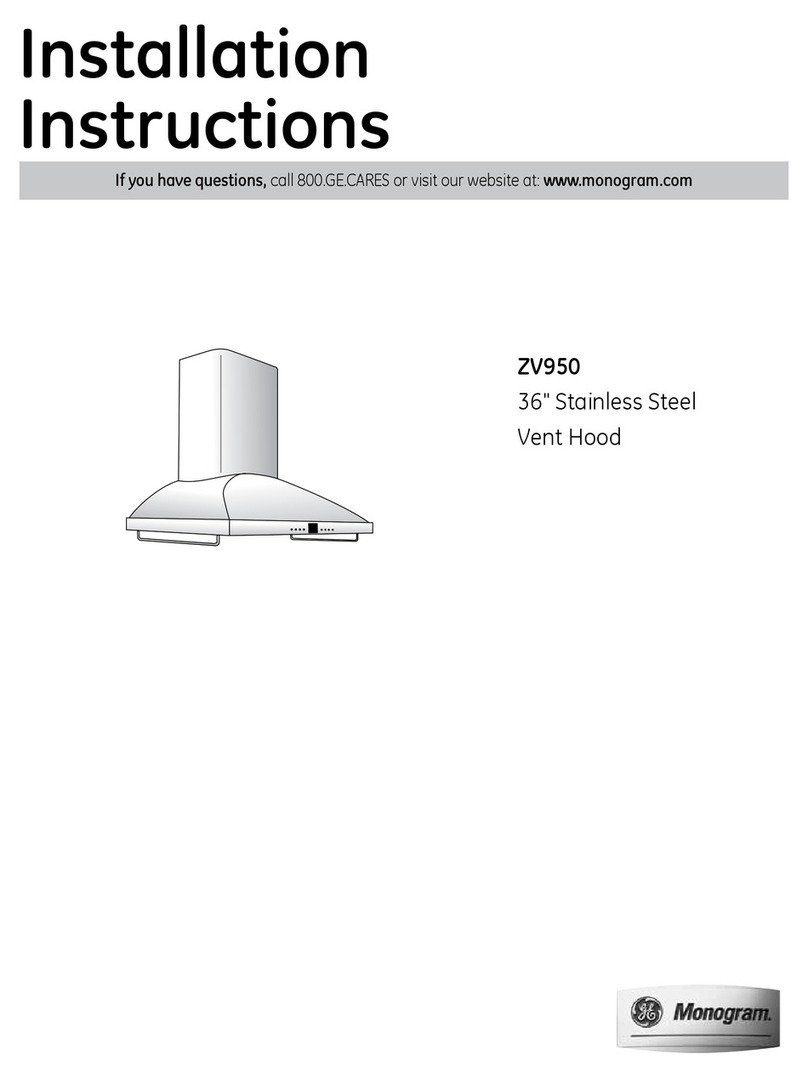
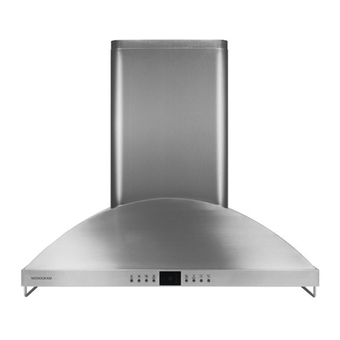
MONOGRAM ZV1050 ISLAND HOOD
IMPORTANT SAFETY NOTICE
THIS INFORMATION IS INTENDED FOR USE BY PERSONS
POSSESSING ADEQUATE BACKGROUNDS OF ELECTRICAL,
ELECTRONIC AND MECHANICAL EXPERIENCE. ANY ATTEMPT
TO REPAIR A MAJOR APPLIANCE MAY RESULT IN PERSONAL
INJURY AND PROPERTY DAMAGE. THE MANUFACTURER OR
SELLER CANNOT BE RESPONSIBLE FOR THE INTERPRETA-
TION OF THIS INFORMATION, NOR CAN IT ASSUME ANY
LIABILITY IN CONNECTION WITH ITS USE.
DISCONNECT POWER BEFORE SERVICING
IMPORTANT: RECONNECT ALL GROUNDING DEVICES
ALL PARTS OF THIS APPLIANCE CAPABLE OF CONDUCTING
ELECTRICAL CURRENT ARE GROUNDED. IF GROUNDING
WIRES, SCREWS, STRAPS, CLIPS, NUTS, OR WASHERS USED
TO COMPLETE A PATH TO GROUND ARE REMOVED FOR
SERVICE, THEY MUST BE RETURNED TO THEIR ORIGINAL
POSITION AND PROPERLY FASTENED.
GROUNDING SPECIFICATIONS
Ground Path Resistance 0.10 Ohms Max.
Insulation Resistance 250K Ohms Min.
INSTALLATION REQUIREMENTS:
Power Supply
The hood must be connected to a supply circuit of the proper voltage and
frequency as specified on the rating plate. Wire size must conform to the
National Electrical Code or the prevailing local code. The rating plate is
located on the left side and is visible when filter is removed.
WARNING: IMPROPER CONNECTION OF ALUMINUM HOUSE WIRING
TO COPPER LEADS CAN RESULT INASERIOUS PROBLEM. USE ONLY
CONNECTORS DESIGNED FOR JOINING COPPER TOALUMINUMAND
FOLLOW THE MANUFACTURER’S RECOMMENDED PROCEDURE
CLOSELY.
MODEL NUMBER ZV1050
IMPORTANT
SERVICE INFORMATION
DO NOT DISCARD
Pub. No. 31-20787
164D3747P087
360-01
REMOVE FILTERS
For access to lighting and wiring.
Grasp knob and push filter towards
the rear, tilt downwards and remove.
NOTE: Review Operation & Service
Diagnostic Flow Chart before
removing any components.
1) ENTRY/DISPLAY ASSEMBLY
The replacement assembly has a PCB mounted in a plastic enclosure with
(8) push buttons. It consists of the Fan Touch Control, Lamp Touch Control
and the Display PCB.
To access this assembly, remove 2 screws on the inside corners of the
front filter channel panel. Remove 2 access panel screws as shown.
Loosen (do not remove) 3 thumb screws until it does not interfere with
control box removal. Slide the display box out to the left side and uncouple
ribbon cable.
Note: Remove the left front light socket to allow more
clearance for removal and replacement of the display box.
1. Remove the trim ring by turning it counterclockwise.
2. Grasp the bulb on the edges and remove by turning
counterclockwise.
3. Remove 2 screws inside the socket.
TO ACCESS
COMPONENTS:
1. Remove bottom screw on
the left side of the duct
cover. Save screw.
Fan Keypad Operation
1- ON/OFF – Remembers the last
fan speed used
2 - Decreases speed
3 - Increases speed
4 - High speed “Boost”
5 - Delayed shut-off – Choose 5,
10 or 20 minutes by pushing
this button (see item 10).
Hood Light’s Keypad Operation
6 - Light ON/OFF – Remembers
the last light level used
7 - Dims light
8 - Brightens light
Display LEDs
9 - Lights after 30 hours of “ON” time
to remind you to clean the metal
grease filters. The light blinks
until the filters are replaced. Then
the timer resets automatically.
10 - Indicates delayed time setting
11 - Fan operating symbol
OPERATION OF FRONT PANEL CONTROL
PUSHBUTTONS & LED DISPLAY
VENT HOOD SYSTEM
CAUTION: Components on the electronic control are electrically HOT
when voltage is connected to the hood.
Be sure to reconnect ribbon cable before reinstalling the control.
IMPORTANT: Before replacing the assembly, check the operation of the
hood by plugging the new Entry/Display Assembly into the existing ribbon
cable. If the unit does not work, replace the control board first and recheck
to determine if the existing Entry/Display Assembly is functioning properly.
2) DISPLAY CRYSTAL – To access display crystal, follow step 1.
3) CONTROL PCB – This PCB has theAC to DC power supply, micropro-
cessor and fan relays and is located in
the left blackbox in the hood chimney
area.
NOTE: The five green connectors are
locking type. Use a small flat-blade
screwdriver to unlock as follows:
Insert screwdriver in
the center of the space
between the plug and connector
receptacle on the PCB. Push
down on the screwdriver and
pull out the plug at the same
time.
TO CHECK OPERATION OF CONTROL PCB: Check that all six connec-
tors are locked in place, no leads are broken and connector solder joints
are not broken on PCB copper side.
4) TRIAC – The triac controls and the four hood lamps are mounted in a
blackbox in the right chimney area. Triac has an isolated case, which is
mounted with two screws.
IMPORTANT: Triac wire connection
must be correct or lamp flickering
could occur.
Triac can be checked for
electrical short by
removing the black
lead and measuring
the resistance between
the two 1/4" terminals
(terminals with
black and
brown wires).
Resistance
should be
greater than
1M ohm.
5) FUSE HOLDERS
The fuse holders are an in-line type, which is in series with 12V AC from
the transformer and is located in the right blackbox. An open fuse may be
caused by a lamp failing or wrong wattage lamp.
NOTE: The fuses are 5 x 20 mm and rated at (5) A, 125V AC.
(WB27X10542).
6) MOTOR CAPACITORS
The capacitors are mounted on left chimney and plugs into the Control
PCB connector CN3.
7) INDUCTION FAN MOTOR ASSEMBLY
Motors are four speed capacitor run induction types, each rated at
120V AC/6.6A.
05
10
20
1234 5678
91011
Motor Capacitor
Left Blackbox
Fuse Holders
Right Blackbox
Brown
Black
Orange
Triac
Motor Connection
Terminal Box
Reinstall
Attachment
Screw
MOTOR ASSEMBLY
• Remove motor leads from connector in right blackbox and loosen strain
relief
• Remove (4) screws from beneath the chassis
• Lower motor down (recommend (2) person job)
Motor stator winding resistances:
Orange-Red = 4 ohms Blue-Black = 6.6 ohms Blue-White = 3.3 ohms
Motor connections are located in the right blackbox.
8) TRANSFORMER
The transformer provides 12V AC to the hood lamps and the Control PCB
power supply. It is attached by screws from the top right of the chassis.
9) HALOGEN LAMPS
The four halogen lamps are the push-in type rated at 12V AC/20W. The
equivalent GE lamp is a Q20MR16/C/CG40 - BAB (W808X10002).
10) FILTER MICROSWITCH (Located in front right filter channel)
Microswitch is mounted in the filter area and senses when filters are
removed which causes the red display light to blink continually. The red
display light turns “ON” after 30 hours of fan operation to remind the user
to clean the filters. Make sure the filter is seated properly when installed or
filter light will blink.
11) IMPLEMENT HOLDER RODS
Remove filters for access to screws holding rods under chassis.
Screws (2) holding the implement holders can now be removed from
the inside.
2. Slide bottom duct
cover up. Locate
service manual
envelope with stop screw.
3. Install stop screw as shown in the bottom hole of the inner duct cover.
Stop
Screw
Bottom
Duct Cover
Slide Bottom
Duct Cover Up
Install Stop
Screw in Hole
of Upper (Inner)
Duct Cover
REINSTALL DUCT COVERS
• Remove stop screw and place
in envelope
• Slide duct cover down
• Reinstall attachment screw
Blower Mounting Screws
Remove
Attachment
Screw
Entry Display
Control PCB Box Fuse
Holders
Motor
Capacitor
(2) Implement Holder Rods
Display Crystal
Filter Microswitch
Induction
Fan Motor
Triac
HVT
Uncouple
Ribbon Cable
Remove
Left Socket
Remove
Access Panel
Remove Filter
Channel Panel Front
Remove
Screw Remove
Screw
