49-80329 Rev. 5 3
Design Information
CONTENTS
Design Information
ProductDimensions ...................................................... 3
Advance Planning
AdvancePlanning ........................................................ 4
PowerSupply ............................................................... 4
DuctFittings ................................................................ 5
Installation Preparation
Tools and Materials Required ....................................... 6
RemovethePackaging ................................................ 6
Installation Height ......................................................... 7
PartsProvided.............................................................. 8
Installation Preparation
Construct Ceiling Support ............................................. 9
Installation Instructions—Vented to the Outside
Step1,MountTemplate.............................................. 12
Step2,AdjustFrameHeight ....................................... 12
Step3,CutDucttoLengthforVentedInstallation...... 13
Step4,InstalltheSupportFrame ............................... 13
Step5,InstallHoodAttachmentScrews..................... 13
Step6,MounttheHoodontotheSupport .................. 14
Step7,ConnectCables .............................................. 14
Step8,ConnectElectrical........................................... 15
Step9,PreparetheDuctCovers ................................ 16
Step10,InstallUpperDuctCover .............................. 16
Step11,InstallLowerDuctCover .............................. 17
Step12,InstallDuctCoverTrim ................................. 17
Step13,InstallMetalFilter.......................................... 17
Step14,FinalizeInstallation ....................................... 17
Installation Instructions—Recirculating
Step1,MountTemplate.............................................. 18
Step2,AdjustFrameHeight ....................................... 18
Step3,InstallAirDeflector,CutDuct
for Recirculating Operation............................. 19
Step4,InstallUpperSupportFrame .......................... 19
Step5,InstallLowerStructuretoUpperStructure ..... 20
Step6,InstallBlower/Motor ........................................ 20
Step7,InstallHoodAttachmentScrews..................... 20
Step8,MounttheHoodontotheSupport .................. 20
Step9,ConnectCables .............................................. 21
Step10,ConnectElectrical......................................... 21
Step11,PreparetheDuctCovers .............................. 22
Step12,InstallUpperDuctCover .............................. 22
Step13,InstallLowerDuctCover .............................. 22
Step14,InstallDuctCoverTrim ................................. 23
Step15,InstallFilters.................................................. 23
Step16,FinalizeInstallation ....................................... 23
PRODUCT DIMENSIONS
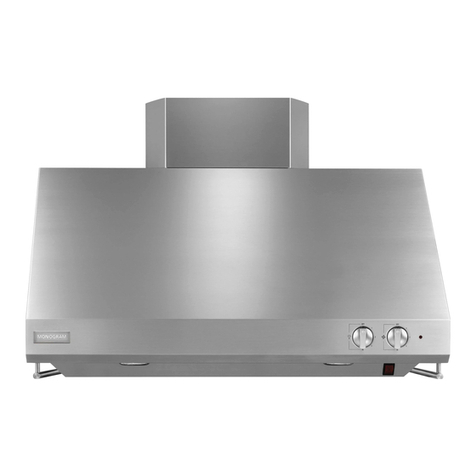
These vent hoods are supplied with a support frame for
ceilingheightsof7’-11”to10’-1”.
Decorative duct covers conceal the ductwork running
from the top of the hood to the ceiling.
ZX92510accessoryisavailableforceilingheightsof
9’-1”to10’-1”.
NOTE: Installation height should be measured from the
cooking surface to the bottom of the outer glass portion
of the hood.
Thishoodmustbeinstalled24”min.and30”max.
above the cooking surface. The cooking surface should
beatleast36”abovethefloor.
Thishoodmaybeventedtotheoutdoors,oritcanbe
installed for recirculating operation.
This hood can be installed over any Monogram electric
or gas cooktop. It cannot be installed over a Monogram
Professionalcooktoporrange.
* Thesuppliedductcoverfits7’-11”to9’ceilingheights.
For9’-1”to10’-1”ceilings,orderZX92510.
16"
3 1/4"
35 7/8"
*Height
to
Ceiling
2 3/4"
*Height to
ceiling
279/16" 357/8"
24" min.*
30"max.*
36" min.
*Exactinstallation
height depends on
ceiling height.
1”=2.5cm;1’=0.3m

