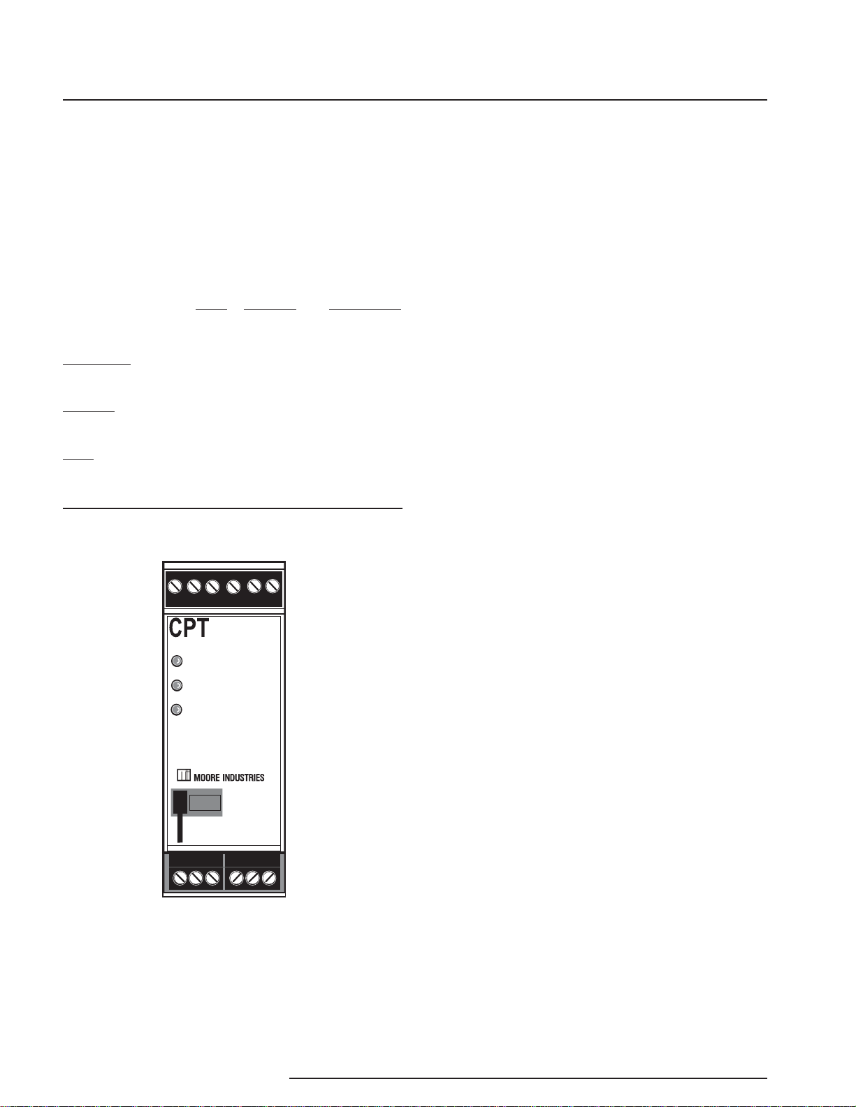
CPT
10 The Interface Solution Experts
PC-Programmable Signal
Isolater/Converter
10. Alarm Parameters– Use this to choose an alarm
mode and configure as either a Trip, Fault or Band
alarm. Select whether to use as a Fail Safe or NON
Fail Safe Alarm. You may also choose a Delay (0-
120sec) and a Deadband (0-100%). Refer to the
Alarms section for a complete description.
11. Trimming/DampingTab– Selecting this
parameter allows you to perform Sensor Trim, Output
Trim and Output Damping functions. Refer to the
Trimming/Damping section for a complete description.
12. CustomTableTab– The CPT has two modes of
operation: linear mode and custom mode. In linear
mode, the scaled output is proportional to the scaled
input. In custom mode, reached by selecting the
Custom Table Tab, you define a special linearization
function. Refer to the Custom Table section for a
complete description.
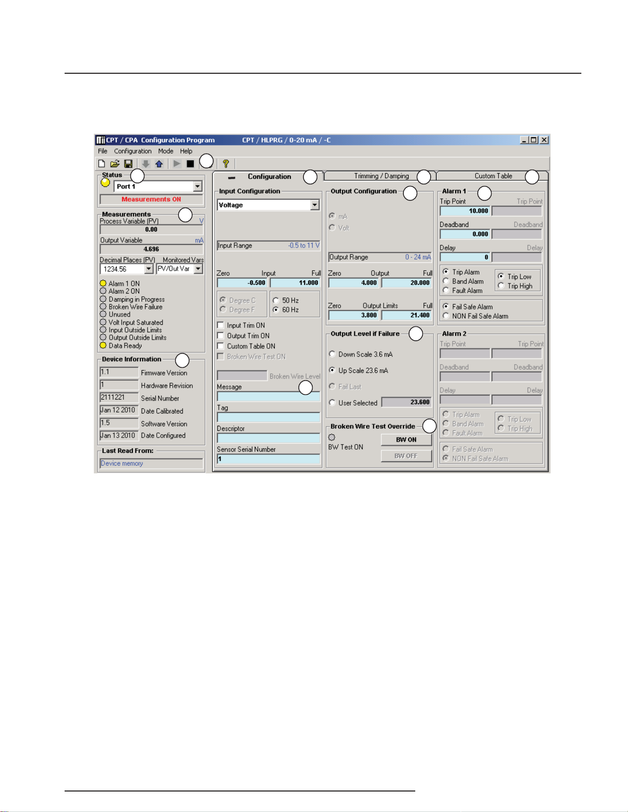
Configuration
Output Level if Failure
In the Output Level if Failure section you will notice
Down Scale and Up Scale selection. Using its output,
the CPA can be configured to provide a special
warning of a breakdown or failure. Use this setting to
configure the instrument to drive its output either up or
down when a failure is detected. For current outputs,
limits are 3.6mA (downscale) and 23.6mA (upscale);
for voltage outputs, limits are -0.5V (downscale) and
11.0V (upscale).
When a failure is detected, the “Fail Last” feature, if
enabled, holds the last measured value before the
failure occurred.
If the “User Selected” feature is enabled, you may
enter any value, within the range, to view at the output
when a failure is detected.
Broken Wire Test Override
The CPT monitors your primary variable.If the
monitored value falls equal to or below a set value,
then a state of Broken Wire is declared.
Select the value of the primary variable which will
be considered “failure” and place it in the “Broken
Wire Level” text box.The range of this value must be
higher than zero (0.00mA or 0.00V) and less than the
“Zero Input Range”. Normally, a value of 0.1 or 0.2 is
sufficient.
When a failure is detected, “Broken Wire Failure” in the
Process Information section will light along with the
associated “Broken Wire” light(s) to indicate a problem.
If you are using theTrip or Band Alarm function, your
alarm status will remain unchanged as a result of
the failure. If the Fault Alarm is enabled, the alarm
is activated and resets once the failure has been
corrected.
In order to activate Broken Wire detection, you must
check the “BW ON” box and enter your selected
“failure” value.
Note:
Once you have configured all parameters,
download to the unit by either selecting “Download
Configuration” in the Configuration dropdown menu
located in the Communications bar or by clicking the
button.