SDY
6 The Interface Solution Experts
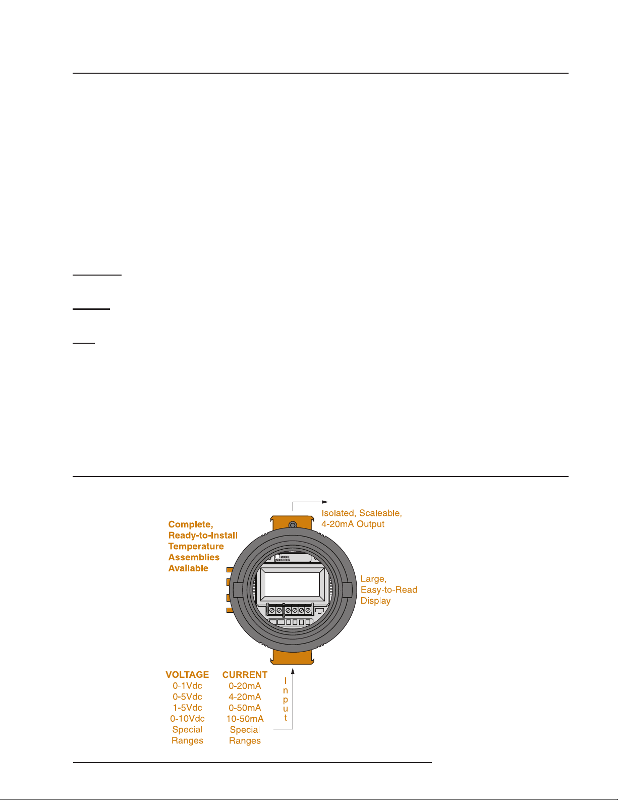
PC-Programmable Signal
Isolator/Converter with Display
Installing the
Conguration Software
Refer to Table 1 for the equipment needed.
1. Insert the Moore Industries Interface
Solution PC Conguration Software CD
into the CD drive of the PC. Access the
CD and open the SDY SIY TDY TRX
TRY 64 bit PC Conguration software
folder.
2. Double-click the installation program
located in the folder. Follow the
prompts to correctly install the program.
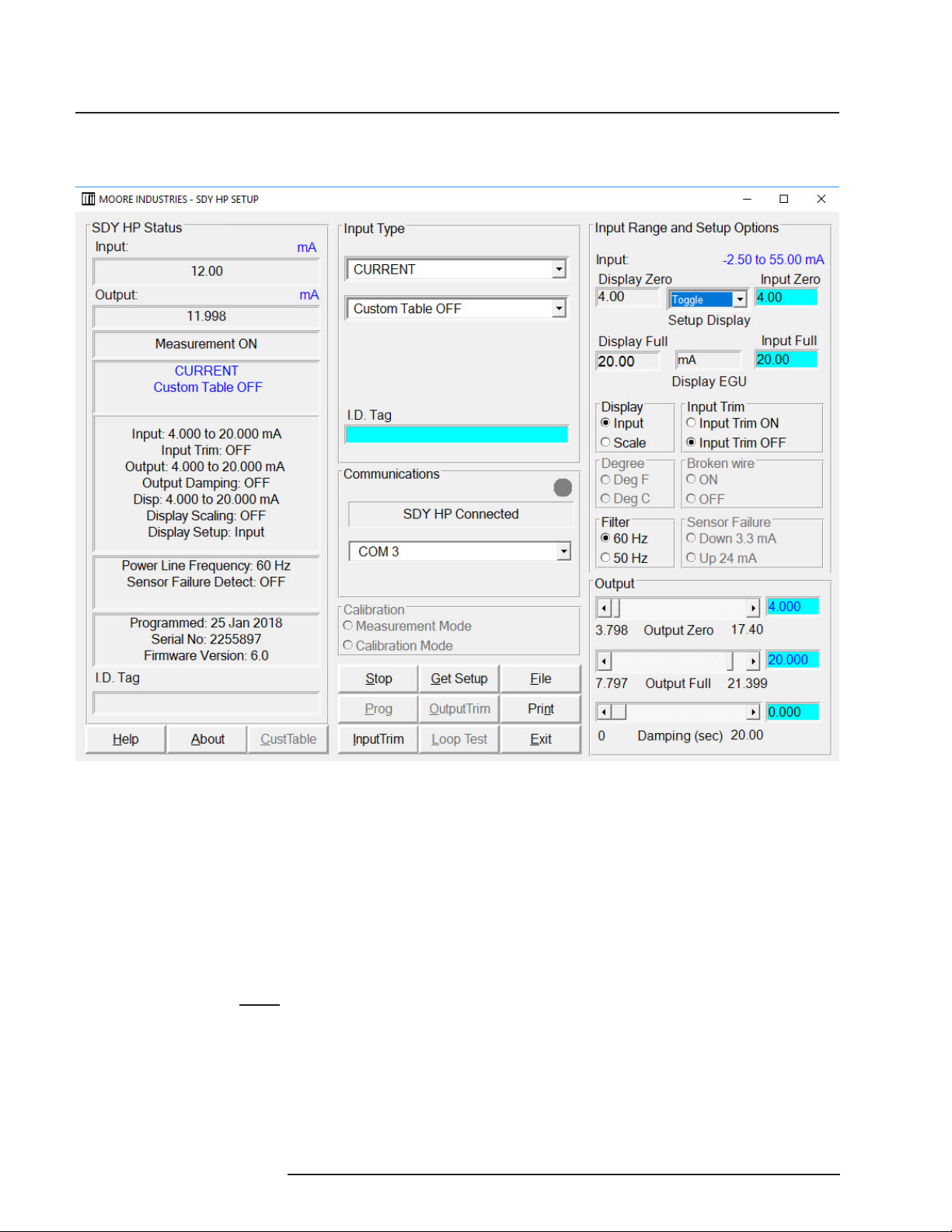
Once the Conguration Program is installed on the
PC, the SDY can be connected to equipment to
simulate input and monitor output. You can then
change the transmitter’s operating parameter
CAUTION:
Any time a connected SDY is “programmed”
by downloading a Conguration File into memory,
ALL of the conguration parameters resident
in the transmitter memory at the time of the
download are OVERWRITTEN. This includes
things like: tag name, calibration date, trim values,
etc.
Conguration
Conguring the SDY consists of:
1. Checking to verify that the unit ordered is in fact
the one received and that it has been correctly
calibrated by the factory according to the order.
2. Installing the SDY Conguration Software by
following the directions on the label.
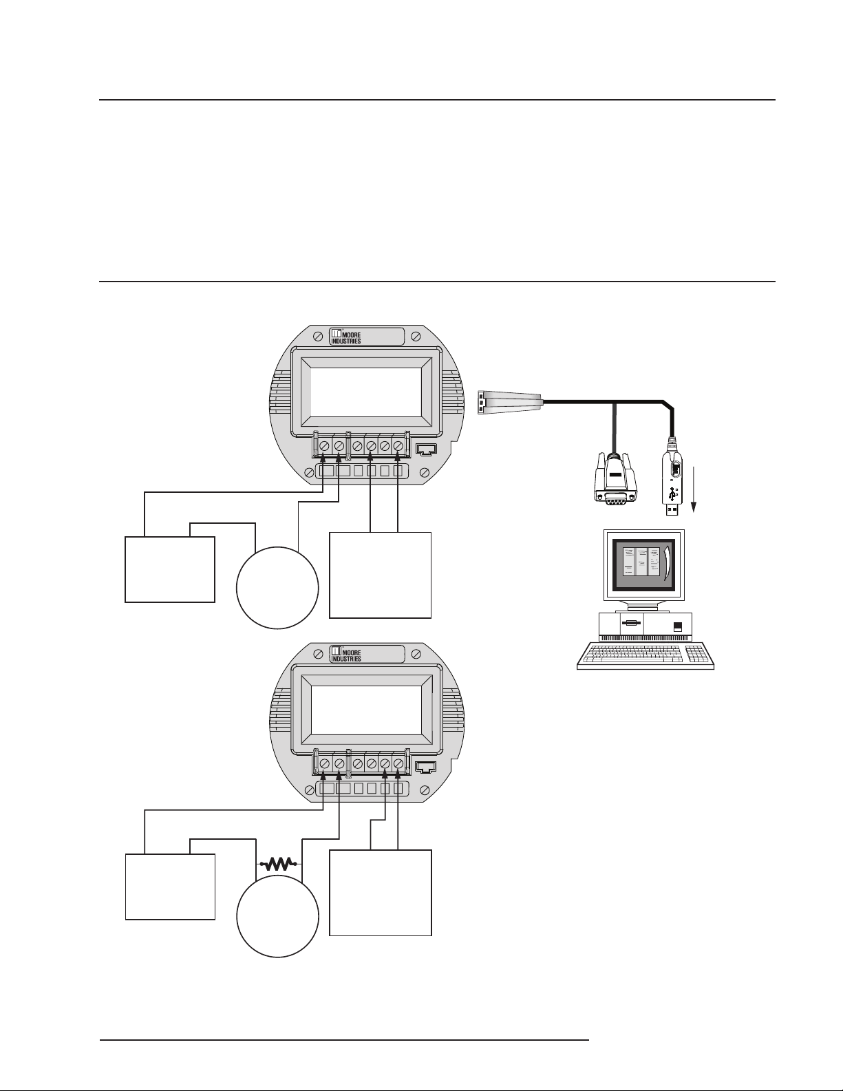
3. Connecting the SDY to a PC and test setup,
running the SDY PC Conguration Program to
check for correct unit tagging, input type and
range settings, and output zero/span trim.
Prior to shipment, our team of skilled technicians
subjects every SDY to rigorous testing. Every
product Moore Industries manufactures, sells, and
services is guaranteed to meet the strict quality
standards that our company demands.
Even if a unit has been congured to your
specications by the factory (factory calibration),
it is a good idea to perform a bench check. In
addition to providing a safe means of uncovering
any unit damage that may have occurred during
shipping, the procedures aord the user the
opportunity of becoming familiar with SDY operation
in a testing environment that is separate from the
intended process or application.
Note:
The procedures in this section should be carried
out in an environment considered appropriate for
the general testing of electronic equipment, rather
than in the eld. Use a technician’s bench or
similar, lab-type environment.
Specication
Accurate to ±0.05% of span for
the intended application
18-42Vdc, ±10% (10-42VDC if
no load resistor is used)
250Ω, ±0.01%
Accurate to ±0.025%
Device
Current or
Voltage Source
Power Supply
Precision Load Resistor
(optional)
Multimeter
Personal
Computer
Moore Industries’
Communication Cable
Table 1. SDY Conguration Equipment
Microsoft Windows based PC;
16Mb free RAM; 20MB free disk
space on hard drive
Microsoft Windows XP, Vista or
7 and 1 (one) serial port or one
available USB port (with optional
USB cable)
Non- isolating (PN 803-040-26)
Isolating (PN 803-039-26)
Fuse Protected USB Cable (PN
804-030-26)