Moore Industries SIX User manual

SIX
Signal Isolator/Converter
USER’S MANUAL
May 2016 No. 297-701-00 C
© 1991 by Moore Industries-International, Inc.

Moore Industries’ STAR Center has a
wide variety of quality instrumentation
in stock and ready to ship.
• Signal Transmitters
• Temperature Transmitters
• P/I and I/P Converters
• Isolators and Converters
• Indicators and Displays
• Alarm Trips
• Integrators and Totalizers
• Power Transducers
• Instrument Power Supplies
• Racks, Rails and Enclosures
Most instruments can be customized
to meet your needs. Even then, you’ll
never have to wait more than a few days.
*Support, Technical Assistance, and Repair (our Quick-Ship Facility)
Moore Industries
CENTER
United States/Canada
TOLL FREE
1-800-999-2900
United Kingdom
FREE PHONE
0800 525107
Australia
TOLL FREE
008 251928
16650 Schoenborn Street
Sepulveda, California 91343, U.S.A.
Tel: (818) 894-7111 • Tlx: 65-1322
FAX: (818) 891-3297
CONNECT (MacNet): MIISEPULVEDA
3/18 Resolution Drive, Caringbah
New South Wales 2229, Australia
Tel: (02) 525-9177 • Tlx: 790-75914
FAX: (02) 525-7296
1 Lloyds Court, Manor Royal, Crawley
W. Sussex RH10-2QU, United Kingdom
Tel: 0293 514488 • Tlx: 87667
FAX: 0293 536852
Ask for the STAR Center
*
48
HR.
Table of Contents
Introduction 1
Description 1
Calibration 1
Installation 5
Operation 7
Maintenance 7
Troubleshooting 7
DELIVERY

SIX
Page 1
Introduction
Moore Industries’ Signal Isolator/Converter (SIX) is a
DIN-style, loop-powered device, used to provide
complete isolation of instrumentation input and
output. This helps eliminate faulty readings in
measurement and control equipment caused by
ground loops, electrical interference, or motor noise.
This manual provides a brief description of the SIX, a
list of performance and functional specifications, a
calibration procedure, operations notes, and trouble-
shooting information.
Notes and Cautions, where they appear in text or
illustrations, are provided to assist the user in
avoiding operational inconveniences (Notes), or
practices that otherwise might result in damage to
the unit (Cautions).
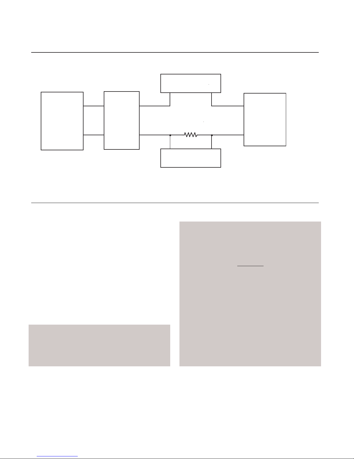
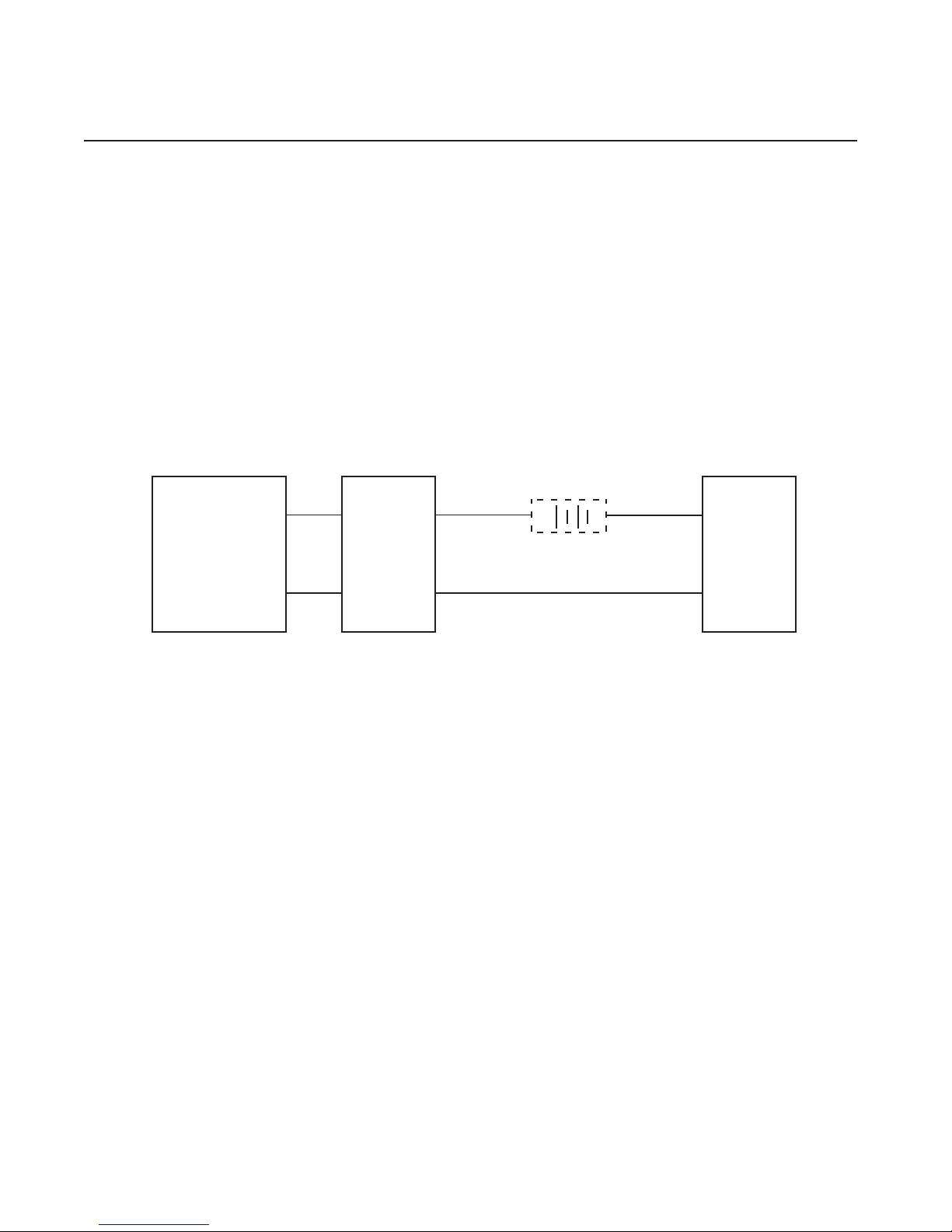
Description
The SIX is loop-powered. When connected in a 12-
42 Vdc loop, it converts a standard process current
or voltage signal to a proportional, isolated 4-20 or
10-50 mA output; breaking the galvanic path be-
tween a transmitted signal source and its receiving
device.
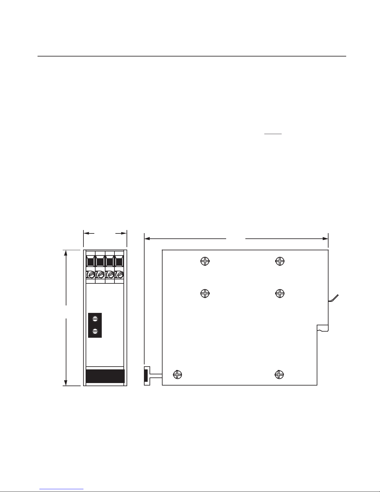
The unit is packaged in a compact, DIN-style hous-
ing that snaps easily on to G-rail mounting hardware
(DIN EN50035). This makes it ideal for use in high
density installations.
Controls
The SIX has Zero and Span potentiometers located
on the front panel of the unit. On older units these
were labeled:
for Zero, and
for Span.
On newer the words “ZERO” and “SPAN” may be
used to identify the potentiometers.
Table 1 consists of the SIX performance and func-
tional specifications.
Options
Units may be ordered with RFI-filtered terminals and
case assembly (RF Option). RF-equipped units
provide RFI/EMI protection up to 50V/M - abc =
±0.1% F.S., as defined by SAMA standard 33.1.
Contact your Sales Representative or Moore Indus-
tries for more information on available SIX options
and compatible devices.
Serial Number. A complete history of every unit
sold and serviced by Moore Industries is kept at the
factory. This data is keyed to each unit’s serial
number. If service data is required on an SIX,
providing the factory with the unit serial number will
allow our highly skilled technicians to better assist
you.
The SIX serial number is located on a label affixed to
the side panel of the unit.
Model Number. Moore Industries' model numbers
identify the type of instrument, functional character-
istics, operating parameters, any options ordered,
and housing type. If all accompanying documenta-
tion for a unit is missing, the model number may be
used to obtain technical information.
The model number for the SIX is located on the
same label as its serial number.
The example following Table 1 is provided to assist
in deciphering the fields of the SIX model number.
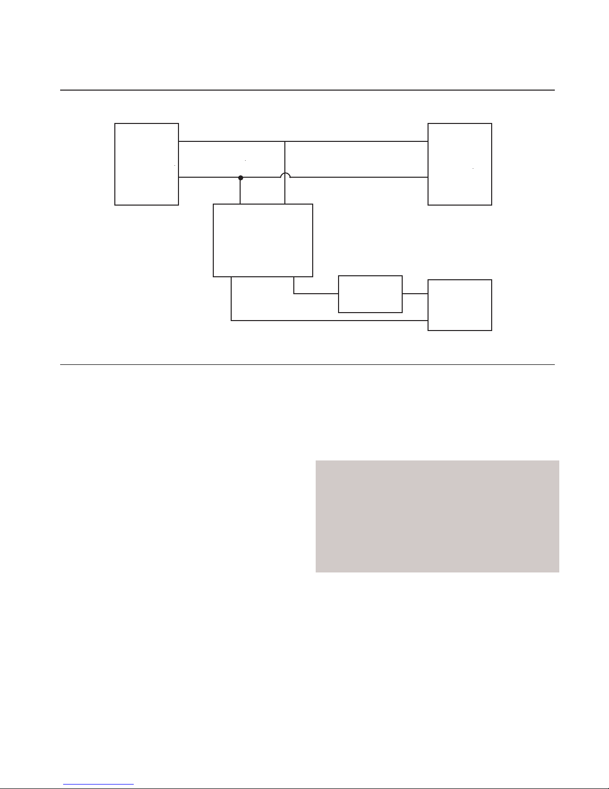
Calibration
Prior to unit shipment, each SIX is calibrated and
tested according to Moore Industries’ strict quality
control guidelines. It is recommended, however, that
a bench check of potentiometer settings and output
levels be performed before placing the SIX into
service.

SIX
Page 2
Table 1. SIX Specifications
Characteristics
Input
Output
Power
Performance
Adjustability
Environmental
Ratings
Weight
Specifications
Factory-set. Available ranges are:
0 to 20 mA
4 to 20 mA
–1 to +1 mA
0 to 10 V
1 to 5 V
0 to 1 V
Factory-set. 4 to 20, or 10 to 50 mA.
2-wire loop-power; 12 to 42 Vdc.
Isolation: Input and output are transformer-isolated with no galvanic path (dc connection)
up to 500 Vrms.
Frequency Response: 10 Hz at the 3 dB point.
Maximum Input Over-range: ±60 V
Input Impedance: 1.0 Mohm for voltage inputs; 50ohms for 4-20 mA input;
1 kohm for –1 to +1 mA input.
Load Capability: 4-20 mA into 1500ohms; limited to 50 mA, maximum.
Power Supply Effect: Less than 0.05% of span over the full power supply range.
Calibration Accuracy: ±0.1% of span.
Zero potentiometer adjusts unit zero to within ±5% of span.
Span potentiometer allows for 100% adjustment, ±10%, with full-scale input.
RFI/EMI Effect: Without RF Option, effect is negligible @ 25 V/m at typical communica-
tions frequencies. With RF, protection of 50 V/m-abc = ±0.1% F.S., as defined by SAMA
Standard 33.1.
Ambient Operating Temperature Range: –30 to +82 °C (–22 to +180 °F).
Temperature Change Effect on Unit Operation: 0.015% of span per °C change over a
0 to 70 °C range.
Approximately 215 grams (7.6 ounces).
NOTE: Refer to Installation Section of this manual for unit dimensions.
Calibration Equipment
Table 2 lists the calibration equipment required for this
bench check procedure. This equipment is not
supplied with the unit.
Calibration Setup
Figure 1 shows the calibration setup for the SIX. To
check or calibrate the SIX, connect the unit as shown
in the illustration, and apply the power according
specification (refer to the specifications table and the
model number of your unit).

SIX
Page 3
Table 2. SIX Calibration Equipment
EXAMPLE
SIX / 4-20mA / 10-50mA / 12-42DC / -RF [DIN
]
Unit Type
Inpu
t
Output
Powe
r
Housing
Option
s
Equipment Characteristics
Signal Source Appropriate for the intended SIX application, accurate to within ±0.05% of span, minimum
DC milliammeter Fluke model 8899, or equivalent unit accurate to within ±0.05% of span, minimum.
or
DC voltmeter with
Precision resistor
Voltmeter accurate to within ±0.05% of span, minimum.
Power Supply Capable of 12 to 42 Vdc.
Screwdriver Slotted head, width 2.54 mm (0.1 inch).
Resistor: 250ohm (±0.1%), rated for 4-20 mA.

SIX
Page 4
Figure 1. SIX Calibration Setup
Note that there are no internal adjustments or settings
to effect on the SIX. Disassembly of any kind is not
recommended.
After applying power, allow approximately five min-
utes for stabilization/warm-up.
Calibration Procedures
There are two options for monitoring the output of the
SIX shown in the figures; either a dc milliammeter or
a dc voltmeter with load resistor may be used to
monitor and set output levels.
1. With the calibration setup complete, adjust both
potentiometers 15 turns counterclockwise, then
7.5 turns clockwise (mid-scale).
2. Simulate zero percent input.
3. Adjust zero potentiometer until milliammeter
reads 4 mA for 4-20 mA units, 10 mA for
10-50 mA units, or until voltmeter reads 1 volt.
CAUTION
To avoid damaging the housings, use a
screwdriver with a head not wider than
2.54 mm (0.1 inch) to adjust the zero and
span potentiometers.
4. Set input to 100 percent.
5. Adjust span potentiometer until milliammeter
reads 20 mA for 4-20 mA units, 50 mA for
10-50 mA units, or until voltmeter reads 5 volts.
6. Repeat steps 2 through 5 until zero and 100
percent readings are stable, ±0.1%.
MILLIAMMETER
VOLTMETER
+ PS
–
PS
+
IN
–
IN
SIGNAL
SOURCE
SIX
NOTE: Either milliammeter or voltmeter may be used for monitoring output.
–
(SEE NOTE
)
12-42 Vdc
POWER
SOUCE
–
–
+
–
+
+
+

SIX
Page 5
Installation
In this manual, the installation of the SIX is divided
into two phases: physically mounting the unit, and
making the electrical connections. It is recom-
mended that the unit(s) be mounted before making
any connections.
Mounting
When mounting the SIX, make every effort to install it
in an area that is relatively free of dust, moisture, and
corrosive materials.
Figure 2 shows the mounting dimensions for the SIX.
To mount the unit on a DIN-style G-rail, insert the
metal clip on the unit’s back panel under the top lip of
the rail. Pivoting on the clip, press down firmly until
the SIX snaps into place.
If it becomes necessary to remove the unit, grasp the
bottom of its front panel and lift upward.
NOTE
The SIX has no case ground connection.
If possible, avoid mounting the unit in any
electrical field. Secure the case to a
good conductor at zero potential.
Figure 2. SIX Outline Dimensions
80 mm
(3.15 in)
25.40 m
m
(1.0 in)
ZERO
SPAN
SIX
SIGNAL
ISOLATOR
119 mm
(4.67 in)
+IN -IN +PS -PS

SIX
Page 6
Electrical Connections
The SIX has four terminals on its front panel. They
are labeled “+IN” and “–IN” for connection of the
signal input, and “+PS” and “–PS” for connection of
the unit’s output.
Figure 3 illustrates the connection of the SIX in a
generic application.
Figure 4 shows the unit connected in another typical
operational scenario.
To complete these connections, use a small, slotted
screwdriver to loosen the SIX terminal screws, and
slip the appropriate stripped wire end into the terminal
hole. Tighten the terminal screw.
Both the input and output may be grounded. The SIX
input and output are transformer-isolated with no dc
connection between them. This isolation provides 67
dB common mode rejection, and allows the input to
float with respect to the output.
Figure 3. SIX Typical Installation Hookup
12-42 Vdc
POWER SOURCE
RECEIVER
–
+
+ IN + PS
– IN – PS
FIELD SERVICE
(NON-ISOLATED
TRANSMITTER)
SIX
+–
(ISOLATED 4-20 or 10-50 mA SIGNAL)

SIX
Page 7
Operation
Once mounted and connected according to the
instructions, the SIX operates unattended. After the
initial calibration of the Zero and Span potentio-
meters, no further adjustment is required.
Maintenance
A check of terminal connections is recommended
every six months. Ensure that all terminal screws are
tight and free of corrosion. Check that adequate
ventilation exists, or that heat sinking materials are
used in mounting.
Troubleshooting
If the SIX is found to be performing below specifica-
tion, complete the following checklist:
1. Make sure all connections are clean and tight.
2. Verify the accuracy and calibration of bench
instruments used to take measurements.
3. Ensure that signal and power levels in the
instrumentation loop have not changed since the
unit was installed. Make sure that power is
within specified limits (refer to table 1).
If problems persist, note the serial and model num-
bers of the offending unit, and contact Moore Indus-
tries’ Customer Service Department. Instructions for
return of Moore Industries equipment are on the back
cover of this manual.
Figure 4. SIX Installed as a Repeater/Diverter
TRANSMITTER
–IN +IN
–PS +PS
SIX
DCS
POWER
RECORDER
+
–
+
–
1-5 Vdc
–+
Other manuals for SIX
1
Table of contents
Other Moore Industries Media Converter manuals
Popular Media Converter manuals by other brands

DMX
DMX soundlight 7044B-H operating manual

Sharp
Sharp DK-AP8P Operation manual

TRENDnet
TRENDnet TFC-1000MGB - Intelligent 1000Mbps TX Specifications

McIntosh
McIntosh MDA1000 owner's manual

Omnitron Systems Technology
Omnitron Systems Technology iConverter 100Tx user manual

Esu
Esu LokSound micro V4.0 instruction manual