TYCROP Manufacturing Ltd. QuickPass Top Dresser Setup Manual
Table of Contents Page iii
Table of Contents
Setup Instructions.............................................................................................................1
How to Set Up the Chassis........................................................................................1
QP300 Only......................................................................................................2
QP450 Only......................................................................................................2
How to Install the Honda Engine ...............................................................................2
How to Install the Tow Vehicle Hydraulic Option.......................................................5
How to Install the 2 Way Switch Option.....................................................................8
How to Install the QuickPass 300 Red Hopper .......................................................12
How to Install the QuickPass 450 Yellow Hopper ...................................................13
How to Install the Hopper Insert ..............................................................................15
Maintenance Instructions ...............................................................................................18
How to Change the Belt Assembly ..........................................................................18
How to Change Tires ...............................................................................................21
How to Change an Outside Tire.....................................................................21
How to Change an Inside Tire .......................................................................21
How to Upgrade the Honda Engine Fuel Tank to the TyCrop 9L Fuel Tank...........21
How to Remove the Old Tank........................................................................21
How to Install the New Tank ..........................................................................22
Figures
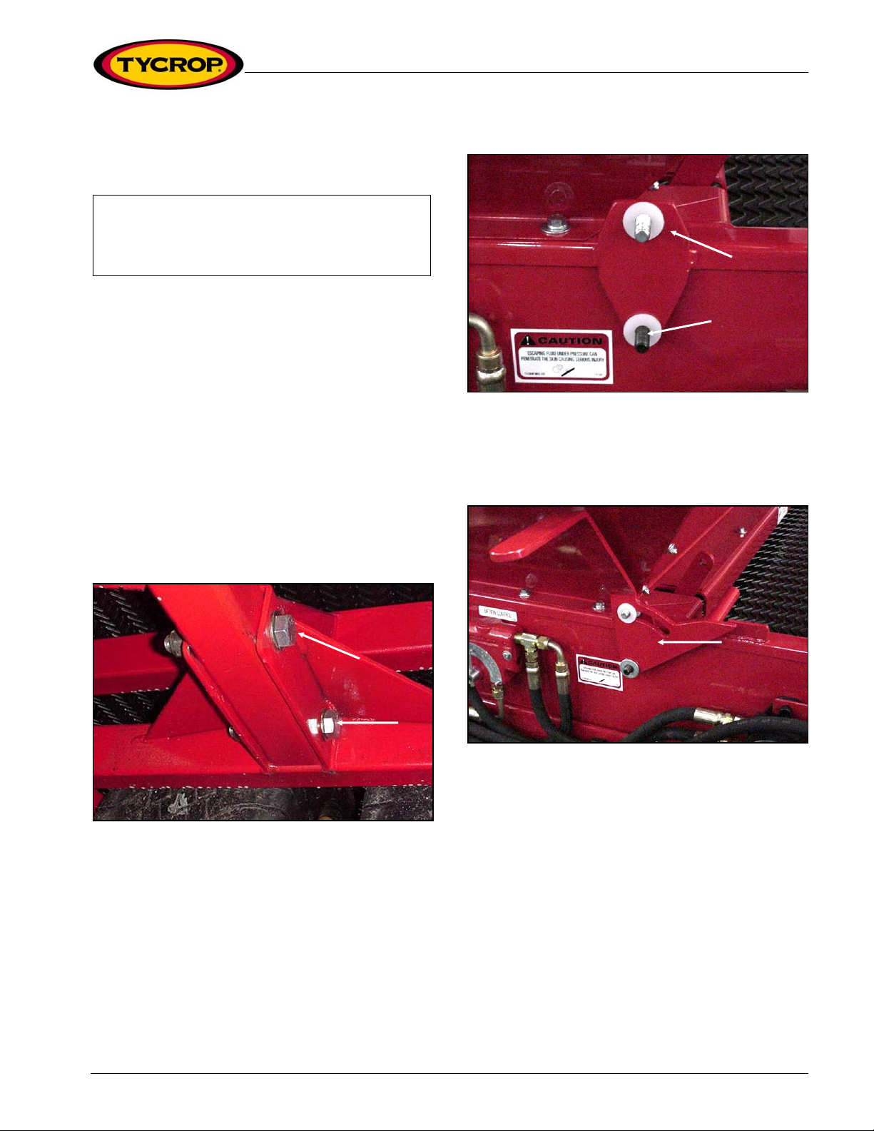
Figure 1: Tighten nylon locking nuts to hitch tube .....................................................1
Figure 2: Install plastic washers over welded bolts ...................................................1
Figure 3: Install flat washers over welded bolts.........................................................1
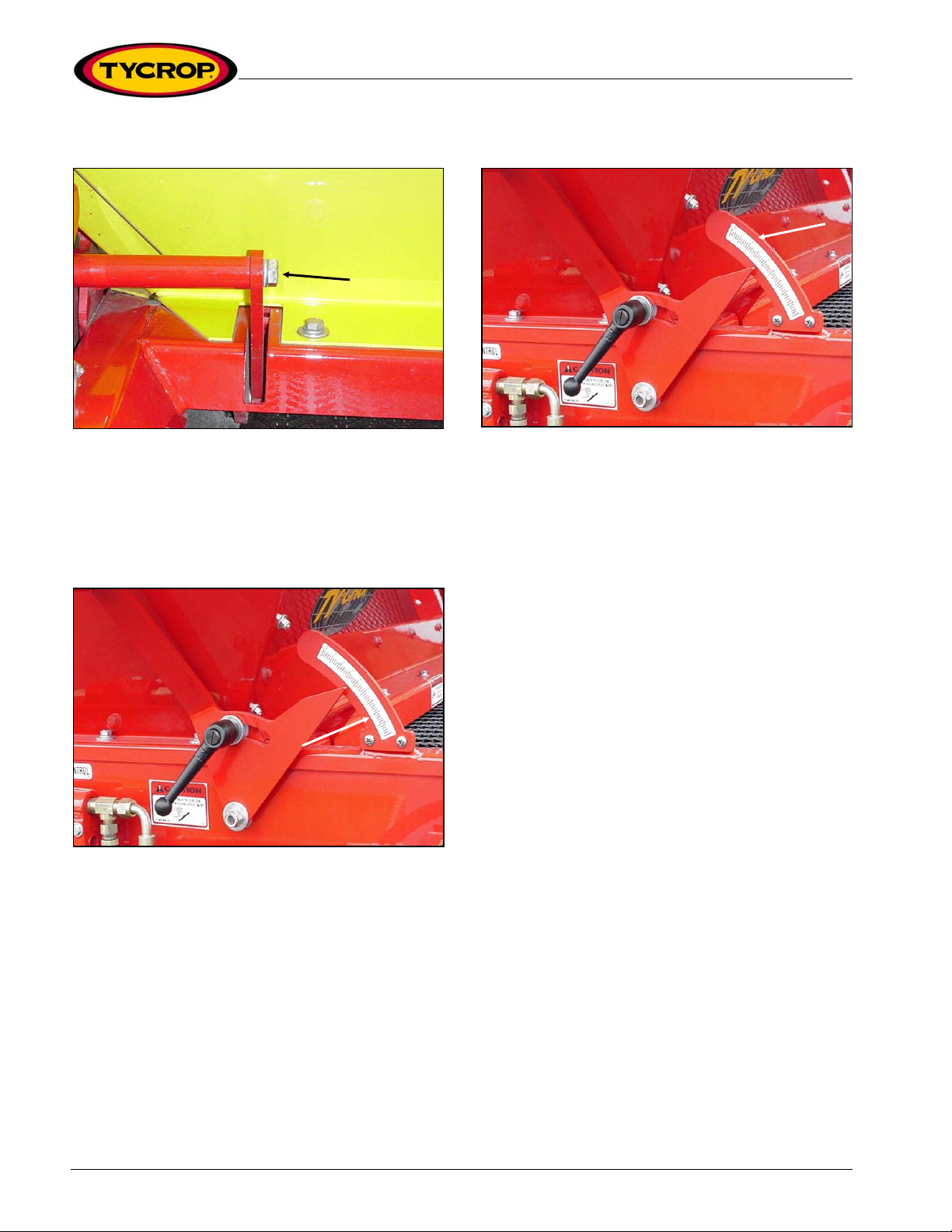
Figure 4: Install bolt and lock washer through gate-adjusting arm ............................2
Figure 5: Place the gate metering bar .......................................................................2
Figure 6: Install metering bar sticker..........................................................................2
Figure 7: Decal Placement ........................................................................................3
Figure 8: Remove battery plugs.................................................................................3
Figure 9: Connect hydraulic hoses to fittings.............................................................3
Figure 10: Connect hydraulic hoses to ports .............................................................4
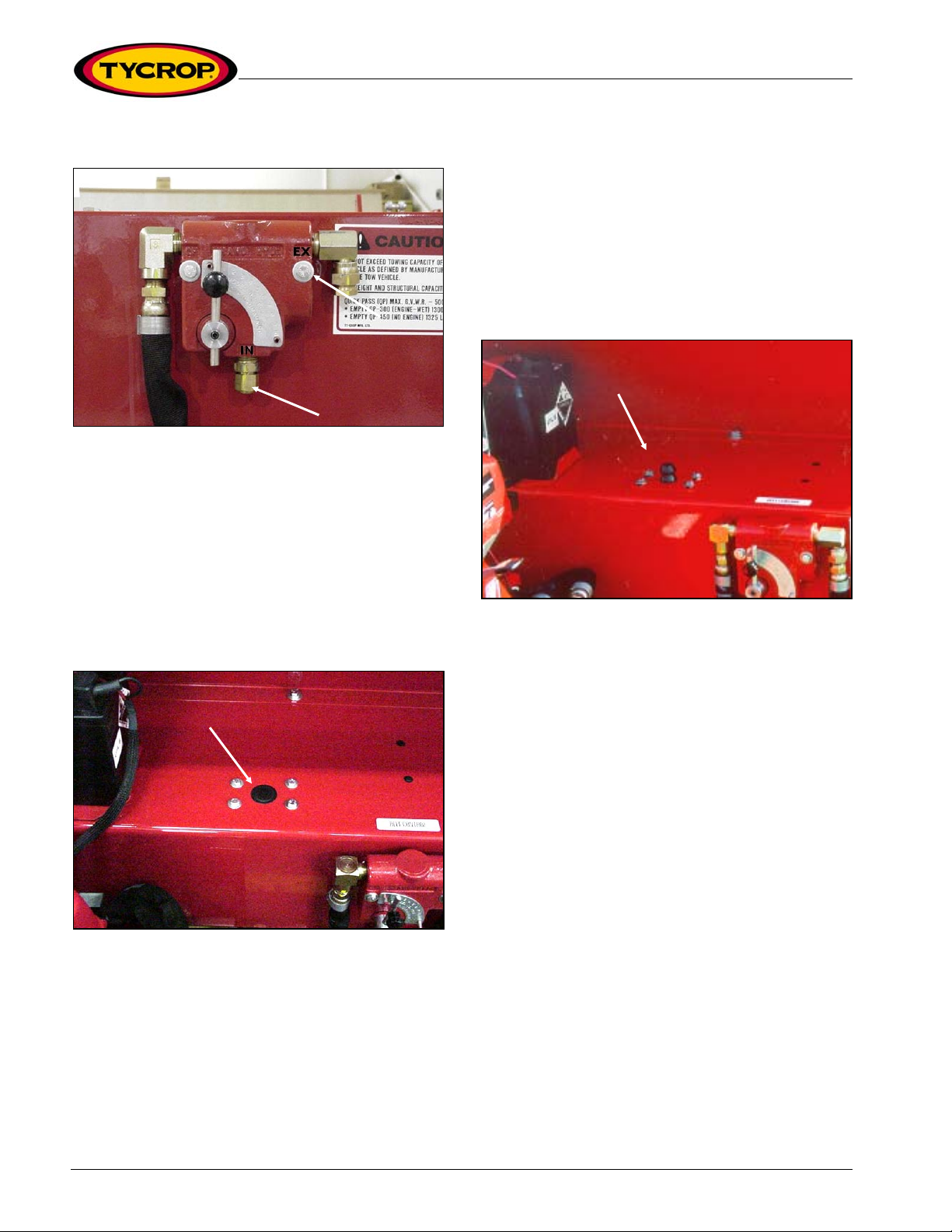
Figure 11: Remove bolts and black plug ...................................................................4
Figure 12: Install hood stop adjuster plate.................................................................4
Figure 13: Schematic of hydraulic connections for Honda engine ............................5
Figure 14: Mount weight case onto hitch...................................................................5
Figure 15: Attach pogo stick on hitch.........................................................................6
Figure 16: Connect return hose and hydraulic fitting.................................................6
Figure 17: Schematic of hydraulic connections for weight case................................7
Figure 18: Remove existing hose ..............................................................................8
Figure 19: Remove hydraulic line clamps from weight case .....................................8
Figure 20: Remove male-to-male junction fitting .......................................................8
Figure 21: Schematic of on/off pendant switch and hydraulics .................................9
Figure 22: Loosen hose at end of tee fitting on ‘B’ port...........................................10
Figure 23: Schematic of electrical components.......................................................11
Figure 24: Remove hopper mounting bolts from chassis ........................................12
Figure 25: Install left and right hopper walls ............................................................12