Mopar Dodge User manual

1
BACKUPCAMERA
DODGE/CHRYSLER
CALLOUTDESCRIPTIONQUANTITY
1Backupcameraharness1
2BackupcameraharnesstoTelematicsGatewayModule
(TGM)connector
1
3Backupcameraconnector1
4Zipties12
5Highmountbrakelampwithtrunkreleasebuttonandbackup
camera
1
6SpliceKit(includes2splicecollarsandshrinktube)1
NOTE:AllviewsareDodgeunlessnoteddifferent,Chryslersimilar.
Nov16,2010K6861117

2
BackUpCameraHarnessRouting
PROCEDURESTEPS:
1.TilttheRHseatbackforaccesstotheBpillarlower
panelretainingscrew(notshown,underthecover,2),
ifequipped.
2.Ifequipped,usingtrimstickC4755orequivalent,re
movetheRHBpillarlowertrimpanelscrewcoverand
removetheretainingscrew.
Nov16,2010K6861117

3
3.Applytheparkingbrake.
4.PlacetheignitionswitchtotheOnposition,applythe
servicebrakesandplacethegearselectorleverinto
theNeutralposition.
5.PlacetheignitionswitchtotheOffposition.
6.Usingasmallflatbladedtoolorequivalent,separate
theretainingring(1)andslidedowntheshiftershaft.
7.Removethesparetirecover/trunkfloorcarpetfromoverthesparetirewell.
8.Disconnectandisolatethebatterynegativecable.
Nov16,2010K6861117

4
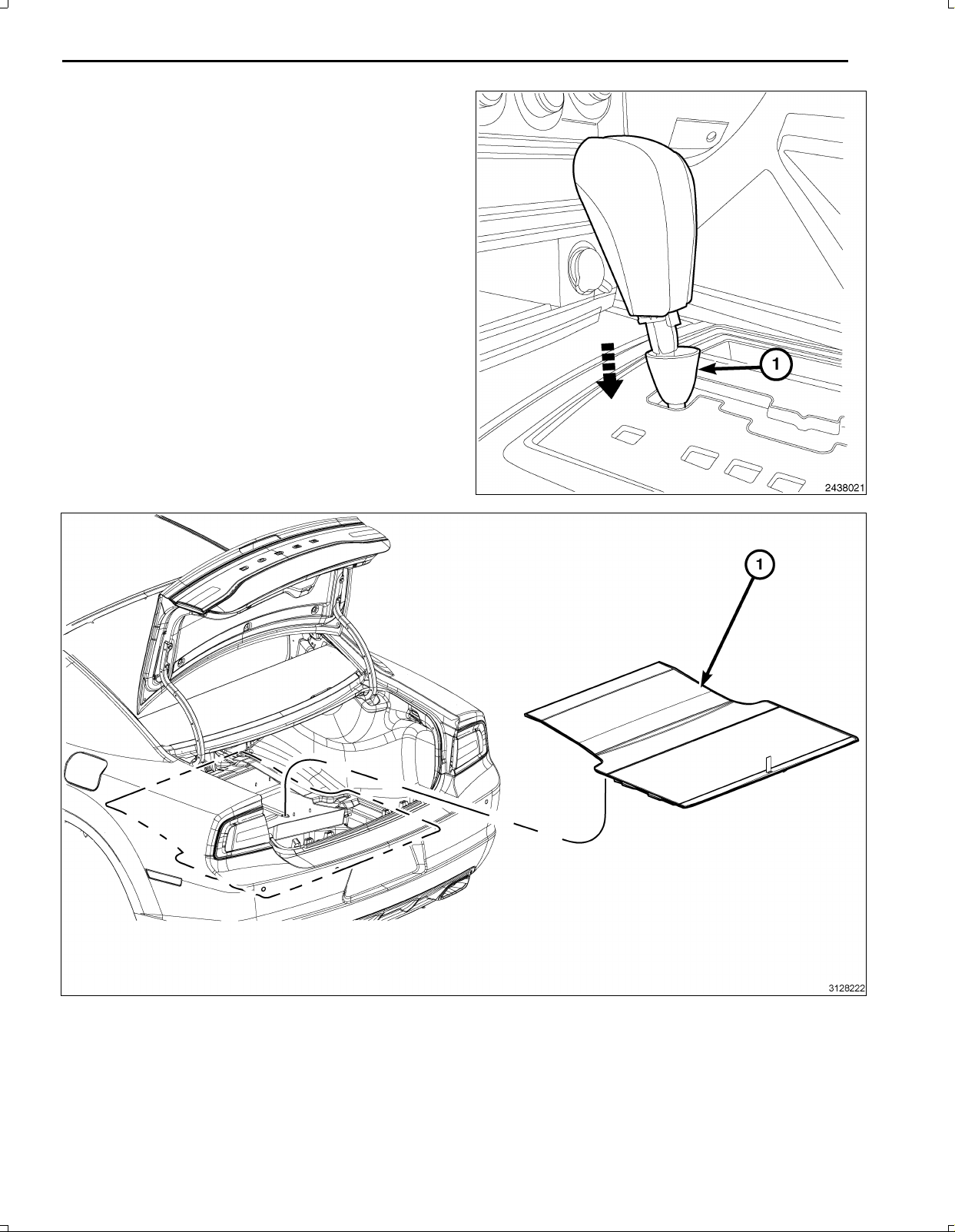
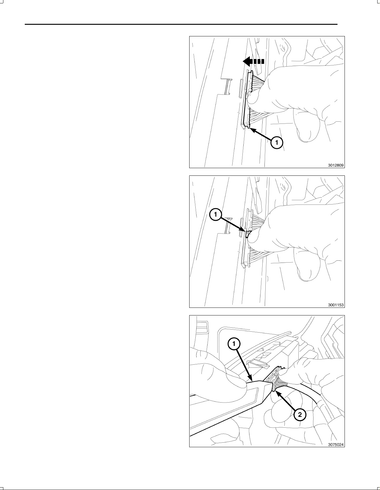
9.Usingathinwiretypetool,locateandpressthere
leasewhilepullingupontheshifterknob(3).
10.Removetheshifterknob(3)andretainingring(2).
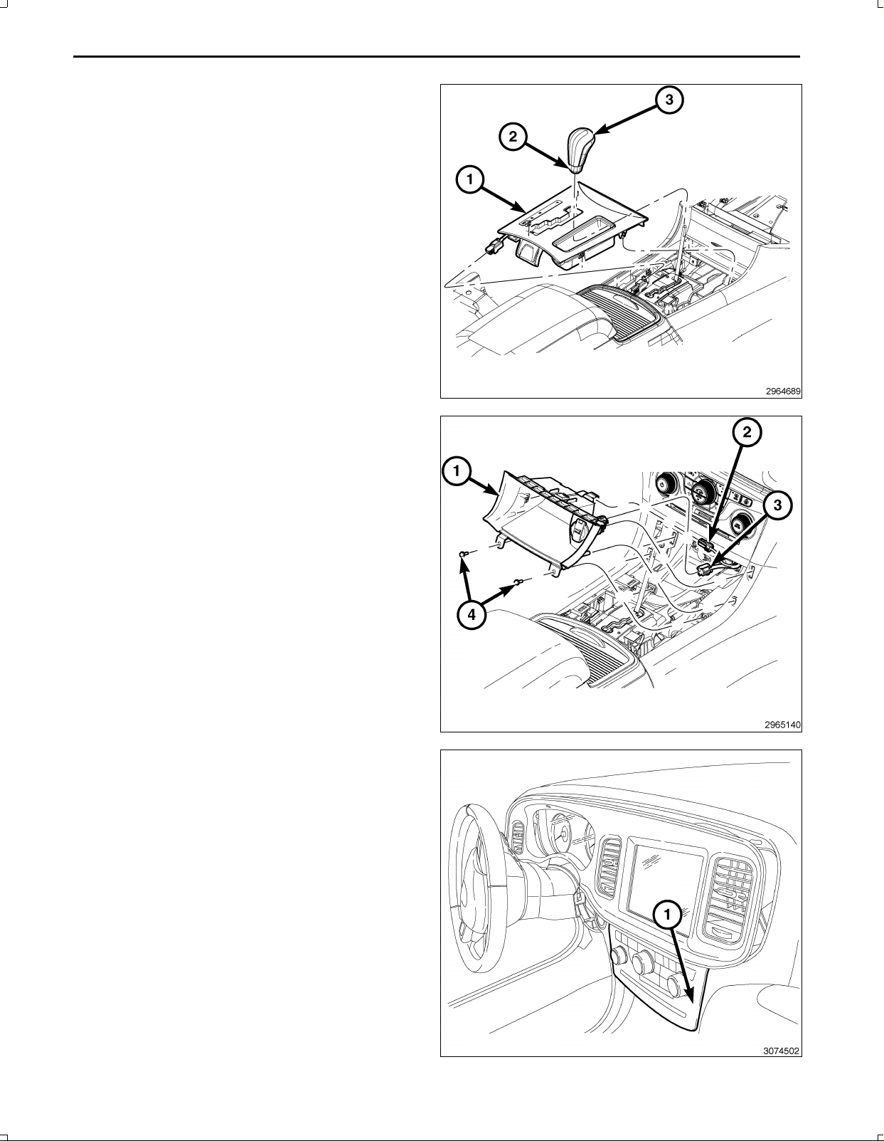
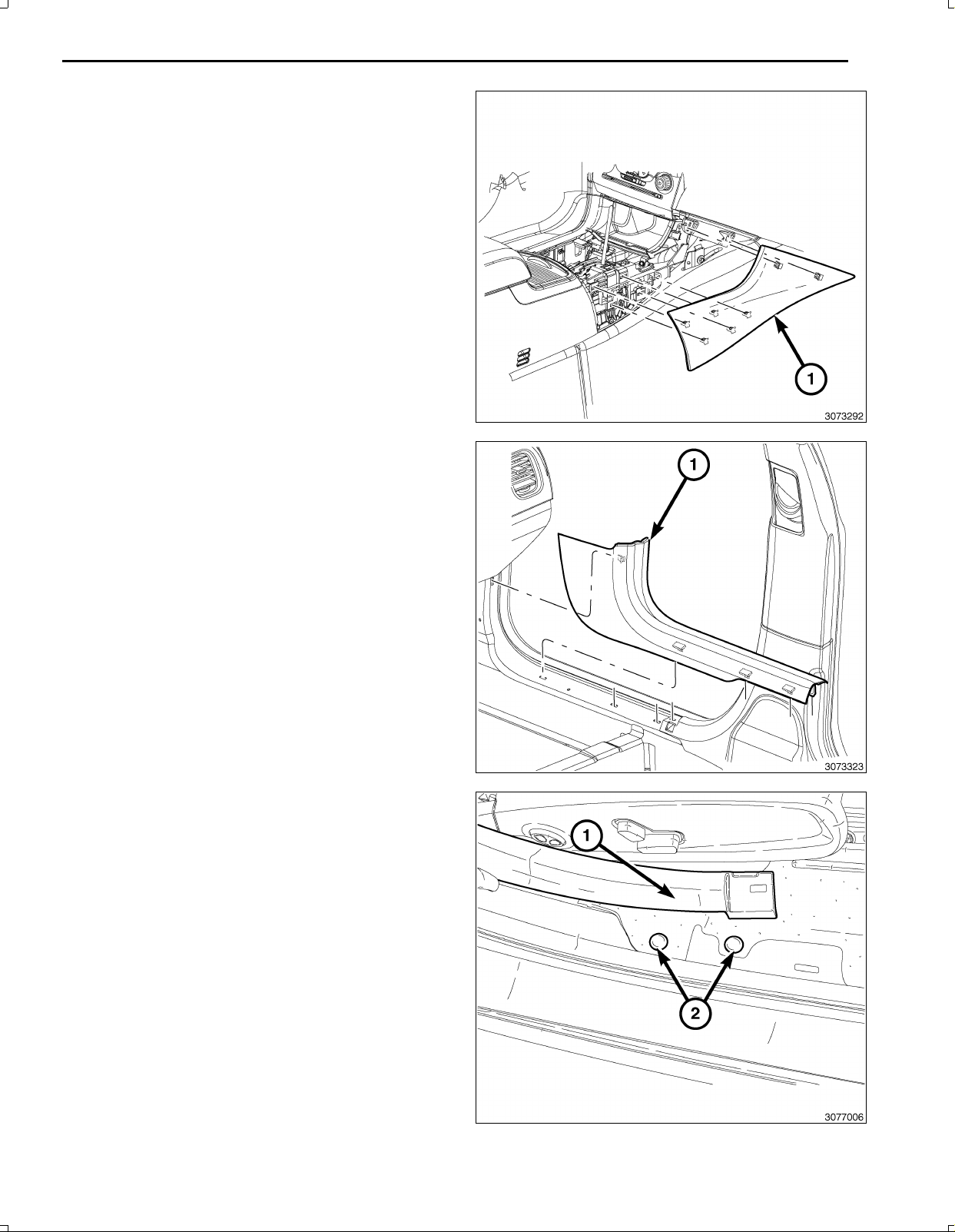
11.UsingatrimstickC4755orequivalent,gentlyprybe
tweentheshifterbezel(1)andthefloorconsoletore
leasethesnapretainersthatsecurethebezel.Donot
pullwithexcessiveforceorfullyremoveatthis
time.
12.Disconnecttheshifterbezelwiringharnessandre
movetheshifterbezel(1).
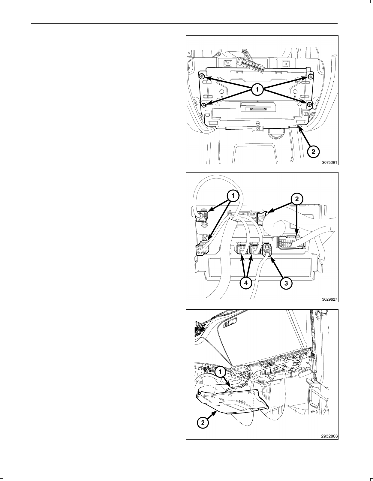
13.Removethetwoscrews(4)securingthestoragebin
(1)totheconsole.
14.UsingatrimstickC4755orequivalent,gentlypry
betweenthestoragebin(1)andthefloorconsole
sidecloseoutpaneltoreleasethetwosnapretainers
thatsecurethestoragebin(1)tothefrontconsole
andcloseoutpanel.
15.Disconnectthe12Vignitionpoweroutletwiringhar
ness(3)fromtherearofthestoragebin(1).
16.DisconnecttheLED/Lampwiringharness(2)fromthe
storagebin(1)andremovethestoragebinfromthe
I/P.
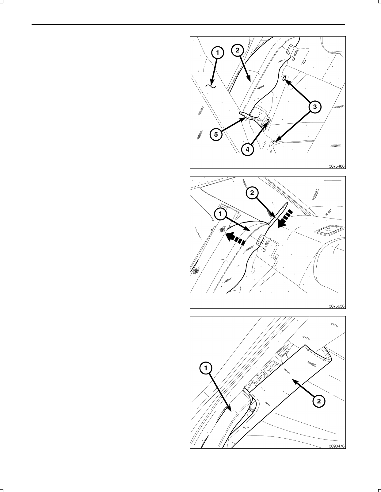
NOTE:Onlydisconnecttheswitchbankassembly
wiringharnessconnectorbyfollowingthespecific
stepsfollowingthisstep.
17.UsingatrimstickC4755orequivalent,gentlyprybe
tweentheswitchbankassembly(1)andtheinstru
mentpaneltoreleasethesnapretainersthatsecure
theswitchbankassembly(1)totheinstrumentpanel
andpullawayfrominstrumentpanelforaccesstore
movetheconnectorusingthefollowingsteps:
Nov16,2010K6861117

5
CAUTION:Neverpulltheconnectoroutbythewires.
Failuretofollowtheseinstructionswilldamageor
breakthewiresand/orconnector.
CAUTION:Pushthe40wayconnectorinbeforepush
ingonthelockingclip.Failuretofollowtheseinstruc
tionswilldamageorbreaktheconnectorlockingclip.
18.Pushinonthe40wayconnector(1)oftheswitchbank
assembly.
19.Gentlypushdownontheconnectorreleaselock(1).
20.UsingapocketscrewdriveroratrimstickC4755or
equivalent(1),gentlypryononesideoftheconnector
(2)toremove.
Nov16,2010K6861117

6
21.Removetheretainers(1)fromtheTelematicsGate
wayModule(TGM)(2)andpulloutfarenoughtoac
cesstheconnectorsonthebackoftheTGM.
CAUTION:Pullingtheantennacablestraightoutofthe
radiowithoutpullingonthelockingantennaconnec
torcoulddamagethecableorradio.
22.Disconnecttheantenna(s)(1),RFHUBandUCIca
bles(4),videocable(3)andwiringconnectors(2)from
theTGM.
23.RemovetheTGMfromthevehicle.
24.Removetherightsideinstrumentpanelsilencerpush
inretainers.
25.DisconnecttheLEDharness(1)andremovetheright
sideinstrumentpanelsilencer(2).
Nov16,2010K6861117

7
26.OntheRHsideandusingatrimstickC4755orequiv
alent,gentlyprybetweentheinstrumentpanelandthe
floorconsolesidecloseoutpanel(1)toreleasethe
twosnapretainersthatsecurethecloseoutpanelto
theinstrumentpanel.
27.UsingatrimstickC4755orequivalent,gentlyprybe
tweenthefloorconsolesidecloseoutpanel(1)and
thefloorconsoletoreleasethefivesnapretainersthat
securethecloseoutpaneltothefloorconsoleandre
movethepanel.
28.UsingatrimstickC4755orequivalent,removethe
RHfrontdoorscuffplate(1).
29.RemovetheRHreardoorscuffplatethesameasthe
front.
NOTE:ItisnotnecessarytoremovetheBpillartrim,
onlyloosenforaccesstoroutethebackupcamera
wiringharness.
30.AtthefrontoftheRHBpillarlowertrim,pullupand
towardtheseattoreleaseretainerclips.Repeatat
therearoftheBpillartrimtoloosenthelowerportion
oftrim.
31.Removeallcarpetpushinfastenersalongthefront
andrearscuffplatesandtheRHkickpanelarea.
Nov16,2010K6861117

8
32.PulltheRHrearseatback(1)forward,exposingthe
luggagecompartment.
33.BehindtheRHrearseat,pullthecarpettab(5)up,
exposingtherearseatbacksidebolsterbracketre
tainingbolt(4).
34.RemovetheRHrearseatbacksidebolsterbracket
bolt(4).
35.Removethepushinfasteners(3)thatsecurethe
trunksidetrim.
36.UsingatrimstickC4755(2)orequivalent,pushdown
betweentherearshelfandtheRHrearseatbackbol
ster(1)toreleasetheretainingclip,andpullouton
theseatbackbolster(1)toremove.
37.Dodgeonly,usingatrimstickC4755orequivalent,
carefullyprythequartertrim(2)looseenoughtore
moveCpillartrim(1).
Nov16,2010K6861117

9
38.Chrysleronly,usingatrimstickC4755orequivalent,
carefullyprythequartertrim(1)atthreepoints(2)
looseenoughtoremovetheCpillartrim(3).
39.UsingatrimstickC4755orequivalent,carefullypry
theCpillartrim(1)inwardtoloosenthepushinre
tainers,thenpullforwardanddowntoremovefrom
thevehicle.
40.Foldbacktheinsulator(2)toexposewiringharness
routingarea.
41.Openthevehicletrunk.
42.RemoveRHhingetrimpushinfasteners(2)andre
movethehingetrim(1).
Nov16,2010K6861117

10
NOTE:Themanualtrunkreleasehandle(2)mustbe
routedthroughthedecklidtrim.
43.Removethetwobumperstops(3)andthenine
pushinretainers(1)fromthedecklidandremove
thedecklidtrimfromthedecklid.
44.Removethewheelwellcovertrimasfollows:
a.OntheRHside,removethecargonethookscrew
(1)anduppercargohook(2).
b.OntheRHside,removethepushinretainer(3)
thatsecuresthewheelwellcovertrim.
c.OntheRHside,removethecargonetlowerhooks
(5).
d.Carefullypullbackthewheelwellcoverenoughto
disconnectthetrunklamp(4)harnessconnector,
andremovethewheelwellcovertrim.
45.Disconnecttheswitchandlampelectricalharness
connectors(2,3).
NOTE:Afterremovingthenuts(1)thereareretaining
tabsnexttothestudsthatneedtobepushedinward
toremovethelampassembly.
46.Removethelampassemblynuts(1)andremovethe
lampassemblyfromthevehicle.
Nov16,2010K6861117

11
NOTE:Ensurewhenroutingthewirenottodamage
thewireterminals.
47.Feedthebackupcamerawiringharness(2)through
thelowerI/P(1)forconnectingtothe12Vignition
poweroutletwiringharnessandtheTGM.
48.Removeenoughoftheinsulatingtape(1)fromthe
wiresofthe12Vignitionpoweroutletwiringharness
connector(2)tospliceintothetwowires.
49.Preparetocrimp/splicethebackupcamerapowerwire
(PK/OR)tothe(DB/PK)ofthe12Vignitionpowerout
letwiringharnessconnectorasfollows:
a.Cutthe12VignitionpoweroutletDB/PKwire.
b.Remove13mm(0.5in.)ofinsulationfromeach
wirethatneedstobespliced.
c.Placeapieceofadhesivelinedheatshrinktubing
(2)ononesideofthewire.Makesurethetubing
willbelongenoughtocoverandsealtheentire
repairarea.
d.Placethestrandsofwireoverlappingeachother
insideofthespliceclip(1).
Nov16,2010K6861117

12
50.Usingcrimpingtool(1),Mopar®p/n05019912AAor
equivalent,crimpthespliceclipandwirestogether.
CAUTION:Donotuseacidcoresolder.
51.Usingasoldertool(3),soldertheconnection(2)to
getherwithrosincoresolder(1).
Nov16,2010K6861117

13
52.Centertheheatshrinktubing(2)overthesolderjoint
andheatusingaheatgun.Heatthejointuntilthetub
ingistightlysealedandsealant(1)comesoutofboth
endsofthetubing.
53.Crimp/splicethebackupcameragroundwire(BK)to
theground(BK)ofthe12Vignitionpoweroutletwiring
harnessconnectorasabove.
NOTE:Theremayalreadybea22pinconnectorcon
nectedtotheTGM.Usethatoneanddiscardtheone
suppliedinthekit.
54.BackouttheconnectorwirelockingtabfromtheTGM
harnessconnector3.
55.InsertthecameraharnesswiresintoTGMharness
connector3asfollows:
a.Signalwire(GY/LB)cavity15
b.Returnwire(GY/OR)cavity16
c.Shieldwire(Bare)cavity17
Nov16,2010K6861117

14
56.Connecttheantenna(s)(1),RFHUBandUCIcables
(4),videocable(3)andwiringconnectors(2)tothe
TGM.
NOTE:Makesurethe40wayconnector(1)ofthe
switchbankassemblyispositionedabovethe
TGMforaccesswhenconnectingtheswitchbank
assembly.
57.PositiontheTGM(2)andinstalltheretainingscrews
(1)totheTelematicsGatewayModule(TGM)(2).
58.Connectthe40wayconnector(1)oftheswitchbank
assembly.
Nov16,2010K6861117

15
59.Positiontheswitchbankassembly(1)andfirmlypress
intoinstrumentpaneltosecurethesnapretainers.
60.Positionthefloorconsolesidecloseoutpanel(1)and
firmlypressintoplacesecuringthetwosnapretain
ersthatsecurethecloseoutpaneltotheinstrument
panel,andthefivesnapretainersthatsecuretheclose
outpaneltothefloorconsole.
61.ConnecttheLED/Lampwiringharness(2)tothestor
agebin(1).
62.Connectthe12Vignitionpoweroutletwiringharness
(3)totherearofthestoragebin(1).
63.Positionthestoragebin(1)andfirmlypushintoplace
securingthetwosnapretainerstothefloorconsole
sidecloseoutpanel.
64.Installthescrews(4)securingthestoragebin(1)to
theconsole.
Nov16,2010K6861117

16
65.Routethebackupcamerawireharness(3)underthe
rightsideoftheI/Pandsecuretothevehicleharness
(2)withtiestraps(1).
66.Routethebackupcamerawireharness(3)underthe
edgeofthecarpet(1)belowtheRHscuffplatesand
theBpillarlowertrim.Attachtothevehiclewiringhar
ness(2)withtiestraps(4)wherenecessary.
67.Feedthebackupcamerawireharness(3)throughthe
bodypanelopening(1)behindtherearseatinsulation
(2)intothetrunkarea.
68.Repositiontheinsulation(2).
Nov16,2010K6861117

17
69.Backouttheconnectorterminallockingtabfromthe
backupcameraconnector.
70.Insertthebackupcameraharnesswiresintobackup
cameraconnectorasfollows:
a.12Vignitionpowerwire(PK/OR)cavity2
b.Signalreturnwire(GY/OR)cavity3
c.Signalwire(GY/LB)cavity4
d.Shieldwire(Bare)cavity7
e.Groundwire(BK)cavity8
71.Positionthelampassemblywithbackupcameraand
installtheretainingnuts(1).
72.Connecttheswitchandlampelectricalharnesscon
nectors(5,6).
73.Routethebackupcameraharness(3)withthetrunk
harnessandattachwithtiestraps(2)asnecessary.
74.Connectthebackupcameraconnectors(4)together.
75.Routethebackupcameraharness(3)downthetrunk
hinge(2)andattachusingtiestraps(4)asnecessary.
76.Bundletheexcessharness(1)togetherusingatie
strap(4).
77.Tucktheharnessbundle(1)abovethewheelwellse
curingoutofthetrunk/hingemovementareausingtie
straps(4)asnecessary.
78.Tucktheinsulatingmaterial(6)throughtheaccess
holewherethebackupharness(5)comesthrough
thebodypaneltoprotectfromchaffing.
Nov16,2010K6861117

18
79.Installthewheelwellcovertrimasfollows:
a.Positionthewheelwellcoverandconnectthe
trunklamp(4)harnessconnector.
b.Installthecargonetlowerhooks(5).
c.Installthepushinretainer(3)thatsecuresthe
wheelwellcovertrim.
d.Installthecargonethookscrew(1)andupper
cargohook(2).
NOTE:Themanualtrunkreleasehandle(2)mustbe
routedthroughthedecklidtrim.
80.Positionthedecklidtrim,installtheninepushinre
tainers(1)andtwobumperstops(3).tothedecklid.
81.PositiontheRHhingetrim(1)andinstallthepushin
fasteners(2).
Nov16,2010K6861117

19
82.Dodgeonly,carefullypositiontheCpillartrim(1),and
fullsecureintoplacewiththepushinfasteners,then
Securethequartertrim(2)withthepushinfasteners.
83.Chrysleronly,removethethreefastenersfromtheup
perportionoftheCpillartrim(1)andinstallonbody
thebody(2).SlidetheCpillartrim(1,3)uptoengage
thethreefasteners(2)andsecurethelowerportionof
theCpillartrim(3)withthepushinfasteners.
84.Positiontherearseatbackbolster(1)andpushinto
engagetheupperclipintothebody.
Nov16,2010K6861117

20
85.Positiontheforwardportionofthetrunksidetrimand
installthepushpinfasteners(3)tosecurethetrunk
sidetrim.
86.InstalltheRHrearseatbacksidebolsterbracketbolt
(4).
87.Repositionthecarpettab(5),coveringtherearseat
backsidebolsterbracketretainingbolt(4).
88.Installallcarpetpushpinfasteners(2)alongthefront
andrearscuffplatesandtheRHkickpanelarea.
89.AttachtheRHBpillarlowertrim(1)bysecuringthe
retainerclipsatthelowerportionofthetrim.
90.Ifequipped,installtheRHBpillarlowertrimpanelre
tainingscrewandscrewcover(2).
Nov16,2010K6861117
This manual suits for next models
1
Table of contents
Languages:
Other Mopar Car Video System manuals

Mopar
Mopar DVD REAR SEAT VIDEO SYSTEM User manual

Mopar
Mopar DVD REAR SEAT VIDEO SYSTEM User manual

Mopar
Mopar K6862043 User manual

Mopar
Mopar 82210914AB User manual

Mopar
Mopar Journey User manual

Mopar
Mopar CHRYSLER PACIFICA User manual

Mopar
Mopar 82208655AB User manual

Mopar
Mopar DVD REAR SEAT VIDEO SYSTEM User manual
Popular Car Video System manuals by other brands

Hyundai
Hyundai Veloster user manual

Hyundai
Hyundai AZERA/GRANDEUR HD instruction manual

SecurView
SecurView SecurView SV-9142.MDM installation instructions

Volkswagen
Volkswagen Composition Touch manual

Speedsignal
Speedsignal B-360DB06 Instructions for use

Clarion
Clarion VM700B Owner's manual & installation manual