Mopar K6862043 User manual

K6862043
3/11/14
1
CALL OUT DESCRIPTION QUANTITY
A1
Radio Harness
B1
TOOLS REQUIRED
rease Pencil
C1
Handle with Camera Provisions
D
E
1
1
Trim Stick
Camera/Lock Jumper Harness
Tailgate Wire Harness
Cable Tie
Phillips Screwdriver
Metric Socket Set
Crimping ToolWire Cutters RTV Sealant 82300234
Backup Camera
Splice Clip
Shrink Tube
F
3
3
Camera Body Harness
H60
www.mopar.com
AC
E
D
H
F
G
B

K6862043
3/11/14
1. Loosen one (1) 10mm bolt and disconnect
negative battery cable
2
NOTE: Veh cle w th ta lgate l ner shown.
The ta lgate l ner and ta lgate cover are
removed and nstalled as one p ece.
2. Open the tailgate.
3. If equipped with tailgate liner (2), remove screws (1)
and remove the tailgate cover.
4. Using a grease pencil or equivalent, mark the
location of the actuator rods (2) at the latch control.
5. Disconnect the actuator rods from the latch control.
www.mopar.com

K6862043
3/11/14
3
6. Remove the two nuts (3) that secure the release
handle (1) and the latch control (2) to the tailgate.
7. Remove the latch control (2) and the release handle
(1) from the tailgate.
11. Position the new handle (C) and the latch control (2)
to the tailgate.
12. Install the two nuts (3) that secure the release handle
and latch control to the tailgate. Tighten the nuts
to 6 N·m (53 in. lbs.).
8. Remove the screws (1) securing the lock cylinder (2)
to the old handle.
9. Transfer the lock cylinder to the new handle (C)
with camera.
10. Install retaining screws and tighten securely.
www.mopar.com
C
C

K6862043
3/11/14
NOTE: If equ pped w th a power lock actuator, remove
and d scard the lock actuator harness.
13. Connect the supplied harness (E) to the camera and
connect the supplied tailgate harness (D) to harness (E).
NOTE: Tape back the lock actuator connector f
veh cle s not equ pped w th a lock actuator.
14. Connect the lock actuator connector (1) (if equipped).
15. Route tailgate jumper harness (D) through the
tailgate as shown to the tailgate closeout panel (2).
4
www.mopar.com
D
D
E

K6862043
3/11/14
5
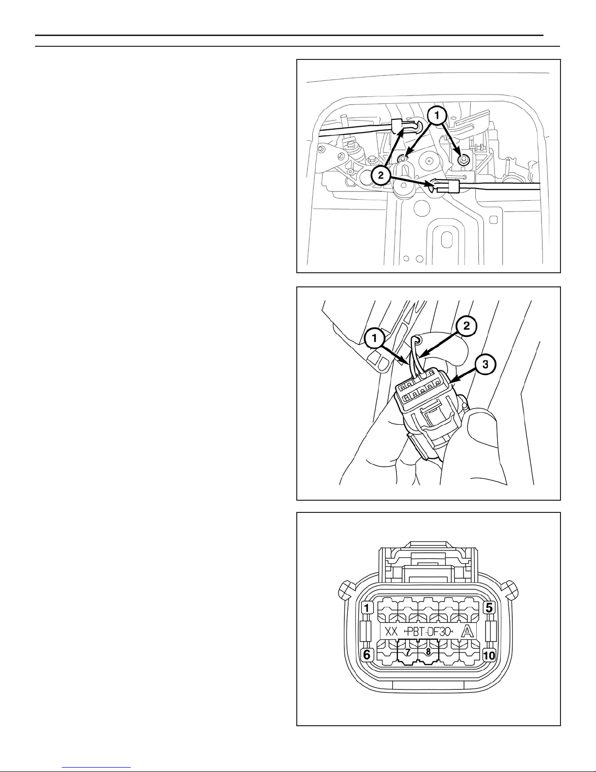
16. Install the actuator rods (2) to the latch control using
the reference marks made during the removal
procedure.
17. Install the tailgate cover and liner (if equipped).
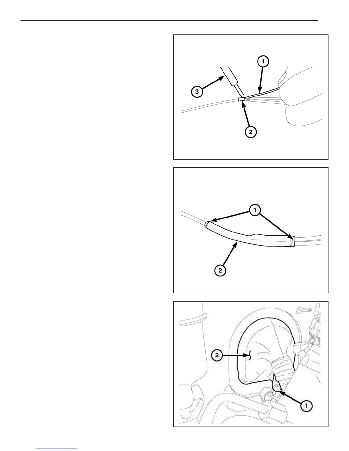
NOTE: If the veh cle s equ pped w th the ta lgate lock
actuator, you must remove and transfer the two
w res from the ex st ng body s de ta lgate
connector to the suppl ed body harness (A)
connector. See graph c for more nformat on.
18. If equipped with the tailgate lock actuator, remove the
wires (1, 2) from the existing tailgate connector (3),
then discard the existing tailgate connector.
19. Remove the terminal plugs from cavities 7 and 8 in
the supplied body harness connector (A).
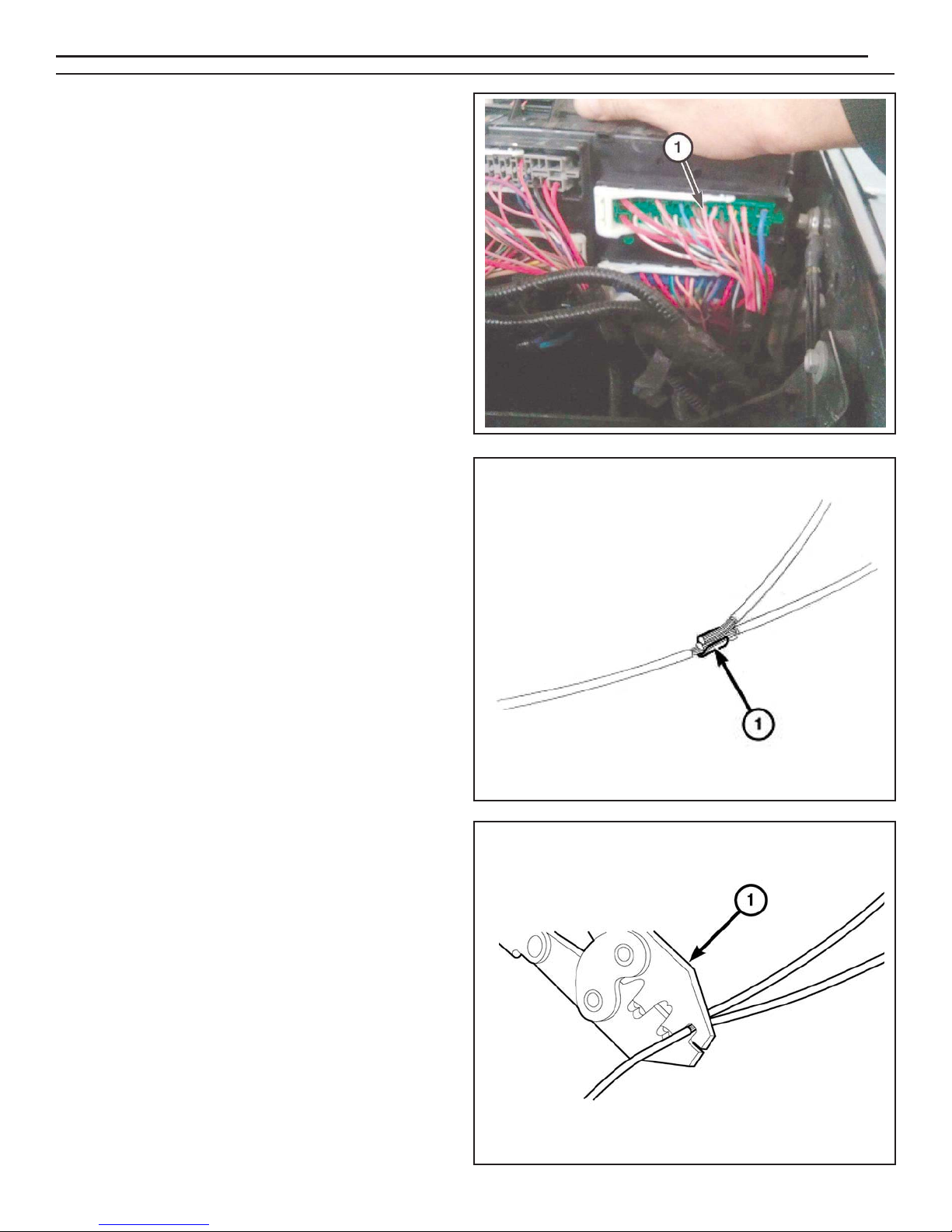
20. Transfer the P237 D /TN wire removed from cavity
7 of the original connector and transfer into cavity 7
of the supplied harness connector.
21. Transfer the P235 L /TN wire removed from cavity 8
of the original connector and transfer into cavity 8 of
the supplied harness connector.
www.mopar.com

K6862043
3/11/14
6
NOTE: When rout ng the body harness, make sure
the harness cannot contact any mov ng parts
or hot exhaust.
22. Route supplied body harness (A) from the back of
the vehicle to the front as shown, following the
existing harness on the driver side. Tie straps must
be used every 150mm to secure harness (A) to
the existing vehicle harness.
23. Remove the ground bolt (2) located on the left
fender next to the Power Distribution Center (PDC).
24. Connect the black wire in the supplied body harness
(A) to the ground location on the fender.
25. Install the ground nut (2). Tighten the ground bolt to
9 N·m (80 in. lbs.).
26. Release the PDC retaining clips (1) and remove the
PDC from the mounting bracket.
www.mopar.com
A
2
1
1

K6862043
3/11/14
7
27. Rotate the PDC to gain access to the underside of
the PDC.
28. Locate circuit F923 (PK/YL) at cavity 13 (1) on the
underside of the PDC.
29. Splice the red wire from the supplied body harness
(C) to the PK/YL (F923) wire at cavity 13 of the PDC
(Splice and solder new wire to the original wire
using the soldering procedure in steps 30 thru 33).
30. Place the strands of the wires overlapping each
other inside of the splice clip (1).
31. Using Mopar® crimping tool (1) or equivalent, crimp
the splice clip and wires together.
www.mopar.com

K6862043
3/11/14
8
32. Solder (3) the connection (2) together using rosin
core solder (1).
33. Center the heat shrink tubing (2) over the solder joint
and heat using a heat gun. Heat the joint until the
tubing is tightly sealed and sealant (1) comes out of
both ends of the tubing.
34. Install the PDC to its original mounting location by
pressing it back into place.
35. Route the remaining supplied body harness (A) to
the body grommet on driver side bulkhead.
36. Cut the end off the dash panel grommet nipple (1)
hanging off the bottom side of the body harness
near the brake booster.
37. Route the backup camera harness through the dash
panel grommet nipple.
38. Apply MoparT RTV 82300234 around the grommet
nipple.
www.mopar.com

K6862043
3/11/14
9
39. Continue to route the supplied body harness (A) to
the driver kick panel area.
40. Insert wires into supplied connector (taped to
harness in polybag) as listed below:
Cavity A RY/BLU
Cavity B YEL
Cavity C - RN
Cavity D RY/OR
Cavity E Bare
Cavity F - BLU
41. Release and remove connector C5 (1) from the
Body Control Module (BCM).
42. Remove the housing (2) to gain access to the
terminal blocks (1).
www.mopar.com

K6862043
3/11/14
10
NOTE: Connector C5 front v ew s shown.
43. Insert the purple wire from supplied harness (A)
into connector C5 cavity 45. If the cavity is already
populated, cut the terminal off the purple wire and
splice the purple wire to the OR /DB wire in cavity 45
(Splice and solder new wire to the original wire using
the soldering procedure in steps 30 thru 33).
NOTE: Yellow w re s not used. Tape back onto harness.
44. Assemble connector C5 and insert back into BCM.
NOTE: Be sure to keep all fasteners for later
re nstallat on.
45. Remove the storage tray cover (1) from the top center
area of the dashboard. Remove fasteners (2) from the
storage tray (3). Remove the tray.
46. Remove the storage tray (1) from the front of the
center console.
2
1
1
3
www.mopar.com

K6862043
3/11/14
11
49. Remove fastener (1) from the storage cubby on the
right side of the center dash trim panel. Carefully
disengage all retainer clips and pry off the trim panel (2).
47. Remove the edge trim (1) from the center console
cover panel.
48. Remove fasteners (1) at the front edge of the center
console cover panel (2). Remove the cover panel.
1
www.mopar.com
2
1
2
1

K6862043
3/11/14
12
50. Disconnect all plugs from the back of panel (1).
Remove the panel from the vehicle.
51. Remove fasteners (2) from the radio assembly.
52. Remove radio assembly (1) from dash. Unlock the
the 52-way connector (2) at the back of the radio and
disconnect.
53. Route the radio harness (B) under the dashboard and
up to the center stack. Secure harness with cable
ties (H).
NOTE: Cable t es should be nstalled no farther
than 100mm apart.
www.mopar.com
2
1
2
1
H
B

K6862043
3/11/14
13
55. If necessary, depopulate the three ex st ng w res
nd cated from the connector and tape back onto
the harness. Insert the new wires from the
camera harness as follows:
Cavity 31 RY/BLU
Cavity 32 RY/ORA
Cavity 33 - Bare
56. Check all wiring and trim all cable ties.
57. Reconnect the battery.
58. Reverse steps 45 through 52, 26, and 3 to re nstall all veh cle components.
59. Follow the Vehicle Configuration Instructions on the next page.
54. Feed the three-prong end of radio harness (B) up into
the center stack and out through the radio opening.
NOTE: Use M ller 6680 Depopulate Tool to remove w res.
B
www.mopar.com
B
PIN 31
PIN 32
PIN 33

K6862043
3/11/14
14
RAM CAMERA VEHICLE CONFIGURATION
Vehicle VIN must be updated with the sales code of the added accessory in order to enable system
functionality. Using the DealerCONNECT website and the scan tool, complete the procedure below:
1. Log on to https://dealerconnect.chrysler.com
2. In the service tab, inside the Warranty Administration box, locate Vehicle Option Updates.
Enter the vehicle VIN and add the sales code XAC (Park View Rear BackUp Camera) as a
Dealer Installed Option.
3. Confirm that the new sales code has been successfully added to the VIN. With the scan tool
connected to both the internet (via Ethernet port or wireless connection) and the vehicle, follow
the steps below:
4. Using the scan tool select the VEHICLE PREPARATION and then select
RESTORE VEHICLE CONFI URATION.
5. Follow the step by step instructions on the scan tool to complete the Park View Rear BackUp
Camera vehicle configuration.
6. When the Park View Rear BackUp Camera Vehicle Configuration is complete, go to the
Validation Process to verify that the vehicle has been updated.
VALIDATION PROCESS
From the Initial Start Up screen on the scan tool follow the steps below:
1. Using the scan tool follow the menu to ECU VIEW, select TIPMC W CENTRAL ATEWAY,
MORE OPTIONS, ECU DETAILS and then CONFI INFO
2. Verify REAR CAMERA SET is present.
3. Clear any DTCs that may have been set. Some modules may have to be initialized after the
reconfiguration.
www.mopar.com

K6862043
3/11/14
1
A1
Harnais de radio
B1
Crayon gras
C1
Poignée avec dispositions pour caméra
D
E
1
1
Caméra et faisceau de cava ier de verroui age
Faisceau de câb age du hayon
Attache-câb es
Pince à sertirRTV mastic 82300234
CAMÉRA DAIDE AU RECUL
Trousse de jonction
Tube thermorétrécissab e
F
G
3
3
Caméra et faisceau de carrosserie
H60
RÉFÉRENCE DESCRIPTION QUANTITÉ
OUTILS REQUIS
Ensemb e de doui es métriques Tournevis Phi ips Outi pour garnitures
Coupe-fi
www.mopar.com
AC
E
D
H
F
G
B

K6862043
3/11/14
2
NOTA : Véh cule avec garn ture de hayon llustré.
La garn ture et le couvercle du hayon sont ret rés
et nstallés en un bloc.
2. Ouvrez e hayon.
3. Si e véhicu e est équipé de a garniture de hayon (2),
retirez es vis (1) et en ever e couverc e de hayon.
4. À aide dun crayon gras ou dun outi équiva ent,
marquez emp acement des tiges dactionneur (2)
au niveau de a commande de oquet.
5. Débranchez es tiges dactionneur de a commande
de oquet.
1. Déconnectez e câb e négatif de accumu ateur en
desserrant un (1) bou on de 10 mm.
www.mopar.com

K6862043
3/11/14
3
6. Retirez es deux écrous (3) qui fixent a poignée de
déverroui age (1) et a commande de oquet (2)
au hayon.
7. Retirez a commande de oquet (2) et a poignée de
déverroui age (1) du hayon.
11. P acez a nouve e poignée (C) et a commande
de oquet (2) sur e hayon.
12. Insta ez es deux écrous (3) qui fixent a poignée de
déverroui age et a commande de oquet au hayon.
Serrez es écrous au coup e de 6 N.m (53 b-po).
8. Retirez es vis (1) qui fixent e bari et de serrure (2)
à a viei e poignée.
9. Transférez e bari et de serrure à a nouve e poignée
avec a caméra (C).
10. Insta ez es vis de fixation et serrez- es so idement.
www.mopar.com
C
C

K6862043
3/11/14
NOTA : S le véh cule est équ pé dun act onneur de
serrure électr que, ret rez le fa sceau dact onneur de
serrure et mettez-le au rebut.
13. Brancher e faisceau (E) à a caméra. Connectez
harnais (D) à exp oiter (E).
NOTA : Placez le connecteur dact onneur de serrure
vers larr ère à la de de ruban adhés f s le véh cule
nest pas équ pé dun act onneur de serrure.
14. Branchez e connecteur dactionneur de serrure (1)
(se on équipement).
15. Acheminez e faisceau de cava ier du hayon (D) dans
e hayon, comme i ustré, vers e panneau de fermeture
du hayon (2).
4
www.mopar.com
D
D
E

K6862043
3/11/14
5
16. Insta ez es tiges dactionneur (2) sur a commande
de oquet au moyen des repères de référence faits
pendant a procédure de dépose.
17. Insta ez e couverc e et a garniture de hayon
(se on équipement).
NOTA : S le véh cule est équ pé de lact onneur de
serrure de hayon, vous devez ret rer les deux f ls du
connecteur de hayon du côté carrosser e ex stant
et les transférer au connecteur de fa sceau de
carrosser e fourn (A). Consultez le graph que pour
obten r de plus amples rense gnements.
18. Si e véhicu e est équipé de actionneur de serrure
de hayon, déposez es câb es (1, 2) du connecteur
de hayon actue (3), puis mettez au rebut e
connecteur de hayon actue .
19. Retirez es fiches de borne des cavités 7 et 8 dans
e connecteur du faisceau de carrosserie fourni (A).
20. Transférez e fi du circuit P237 (DG/TN) qui a été retiré
de a cavité 7 du connecteur dorigine et transférez- e
à a cavité 7 du connecteur de faisceau fourni.
21. Transférez e fi du circuit P235 (LG/TN) qui a été retiré
de a cavité 8 du connecteur dorigine et transférez- e
à a cavité 8 du connecteur de faisceau fourni.
www.mopar.com

K6862043
3/11/14
6
NOTA : Lors de lachem nement du fa sceau de
carrosser e, assurez-vous que le fa sceau ne peut pas
entrer en contact avec les p èces amov bles ou le
système déchappement chaud.
22. Acheminez e faisceau de carrosserie fourni (A) à partir
de arrière du véhicu e jusquà avant, comme i ustré, en
suivant e faisceau existant sur e côté conducteur.
REMARQUE : Les attache-câbles ne devra ent pas
être d stancés de plus de 150 mm.
23. Déposez e bou on de masse (2) situé sur ai e gauche
à côté de a centra e de servitudes (PDC).
24. Connectez e fi noir dans e faisceau de carrosserie
fourni (A) à a masse située sur ai e.
25. Posez e bou on de masse (2). Serrez e bou on de
masse au coup e de 9 N.m (80 b-po).
26. Libérez es agrafes de fixation de a centra e de
servitudes (1) et retirez a centra e du support
de fixation.
www.mopar.com
A
2
1
1
Table of contents
Languages:
Other Mopar Car Video System manuals

Mopar
Mopar DVD REAR SEAT VIDEO SYSTEM User manual

Mopar
Mopar 82210914AB User manual

Mopar
Mopar Journey User manual

Mopar
Mopar DVD REAR SEAT VIDEO SYSTEM User manual

Mopar
Mopar 82208655AB User manual

Mopar
Mopar DVD REAR SEAT VIDEO SYSTEM User manual

Mopar
Mopar Dodge User manual

Mopar
Mopar CHRYSLER PACIFICA User manual
Popular Car Video System manuals by other brands

Philips
Philips CED1500BT user manual

Vizualogic
Vizualogic HindSight Chevy Avalanche installation manual

Blaupunkt
Blaupunkt CHICAGO IVDM-7002 Installation/connections

Beat
Beat Evolve N-1 user manual

Farenheit
Farenheit 10.4" TFT Ceiling Color Monitor user manual

Trailer Vision
Trailer Vision Digi-Lite Solar A1070 user manual