Mopar Journey User manual

1
BACKUPCAMERA
JOURNEY
CALLOUTDESCRIPTIONQUANTITY
1Backupcameraharness1
2BackupcameraharnesstoTelematicsGatewayModule
(TGM)connector
1
3Backupcameraconnector1
4Zipties12
5Liftgatehandlecarrierwithlicenselampsandbackupcamera1
6SpliceKit(includes2splicecollarsandshrinktube)1
ToolsRequired
10mm,15mmSocketand
Ratchet
CrimpingTool,Mopar®p/n
05019912AAorequivalent
ElectricalSolderingKitHeatGun
Feb02,2011K6861161
www.mopar.com

2
ToolsRequired
PhillipsScrewdriverPowerOutletRemover
10246orequivalent
ScanToolT20,T30Torx®Driver
TrimPanelToolTrimStickC4755or
equivalent(1)
WireStrippers
BackUpCameraHarnessRouting
PROCEDURESTEPS:
WARNING:Disabletheairbagsystembeforeattemptinganysteeringwheel,steeringcolumn,orinstrument
panelcomponentdiagnosisorservice.Disconnectandisolatethenegativebattery(ground)cable,thenwait
twominutesfortheairbagsystemcapacitortodischargebeforeperformingfurtherdiagnosisorservice.This
istheonlysurewaytodisabletheairbagsystem.Failuretotaketheproperprecautionsmayresultinaccidental
airbagdeploymentandpossibleseriousorfatalinjury.
1.Disconnectandisolatethebatterynegativecable.
2.UsingtrimstickC4755orequivalent,loosenthe
instrumentpaneltrim(2)locatedrightofthecenter
stackbezelenoughtoaccesstheswitchbank
retainingscrewunderneath.
3.UsingtrimstickC4755orequivalent,removethein
strumentpaneltrim(1)locatedleftofthecenterstack
bezel.
Feb02,2011K6861161
www.mopar.com

3
4.Removethescrews(2)thatsecuretheswitchbank
(1)totheI/P(4).
NOTE:Onlydisconnecttheswitchbankassembly
wiringharnessconnectorbyfollowingthespecific
stepsfollowingthisstep.
5.UsingatrimstickC4755orequivalent,gentlyprybe
tweentheswitchbankassembly(1)andtheinstru
mentpaneltoreleasethesnapretainers(locatedat
3)thatsecuretheswitchbankassembly(1)tothein
strumentpanelandpullawayfrominstrumentpanel
foraccesstoremovetheconnectorusingthefol
lowingsteps:
CAUTION:Neverpulltheconnectoroutbythewires.
Failuretofollowtheseinstructionswilldamageor
breakthewiresand/orconnector.
CAUTION:Pushthe40wayconnectorinbeforepush
ingonthelockingclip.Failuretofollowtheseinstruc
tionswilldamageorbreaktheconnectorlockingclip.
6.Pushinonthe40wayconnector(1)oftheswitchbank
assembly.
7.Gentlypushdownontheconnectorreleaselock(1).
Feb02,2011K6861161
www.mopar.com

4
8.UsingatrimstickC4755orequivalent(1),gentlypry
ononesideoftheconnector(2)toremove.
9.Removetheretainers(1)fromtheTelematicsGate
wayModule(TGM)(2)andpulloutfarenoughtoac
cesstheconnectorsonthebackoftheTGM.
CAUTION:Pullingtheantennacablestraightoutofthe
radiowithoutpullingonthelockingantennaconnec
torcoulddamagethecableorradio.
10.Disconnecttheantenna(s)(1),RFHUBandUCIca
bles(4),videocable(3)andwiringconnectors(2)from
theTGM.
11.RemovetheTGMfromthevehicle.
Feb02,2011K6861161
www.mopar.com

5
NOTE:Seatsremovedforclarity.
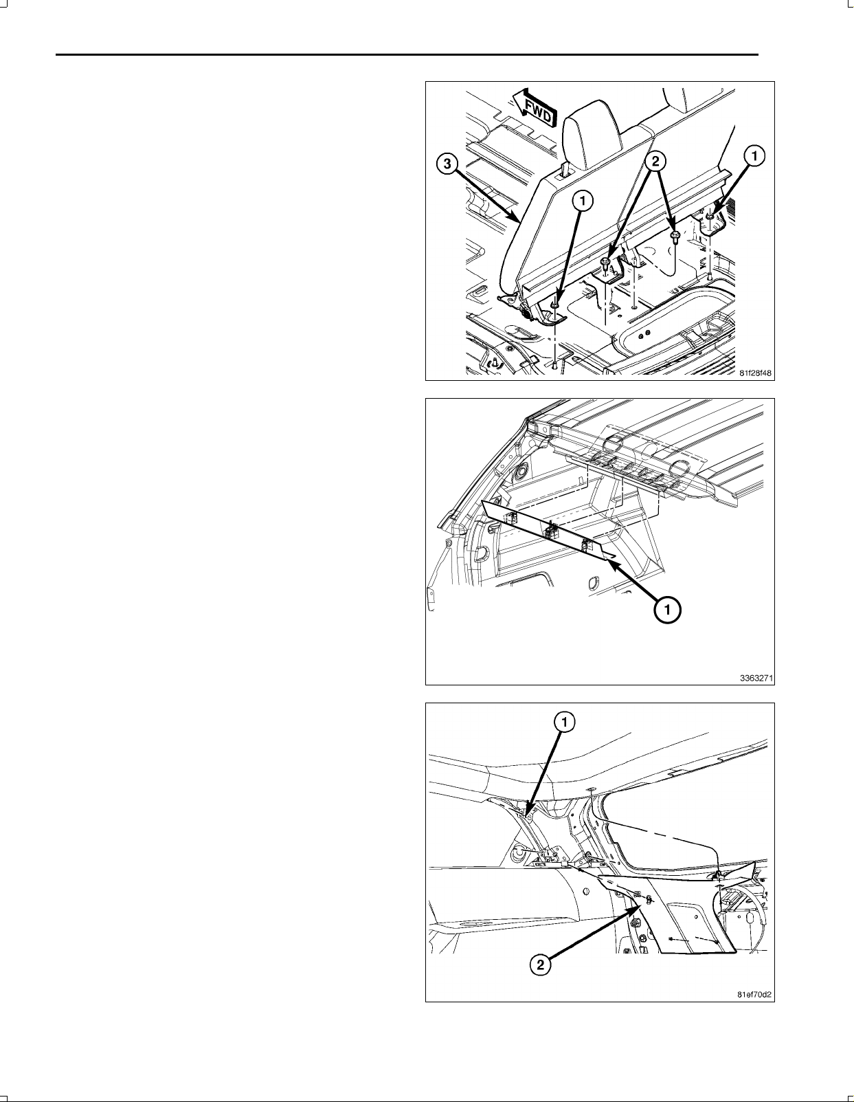
12.UsingtrimstickC4755orequivalent,disengageclips
holdingdoorsillscuffpanel(1).
13.Startingattheforwardendofthedoorsillscuffplate
(1),pullupwardonthesillscuffplateinordertodis
engagetheclips(3)attachingsillscuffplatetodoor
openingflange(4).
14.RemoveLFdoorsillscuffplate(1)fromvehicle.
15.RemovetheLRdoorsillscuffplate(notshown)the
sameasthefront.
16.UsingtrimstickC4755orequivalent,disengage
clipsholdingtheLHkickpanel(2)andremovethe
kickpanel.
NOTE:ItisnotnecessarytoremovetheBpillartrim,
onlyloosenforaccesstoroutethebackupcamera
wiringharness.
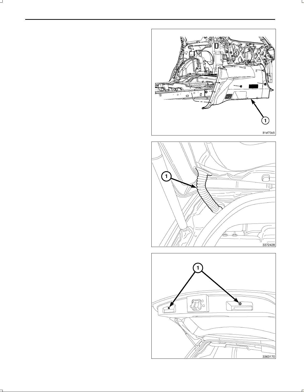
17.UsingtrimstickC4755orequivalent,disengageclips
holdingthelowerportionoftheBpillartrim(5)andpullinwardtoloosenenoughtoroutethebackupcamerawiring
harness.
18.Opentheliftgate.
19.UsingtrimstickC4755,carefullyprytheliftgatesill
plateoutdisengagingtheretainingclips.
20.Removetheliftgatesillplatefromthevehicle.
Feb02,2011K6861161
www.mopar.com

6
NOTE:Storagebinwiththirdrowseatshown,withoutthirdrowseatsimilar.
21.Ifequippedwithathirdrowseat,removetheretainersontheseatbackgaphidertotherearstorageboxandopen
thestorageboxlid(3).
22.Ifequipped,removethematorloadfloorassemblycoveringthestoragebox.
23.Ifequipped,removethestorageboxliner(2).
24.Removethefourstorageboxmountingfasteners(4).
25.Removethestoragebox(1)fromthevehicle.
26.Liftfrontedgeofthethirdrowseatuntilretainers(5)disengage.
27.Withthehelpofanassistant,carefullypryuponthehooks(4)whiletheseatcushionisbeingpressedtowardsthe
seatback.
28.Whileliftinguponthehooks(4),pulltheseatcushion(1)outtowardsthefrontofthevehicleandremovetheseat
cushion.
29.Removetheseatbackfrontmountingfasteners(1).
Feb02,2011K6861161
www.mopar.com

7
30.Removetherearseatbackmountingfasteners(1,2).
31.Removetheseatbackfromthevehicle.
32.Removetherearheadertrimpanel(1)bycarefully
pullingdownonthetrimtodisengagetheretainers.
33.RemovetheDpillartrimaccessholecoversandre
movethemountingfasteners.
34.UsingtrimstickC4755,carefullyprytheDpillartrim
(2)outdisengagingtheretainingclips.
35.RemovetheDpillartrim(2)fromthevehicle.
Feb02,2011K6861161
www.mopar.com

8
36.Removethequartertrimpanelmountingfasteners.
37.UsingtrimstickC4755,carefullyprythequartertrim
panel(1)outdisengagingtheretainingclips.
38.Carefullyremovethequartertrimpanel(1)frombe
tweenthebodyandthesecondrowseat.
39.Disconnectthewiringharnessgrommet(1)fromthe
bodyandtheliftgate.
40.Opentheliftgate.
41.Removethetwolowerscrews(1).
Feb02,2011K6861161
www.mopar.com

9
NOTE:Thesidetrimpanelscanberemovedincon
junctionwiththelowerliftgatetrimpanel.
42.UsingtrimstickC4755orequivalent,disengagethe
sidetrimpanel(2,3)retainingclips.
43.UsingtrimstickC4755orequivalent,pryaroundthe
perimeterofthelowertrimpanel(1)todisengagethe
retainingclips.
44.Positionthelowertrimpanel(1)slightlyawayfrom
thedooranddisconnectthewiringharnessconnector
fromtheliftgatelamp(2).
45.Removethelowertrimpanel(1).
46.Usingasmalltrimtoolorequivalent,separatethe
pushpinfasteners(1)fromtheuppertrimpanel(2).
Repeatontheoppositeside.
Feb02,2011K6861161
www.mopar.com

10
47.UsingtrimstickC4755orequivalent,pryaroundthe
perimeteroftheuppertrimpanel(1)todisengagethe
retainingclipsandremovethetrimpanel.
NOTE:Afterremovingtheretainers(1)therearere
tainingtabsthatneedtobereleasedforremovingthe
lightbar.
48.Removethefourretainers(1)holdingthelightbar(2)
totheliftgate.
49.Usingatrimstickorequivalent,releasethelightbar
fromtheretainingclips.
50.Disconnecttheswitchandlampelectricalharness
connectors(1,2)fromthelightbar(4)asnecessary.
51.Disconnecttheliftgatereleasecable(3)fromthelight
bar/handleanddiscardthelightbar.
Feb02,2011K6861161
www.mopar.com

11
52.Removethe12VignitionpoweroutletfromtheI/P
lowerbinareaasfollows:
a.Lookinsideandnotepositionoftheretainingbosses
(2).
b.InsertPowerOutletRemover10246(1),orequivalent
intotheretainingbosses(2)ofthepoweroutlet.
c.Pulloutthebasethroughthemountingringbygently
rockingthetool.
d.Disconnecttheharnessfromthepoweroutletandset
theoutletaside.
e.Pullthe12Vignitionpoweroutletwiringharnesscon
nectorthroughtheopeninginthebackofthecenter
stackareaforsplicing.
NOTE:TheI/Pendofthebackupcameraharness(2)
hasthetwowireswithoutterminalendsforsplicing
tothe12Vignitionpoweroutletconnector(1).
NOTE:Ensurewhenroutingthewireharnessnotto
damagethewireterminals.
53.Feedthebackupcamerawiringharness(2)fromthe
LHsideoftheI/Pneartheparkbrakepedaloverthe
brakepedalsledandthroughthelowerI/Pandintothe
centerI/Pstackareaforconnectingtothe12Vigni
tionpoweroutletwiringharnessconnector(2)andthe
TGM.Securetothevehicleharnesswithtiestraps.
54.Removeenoughoftheinsulatingtapefromthewires
ofthe12Vignitionpoweroutletwiringharnesscon
nector(1)tospliceintothetwowires.
55.Preparetocrimp/splicethebackupcamerapowerwire
(PK/OR)tothe(DB/PK)ofthe12Vignitionpowerout
letwiringharnessconnectorasfollows:
a.Cutthe12VignitionpoweroutletDB/PKwire.
b.Remove13mm(0.5in.)ofinsulationfromeach
wirethatneedstobespliced.
c.Placeapieceofadhesivelinedheatshrinktubing
(2)ononesideofthewire.Makesurethetubing
willbelongenoughtocoverandsealtheentire
repairarea.
d.Placethestrandsofwireoverlappingeachother
insideofthespliceclip(1).
Feb02,2011K6861161
www.mopar.com

12
56.Usingcrimpingtool(1),Mopar®p/n05019912AAor
equivalent,crimpthespliceclipandwirestogether.
CAUTION:Donotuseacidcoresolder.
57.Usingasoldertool(3),soldertheconnection(2)to
getherwithrosincoresolder(1).
Feb02,2011K6861161
www.mopar.com

13
58.Centertheheatshrinktubing(2)overthesolderjoint
andheatusingaheatgun.Heatthejointuntilthetub
ingistightlysealedandsealant(1)comesoutofboth
endsofthetubing.
59.Crimp/splicethebackupcameragroundwire(BK)to
theground(BK)ofthe12Vignitionpoweroutletwiring
harnessconnectorasabove.
60.Installthe12Vignitionpoweroutletasfollows:
a.Feedthe12Vignitionpoweroutletwiringharnesscon
nector(1)throughtheopeninginthebackofthecenter
stackareaandconnecttothereceptacle(2).
b.Alignthesplinesontheoutsideofthepoweroutletre
ceptaclebaseconnectorreceptaclewiththegrooveson
theinsideofthemount.
c.Installthepoweroutletintothepanelbypressingfirmly
onthepoweroutletreceptaclebaseuntiltheretaining
bossesofthemountarefullyengagedintheirrecepta
cles.
Feb02,2011K6861161
www.mopar.com

14
NOTE:Theremayalreadybea22pinconnectorcon
nectedtotheTGM.Usethatoneanddiscardtheone
suppliedinthekit.
61.BackouttheconnectorwirelockingtabfromtheTGM
harnessconnector3.
62.InsertthecameraharnesswiresintoTGMharness
connector3asfollows:
a.Signalwire(GY/LB)cavity15
b.Returnwire(GY/OR)cavity16
c.Shieldwire(Bare)cavity17
63.Connecttheantenna(s)(1),RFHUBandUCIcables
(4),videocable(3)andwiringconnectors(2)tothe
TGM.
NOTE:Makesurethe40wayconnector(1)ofthe
switchbankassemblyispositionedabovethe
TGMforaccesswhenconnectingtheswitchbank
assembly.
64.PositiontheTGM(2)andinstalltheretainingscrews
(1)totheTelematicsGatewayModule(TGM)(2).
Feb02,2011K6861161
www.mopar.com

15
65.Carefullyconnectthe40wayconnector(1)ofthe
switchbankassembly.
66.PositiontheswitchbankintheI/Pandpressevenly
theengagethetwolowerclips(3).
67.Install,andtightenthetwoscrews(2)thatsecurethe
switchbank(1)totheI/P(4).
68.InstalltheI/Ptrimtotheleftandrightoftheswitch
bank.
NOTE:RoutingundertheI/Pshouldbeabovethe
brakepedalsledandsecuredtoeliminatepossible
interferencewithallpedalmovement.Routing
underthekickpanelshouldbesecuredtoeliminate
possibleinterferencewithallpedalmovement.
69.Routethebackupcamerawireharnessfromunderthe
LHsideoftheI/P(abovethebrakepedalsled)behind
theLFkickpanelandsecuretothevehicleharness
withtiestraps.
70.Routethebackupcamerawireharness(4)withthe
vehiclewiringharness(2)undertheedgeofthecarpet
(1)belowtheLFdoorscuffplateandbelowtheBpillar
lowertrim(3).Attachtothevehiclewiringharness(2)
withtiestrapswherenecessary.
Feb02,2011K6861161
www.mopar.com

16
71.Routethebackupcamerawireharness(4)underthe
edgeofthecarpet(1)belowtheLRdoorscuffplate
andaroundtheedgeofthesecondrowseat(3)tobe
routedunderthequartertrimpanel.Attachtothevehi
clewiringharness(2)withtiestrapswherenecessary.
72.Routethebackupcamerawireharness(1)withthe
bodywiringharness(2)alongthequarterpanel.At
tachtothevehiclewiringharness(2)withtiestraps
wherenecessary.
73.Routethebackupcamerawireharness(2)withthe
bodywiringharness(1)uptheDpillarandthoughthe
bodyaccessholewiththeliftgateharness.Attachto
thevehiclewiringharness(1)withtiestrapswhere
necessary.
Feb02,2011K6861161
www.mopar.com

17
74.Routethebackupcamerawireharness(2)thoughthe
liftgatewireharnessgrommet(3)withtheliftgatehar
ness(1)tothepointofconnectingtothebackupcam
eraconnectorfromthenewlightbar.Attachtotheve
hiclewiringharness(1)withtiestrapswhereneces
sary.
75.Backouttheconnectorterminallockingtabfromthe
backupcameraconnector.
76.Insertthebackupcameraharnesswiresintobackup
cameraconnectorasfollows:
a.12Vignitionpowerwire(PK/OR)cavity2
b.Signalreturnwire(GY/OR)cavity3
c.Signalwire(GY/LB)cavity4
d.Shieldwire(Bare)cavity7
e.Groundwire(BK)cavity5
77.Preparethelightbar(1)forinstallationbytapingthe
licenselampconnector(3)tothebackupcamerahar
ness(2).
Feb02,2011K6861161
www.mopar.com

18
78.Positionthelightbar(4)andconnecttheliftgatere
leasecable(3)tothelightbar(4).
NOTE:Usethevehiclelicenselampconnectorandnot
theoneonthebackupcameraharness.
79.Connecttheelectricalconnectors(1,2)tothebackup
camera,lightsandswitchifequipped.
80.Installthelightbar(2)totheliftgate.
81.Installthelightbarretainingscrews(1)totheliftgate.
82.Seattheliftgateharnessgrommet(1)ontheliftgate
andthebody.
Feb02,2011K6861161
www.mopar.com

19
83.Alignthetrimpanel'sretainingclipstotheopenings
intheliftgate,handtaparoundtheperimeterofthe
uppertrimpanel(1)toengagetheretainingclips.
84.Installthepushpinfasteners(1)totheuppertrimpanel
(2).Repeatfortheoppositeside.
NOTE:Thesidetrimpanelscanbeinstalledincon
junctionwiththelowerliftgatetrimpanel.
85.Positionthelowertrimpanel(1)andconnectthe
wiringharnesstotheliftgatelamp(2).
Feb02,2011K6861161
www.mopar.com

20
86.Alignthetrimpanel'sretainingclipstotheopeningsin
theliftgate,handtaparoundtheperimeterofthelower
trimpanel(1)andthesidetrimpanels(2,3)toengage
theretainingclips.
87.Installthetwolowertrimpanelscrews(1).
88.Carefullypositionthequarterpanelbetweenthebody
andthesecondrowseat.
89.Aligntheretainingclipsandhandtaptoengage.
90.Installthequartertrimpanelmountingfasteners.
Feb02,2011K6861161
www.mopar.com
Table of contents
Languages:
Other Mopar Car Video System manuals

Mopar
Mopar 82208655AB User manual

Mopar
Mopar K6862043 User manual

Mopar
Mopar Dodge User manual

Mopar
Mopar DVD REAR SEAT VIDEO SYSTEM User manual

Mopar
Mopar CHRYSLER PACIFICA User manual

Mopar
Mopar DVD REAR SEAT VIDEO SYSTEM User manual

Mopar
Mopar 82210914AB User manual

Mopar
Mopar DVD REAR SEAT VIDEO SYSTEM User manual
Popular Car Video System manuals by other brands

Audiovox
Audiovox VOH1042 DL owner's manual

Automate Video
Automate Video OHD1021A Owner's installation guide

Boss Audio Systems
Boss Audio Systems BV10.4FLIP user manual

Audiovox
Audiovox LCM5869NP Installation and owner's manual

DP Audio Video
DP Audio Video DZP905 user manual

Kenwood
Kenwood DNX5240BT installation manual