Mopar DVD REAR SEAT VIDEO SYSTEM User manual

Item Qty. Description
1 1 Template
Vehicles with sunroof:
2 A 4 M6 U-Nuts
3 A 1 Mounting Bracket
4 A 3 M5 Screws
5 A 4 M6 Hex Flange Screws
Vehicles without sunroof:
2 B 4 M6 U-Nuts
3 B 1 Mounting Bracket
4 B 4 M6 Screws & Washers
6 1 Overhead Harness
7 6 Tie Straps
8 1 Power Harness
9 1 DVD Player Bracket
10 1 DVD Player
11 4 T25 Screws
12 3 End Cap/Lid Assemblies
13 4 T15 Screws
14 1 Screen Console
15 1 DVD Remote
16 1 Mercury Warning Label
17 6 Batteries
18 2 Headphones
19 1 Operating Instructions
K6859241 11/09/2004 Page 1 of 10
DVD REAR SEAT VIDEO SYSTEM
JEEP GRAND CHEROKEE
INSTALLATION INSTRUCTIONS
Vehicles equipped with REC Navigation Radio will require an upgrade so that the vehicle speakers will
function when a DVD is playing.
TOOLS REQUIRED:
• Scissors • Sharp utility knife • New roll of masking tape • Non-metal trim stick • Hooked Pick Tool
• 10mm Socket
• Socket wrench • T15, T20, T25 Torx drivers • Magnetized T15 torx driver
• T50 Torx bit • Tape Measure
• Torque wrench • Metal wire routing tool • Strong adhesive tape
• Diagnostic STAR SCAN tool
CONTENTS:
7
14
18
10
13
11
15
8
9
17
3 A
5 A
2 B
4 B
3 B
6
1
16
2 A
4 A
12

K6859241 11/09/2004 Page 2 of 10
A – Trim Out the Headliner:
1) Trim out supplied template (Item 1) along the
doted lines as indicated for vehicles with or
without sunroof.
2) Position and tape template to the headliner where
indicated.
3) Measure 20" (508mm) from the rear of overhead
console to the front of template.
NOTE: Make sure the sunshade (if equipped) is
closed.
4) Trim out the headliner using a sharp utility knife.
5) Remove cap plugs from left and right B-pillar trim
panels. Remove one screw each side using a
magnetized T15 driver.
6) Remove T15 shoulder belt turning loop bolts, then
remove the trim panels.
B – Interior Trim Panel and Component Removal:
1) Disconnect and isolate negative battery cable.
2) Remove left sun visor (two T25 screws). Disen-
gage left sun visor retaining clip.
3) Disconnect and remove the overhead console.
4) Open the cap plugs in the left A-pillar trim panel
and remove the panel (two screws/10mm wrench).
Headliner
Grab Handles
Left B-Pillar
Trim Panel
Shoulder
Belt Turning
Loop
Headliner
Template
Left Sun
Visor
Overhead
Console
Left A-Pillar
Trim Panel

7) Disconnect and remove left and right headliner
grab handles (two T20 screws).
8) Remote left and right C-pillar trim panels
K6859241 11/09/2004 Page 3 of 10
9) Remove center console radio bezel.
10) Remove the radio (four phillips screws).
11) Remove and discard back cover from the rear of
floor console.
12) Remove one T15 screw from the right side of floor
console.
NOTE: The following Steps 15-17 apply only to
vehicles without sunroof.
13) Remove upper liftgate trim panel.
14) Remove left and right D-pillar trim panels.
15) Remove two retainers from rear edge of headliner.
Left Headliner
Grab Handle
Floor Console
Back Cover
T15
Screw
Upper
Liftgate
Trim
Right
D-Pillar
Trim
Center Console
Radio Bezel

K6859241 11/09/2004 Page 4 of 10
C1 – Install Screen Console Mounting Bracket on Vehicles with Sunroof:
NOTE: See next page for install on vehicles without sunroof.
1) Install two u-nuts (Item 2A) on each side of the left and right sunroof inner frame.
2) Carefully slide the screen console mounting
bracket (Item 3A) between headliner and sunroof
middle beam.
CAUTION! Stay clear of the side curtain airbags, if
equipped.
3) Align three holes in the center of mounting bracket
with those in the middle beam.
4) Install three M5 screws (Item 4A).
5) Install two M6 hex flange screws (Items 5A) to
each end of mounting bracket and into the u-nuts.
Tighten to 80 in.-lbs. (9 N·m).
6) Tighten the three M5 bolts to 85 in.-lbs. (9.6 N·m).
Screen Console
Mounting Bracket
M5 Screws (3)
Screen Console
Mounting Bracket
M6 Hex Flange
Screws (4)
To Front of
Vehicle
U-Nuts (2)
Each Side
Sunroof
Inner Beam
U-Nuts (2)
U-Nuts (2)
Sunroof
Inner Frame

K6859241 11/09/2004 Page 5 of 10
C2 – Install Screen Console Mounting Bracket on Vehicles
without Sunroof:
1) Install four u-nuts (Item 2B) to slots in the front
and rear roof crossbow as shown.
2) Carefully slide the screen console mounting
bracket (Item 3B) forward from rear opening of
headliner.
3) Lock the mounting bracket’s rear tab to slot in the
rear roof crossbow.
4) Slide the mounting bracket’s front tab to slot in the
front roof crossbow.
5) Align two holes in the front of mounting bracket to
those in the front roof crossbow and the previously
installed u-nuts.
6) Install two M6 bolts (Item 4B) using a 10mm
socket.
7) Install two M6 bolts through holes in the rear of
mounting bracket, rear roof crossbow and into the
u-nuts.
8) Tighten the four bolts to 105 in.-lbs. (11.8 N·m).
U-Nuts (2)
U-Nuts (2)
Front Roof
Crossbow
Screen Console
Mounting Bracket
To Front of
Vehicle
Rear Roof
Crossbow
M6 Bolts (2)
M6 Bolts (2)

K6859241 11/09/2004 Page 6 of 10
D – Install Overhead Harness and Power Harness:
1) Carefully lower the headliner and let it rest on the
front and rear seat headrests.
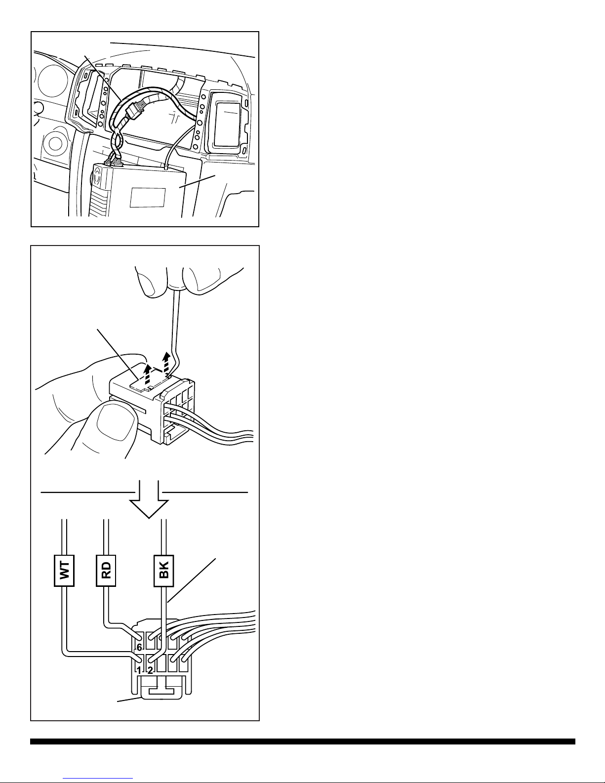
2) Starting at the left (driver’s side) rear door, route
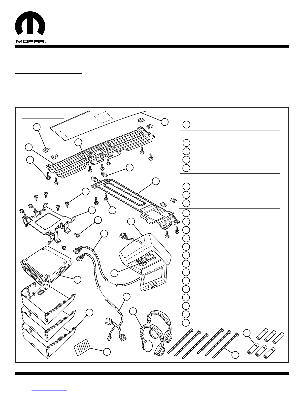
black connector on overhead harness (Item 6)
under headliner and out of trimmed opening.
Leave approximately 4" (101mm) of harness
exposed.
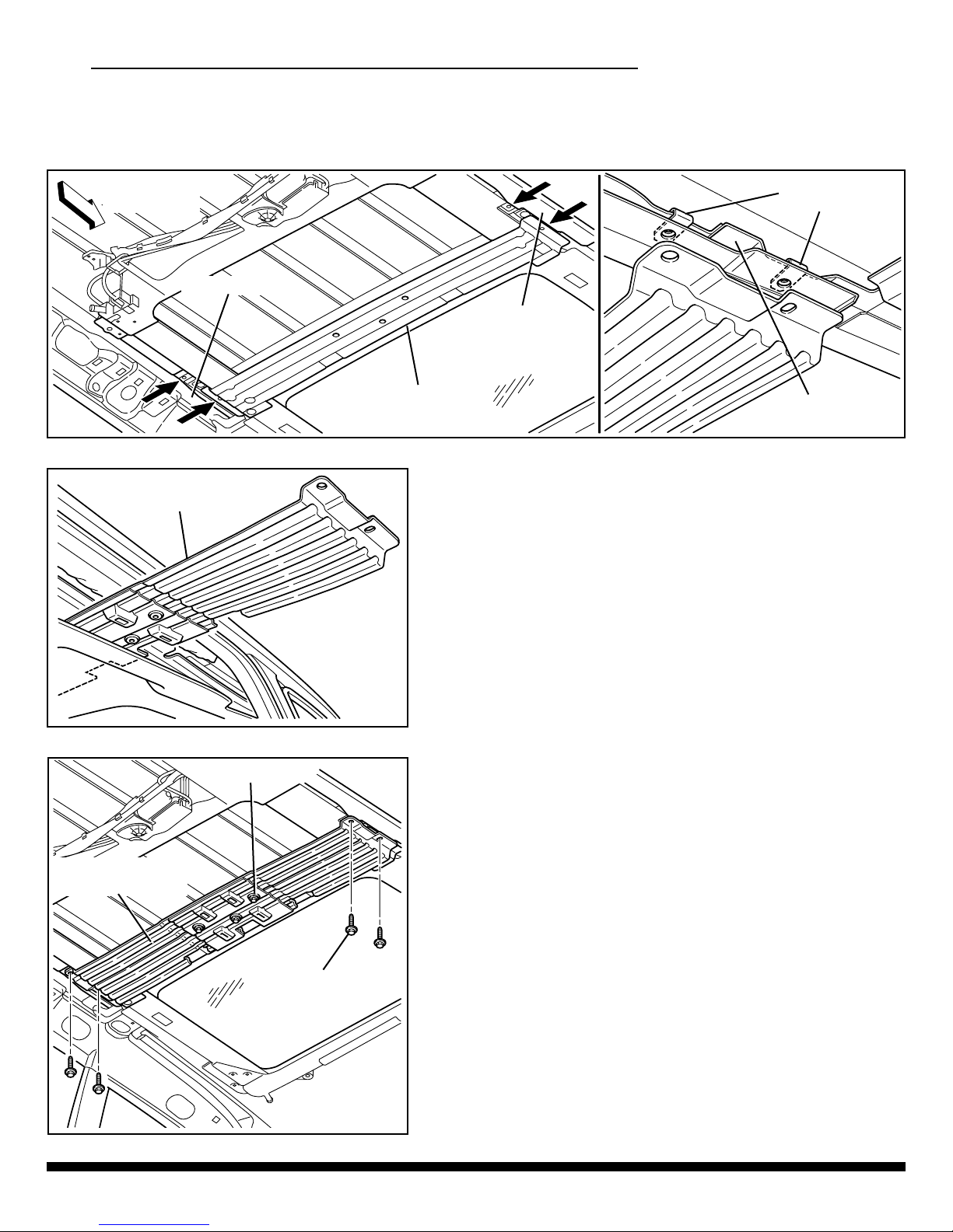
3) Route harness forward along trough in headliner
foam block as shown.
4) Using a a strong adhesive tape, secure harness to
the inside of headliner.
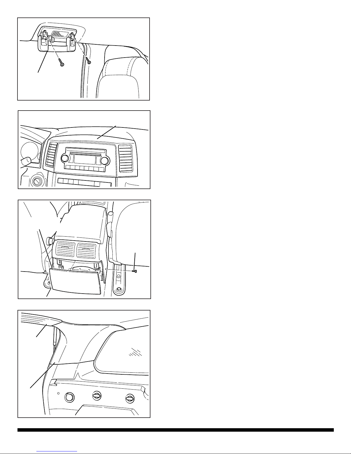
5) At this time the headliner must be positioned back
in place. Re-install all the pillar trim panels, sun
visor/retaining clip, and overhead console.
NOTE: Tighten left and right shoulder belt turning
loop T50 bolts to 29 ft.-lbs. (39 N·m).
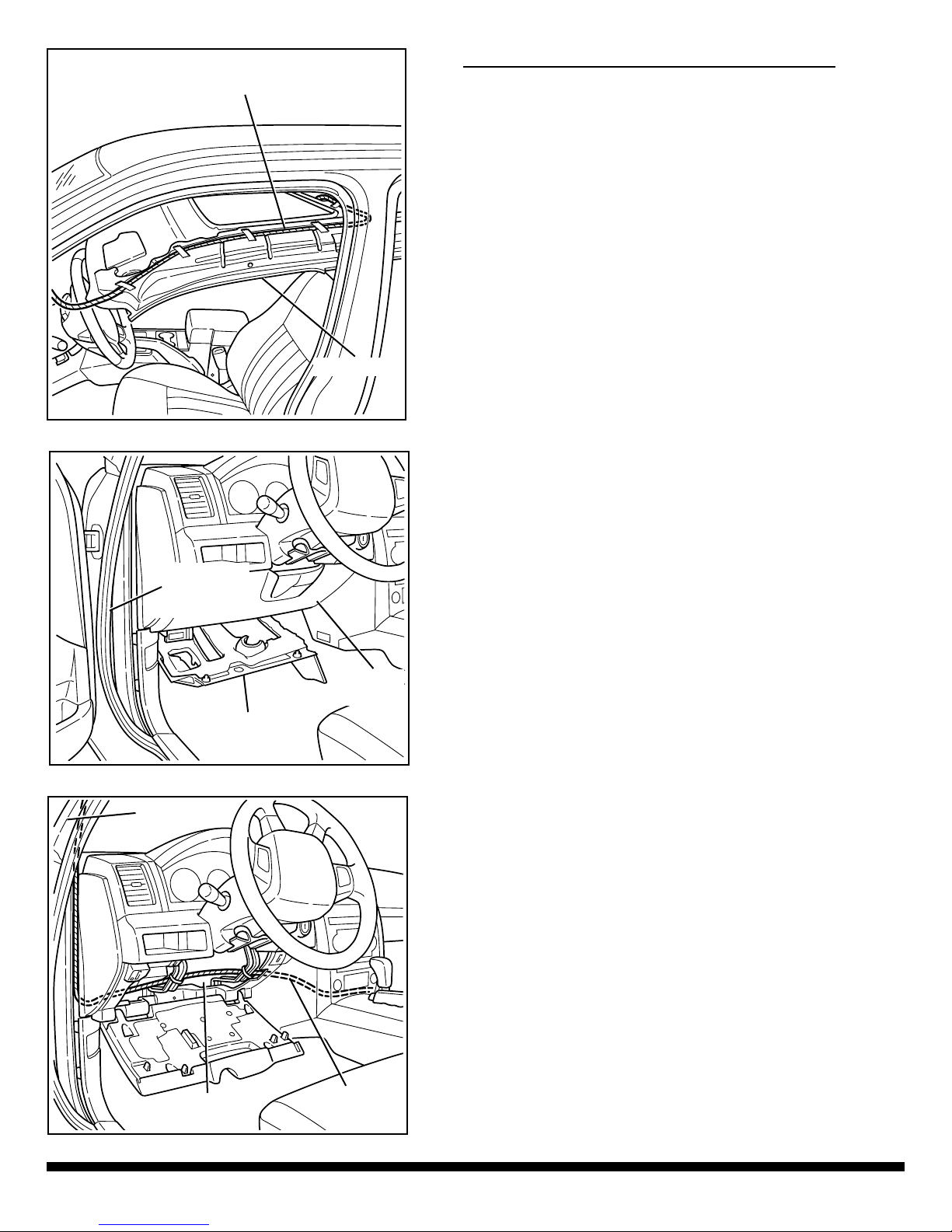
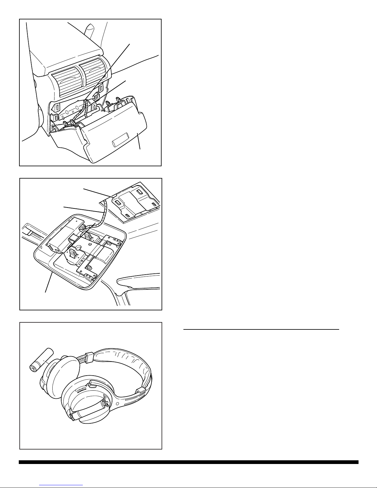
6) Detach left front door weatherstrip from the top of
I/P to the top of door sill.
7) Remove lower I/P closeout panel (two phillips
screws) and drop down the knee blocker.
8) Continue to route overhead harness down the left
A-pillar and secure it to the rear window washer
feed hose using three tie straps (Item 7).
9) Route harness across the inside of knee blocker
opening and through to the lower right center
console trim panel.
NOTE: Secure harness away from any heat sources,
sharp edges, or moving parts.
Left Front
Door
Weatherstrip
Knee
Blocker
Closeout
Panel
Headliner
Knee Blocker
Opening
Overhead
Harness
Left A-Pillar
Overhead
Harness

10) Hand feed 12-way connector on power harness
(Item 8) into radio opening and down the right side
of center console.
11) Plug 22-way connectors in-between the radio and
radio harness connector.
12) Plug 10-way connector into the radio.
NOTE: If there is a 10-way connector already present
in the radio, it means that the vehicle is
equipped with Satellite Radio. Refer to the
following procedure (A-F) and graphic:
K6859241 11/09/2004 Page 7 of 10
a) Unplug 10-way connector from the radio.
b) Using a hooked pick tool lift up the connector
locking wedge slightly (do not remove it entirely).
c) Remove the three wires from connector and
discard it.
d) Lift up the 10-way power harness connector
locking wedge slightly.
e) Insert the three wires into 10-way power harness
connector as shown at left.
f) Engage locking wedge and plug connector into the
radio.
Radio
Power
Harness
Locking Wedge
(Do not remove)
10-Way Satellite
Radio Connector
10-Way
Power Harness
VES Connector
Satellite Radio
Wires (3)

K6859241 11/09/2004 Page 8 of 10
13) Route power harness and overhead harness
rearward behind right side of floor console and
under the carpet liner.
14) Position the harness connectors approximately
6" (152mm) out of the rear console’s end cap
mounting tabs.
15) Bundle up any slack in the harness, tape, and tuck
neatly inside of center console.
NOTE: Make sure the power harness and overhead
harness remain under the carpet liner to
prevent rattles.
E – Install DVD Player and Screen Console:
1) Install bracket (Item 9) to DVD player (Item 10)
with four T25 screws (Item 11).
2) Install bracket/DVD player to the appropriately
colored end cap/lid assembly (Item 12) with four
T15 screws (Item 13).
Overhead
Harness
Power
Harness
Floor
Console
End Cap/Lid
Assembly
Bracket
T25
Screws (4)
T25 Screws (4)
DVD Player

K6859241 11/09/2004 Page 9 of 10
3) Plug 12-way power harness connector and 16-way
overhead harness connector into the back of DVD
player.
4) Fully engage the DVD bracket’s two hook tabs to
the floor console bottom mounting slots.
5) Snap four retaining clips on the DVD bracket into
the floor console mounting slots. Make sure the
harnesses are not pinched or crimped.
F – Finalize Installation and Perform Operation Test:
1) Re-install all previously removed components,
panels, and fasteners.
2) Re-connect the vehicle’s battery.
3) Place supplied batteries (Item 17) into both head-
phones (Item 18) as shown.
4) Place batteries into DVD remote.
6) Plug and lock overhead harness connector into
the screen console (Item 14).
7) Snap four retaining clips on the top of screen con-
sole into the mounting bracket slots.
8) Open the screen and carefully remove the
attached DVD remote (Item 15).
9) Peel and stick mercury warning label (Item 16) to
lower portion of forward facing surface of the left
(driver’s side) B-pillar.
DVD Player
Assembly
Overhead
Harness
Power
Harness
Mounting
Bracket
Screen
Console
Overhead
Harness

K6859241 11/09/2004 Page 10 of 10
5) Turn on ignition and the unit will power up.
6) Use a diagnostic STARSCAN tool so that the Front Control Module (FCM) is reconfigured and
recognizes the Video Entertainment System (VES). Follow the procedure shown below.
7) Insert a known good DVD into the player.
8) Verify function of headphones and DVD remote using supplied Operating Instructions (Item 19).
9) Place Operating Instructions in the vehicle’s glove box.
IN THE INITIAL START UP SCREEN
• PRESS ------- VEHICLE PREPARATION
• TOGGLE DOWN AND HIGHLIGHT -----
PROGRAM NETWORK CONFIGURATION FCM (CGW)
• PRESS ------- START
• PRESS ------- NEXT>
• TOGGLE DOWN AND HIGHLIGHT ------- VES
• PRESS ------- ADD
FOLLOW ON SCREEN PROMPTS
(I.E. CYCLE IGNITION KEY)
• PRESS ------- NEXT>
• PRESS ------- FINISH
Other manuals for DVD REAR SEAT VIDEO SYSTEM
2
Table of contents
Other Mopar Car Video System manuals
Popular Car Video System manuals by other brands

Boss Audio Systems
Boss Audio Systems HIR70UB user manual

Clarion
Clarion CJ7100E Brochure & specs

Blaupunkt
Blaupunkt AMSTERDAM 290 BT Operating and installation instructions

REAL MEDIA SHOP
REAL MEDIA SHOP TAFFIO CLBEN4-5 quick guide

Rosen
Rosen GM1CAMHD quick start guide

NextBase
NextBase NB7-CAR instruction manual