Monteringsanvisning / Installation instruction Rev. 003 - 17-12-20 MA nr 1004145
6 (8)
Mora Tronic Duschpanel
ENGLISH
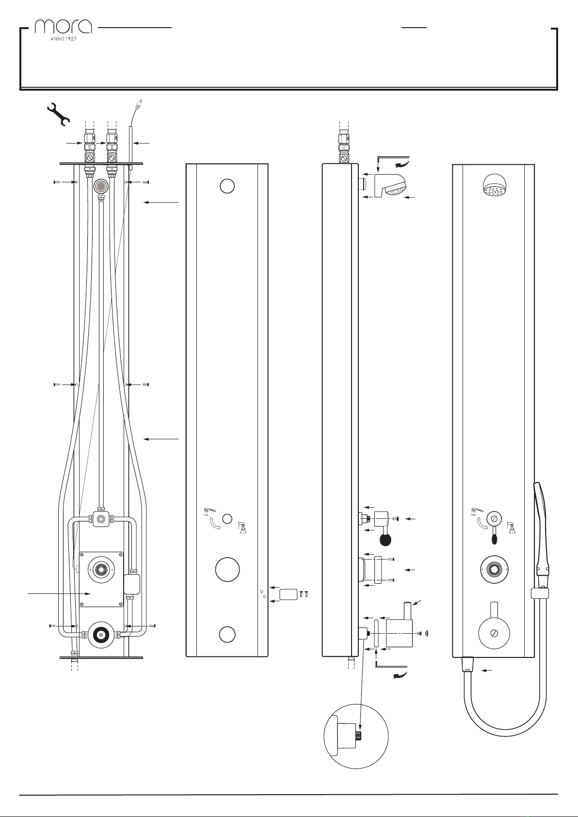
ASSEMBLY
We recommend that you engage a professional (licensed) plumber.
AScrew the wall rail [1] to the wall. Attach the enclosed ball valves [2] and connect the
water supply. Attach the cable gland tube [3] (this does not apply if the assembly is
battery powered). Attach the cover [5]. NOTE! If the assembly includes a hand shower
holder [4], it must be attached before the panel is fixed to the wall rail (attach it from the
inside using 2 screws). Attach the cover [5] to the wall rail [1]. Attach the shower head
[6], press it in firmly and screw it into place. Attach the diverter tube lever [7] and screw
it into place. NOTE! The spindles for the diverter and temperature control knob may not
be moved from their preset positions before the knob/lever has been attached. Attach
the button’s cover ring [8] and screw it into place. Attach the cover ring [9], press it in
firmly and screw it into place. NOTE! If the mixer has an anti-legionella cartridge, con-
nect a stop ring with the marking pointing upwards. Attach the temperature control
knob [9] with the override button upwards and screw it into place. Attach the hand
shower [10] and screw it into place. The panel can be used immediately after complet-
ing the installation (preset shower time 30 s). If operating from the mains, do not touch
the button for 90 sec. after switching on the power. For information about setting the
shower time, see “Changing the shower time”.
NOTE! Some dripping may occur after use.
INSTALLATION
FInstallation, electricity:
Battery operation: 1 x 6LR61 alkaline or lithium battery.
Mains operation: 9V DC stabilised.
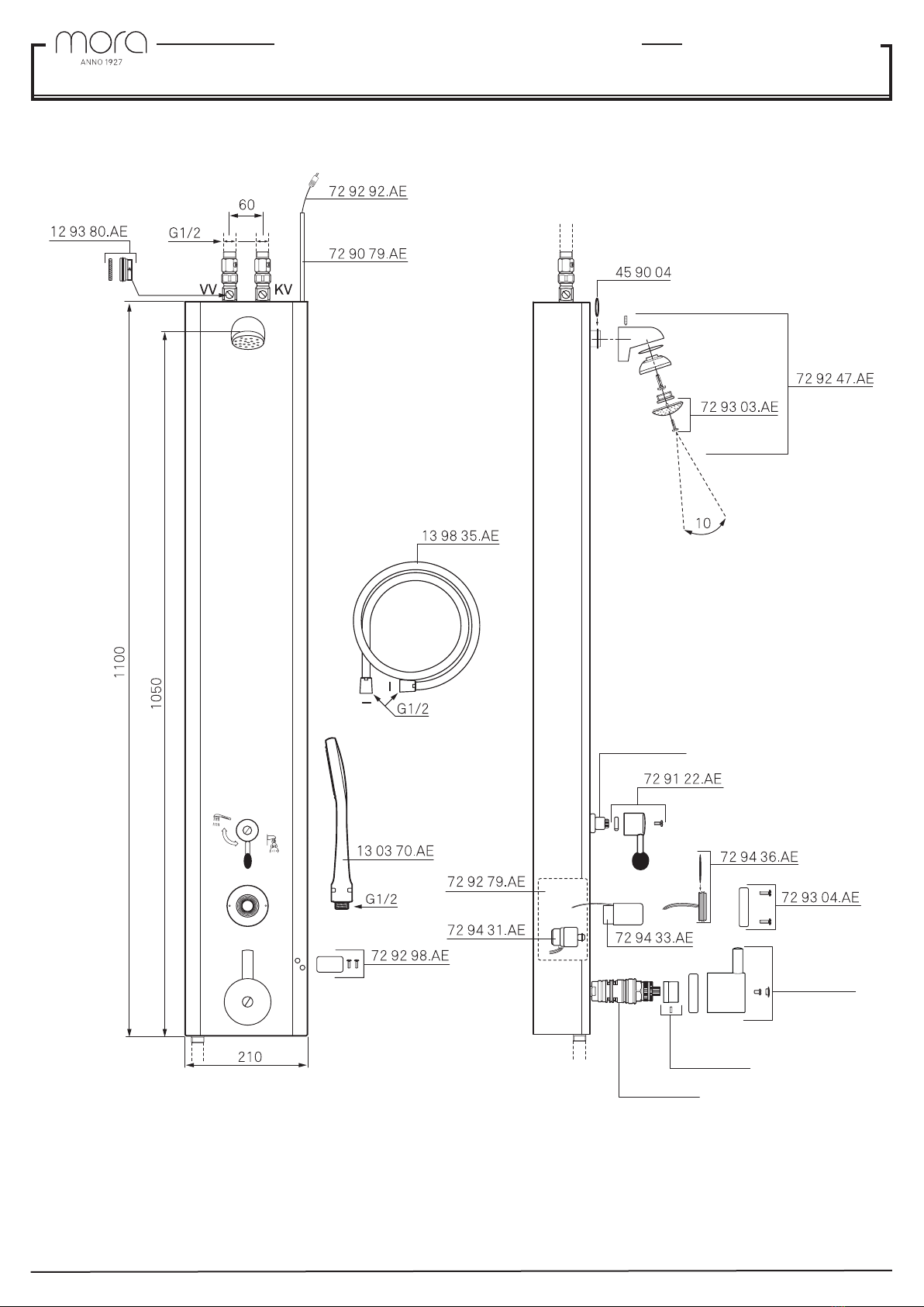
Place the transformer and the distribution box (not included) in a suitable, dry location.
Suitable transformer MA No. 729428.AE.
NOTE! If cables are spliced, take care not to reverse the polarities.
Installation, water:
Max. working pressure: 1.0 MPa.
Min. working pressure: 100 kPa.
Max. temperature: 85 °C
Touch button:
Programmable touch button for 10 –60 s shower time. See “Changing the shower time”.
TROUBLESHOOTING/SERVICE
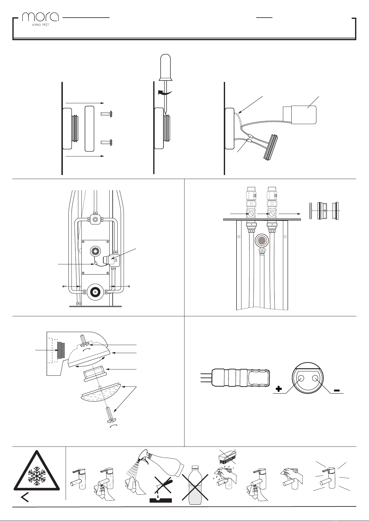
B Changing the battery:
Detach the cover ring from the panel [1]. Disconnect the button [2]. Carefully pull out
the battery holder [3]. Replace the battery, 1 x 6LR61 (a). Grease the button’s O-ring.
Reassemble the parts.
B Changing the shower time (battery operation):
Detach the cover ring from the panel [1]. Disconnect the button [2]. Disconnect and
reconnect the battery power (a). Within one minute after connection, press as many
times as is necessary to set the desired shower time (see below). Do not touch the but-
ton for 90 seconds. Reassemble the parts.
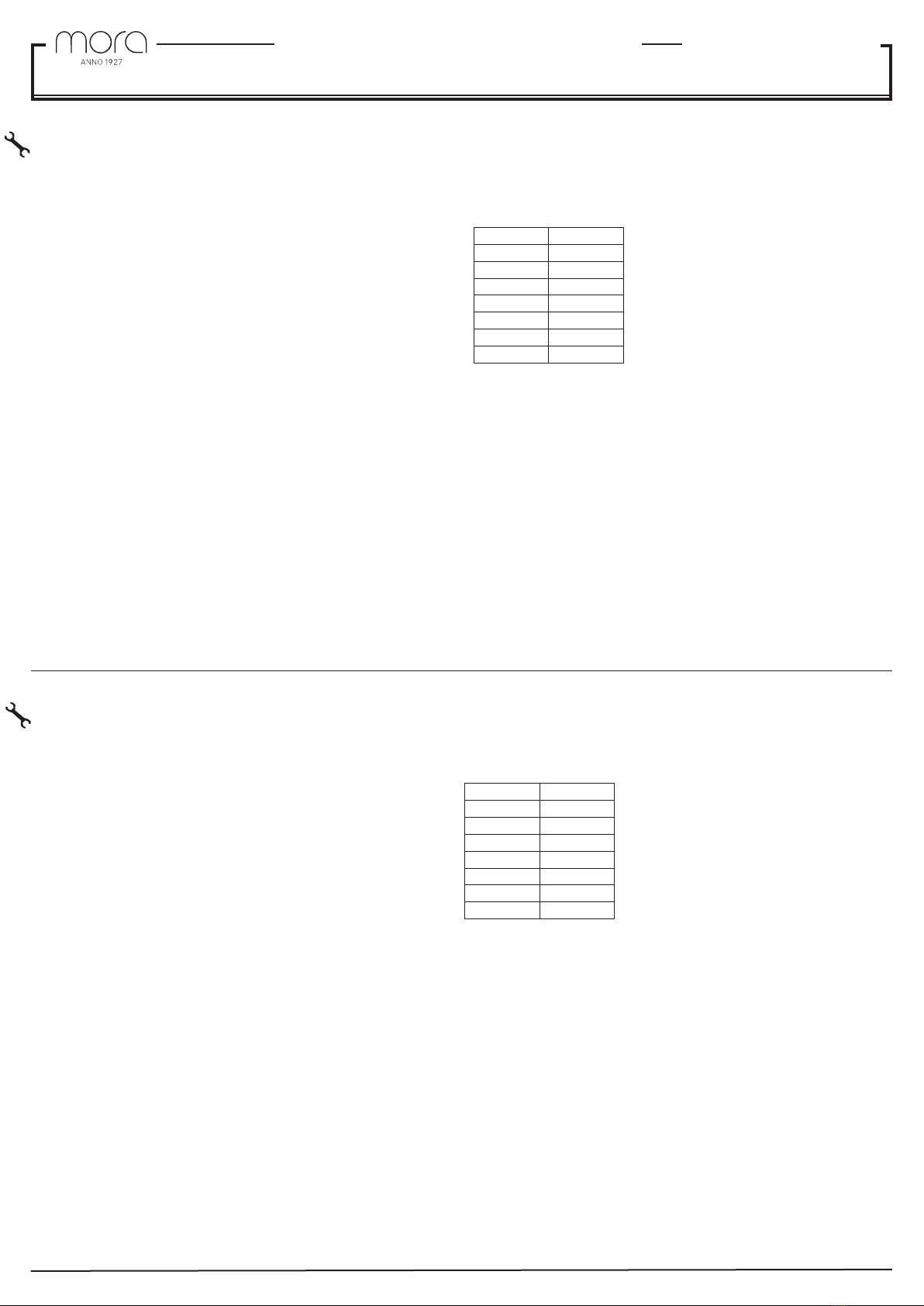
B Changing the shower time (mains operation):
Detach the cover ring from the panel [1]. Disconnect the button [2]. Pull apart the con-
nector between the connected cable and the button (b). Plug together the connectors.
Within one minute after connection, press as many times as is necessary to set the
desired shower time (see below). Do not touch the button for 90 seconds. Reassemble
the parts.
Number of
presses
Shower time
0 30s
1 10
220
3 30
440
5 50
6 60
Calibration of thermostat:
Dismantle the temperature control knob, see fig. A[9]. Turn the spindle clockwise for
cooler water and anti-clockwise for warmer water, see fig. A[12]. When the desired
water temperature has been reached, attach the temperature control knob with the
override button upwards, see fig. A[9].
C Changing the magnetic valve:
Close the ball valves, see fig. A[2]. Dismantle all the outer parts, see fig. A[6-9]. Lift
off the cover, see fig. A[4-5]. Disconnect the lid from the plastic box, see fig. A[11].
Pull apart the connectors between the magnetic valve and the button (a). Unscrew the
magnetic valve (b). Attach a new magnetic valve. Reassemble the parts.
D Cleaning the inlet filter or changing the non-return valves:
Close the ball valves, see fig. A[2]. Prise away the cover (a). Pull out the non-return
valve (c). Clean the strainer (b) or the non-return valve (c). Reassemble the parts.
E Setting the shower angle:
Dismantle the strainer ring (a). Prise away the attachment nipple (b). Unscrew the screw
(c) about 1 turn. Set the strainer holder (d) in the desired position. Tighten the screw (c).
The flow limiter (e) can be removed or replaced as necessary. Reassemble the parts.
GUARANTEE
Original Mora Armatur parts must be used in order for the guarantee to be valid.
End-of-life products may be returned to Mora Armatur for recycling.
DEUTSCH
MONTAGE
Wir empfehlen, einen professionellen HLS-Installateur zu beauftragen.
AVerschrauben Sie die Wandschiene [1] an der Wand. Montieren Sie die beiliegenden
Kugelventile [2] und verbinden Sie den Wasseranschluss. Montieren Sie das Rohr für
die Kabeldurchführung [3]. Dies gilt nicht bei einem Batteriebetrieb. Montieren Sie das
Abdeckblech [5]. Hinweis: Eine eventuelle Handduschenhalterung [4] muss vor der
Anbringung der Konsole an der Wandschiene montiert werden. (Die Montage erfolgt mit
2 Schrauben von der Innenseite.) Montieren Sie das Abdeckblech [5] an der Wandschie-
ne [1]. Montieren Sie den Duschkopf [6], drücken Sie ihn fest hinein und schrauben Sie
ihn fest. Bringen Sie den Mischerhebel [7] an und schrauben Sie ihn fest. Hinweis: Die
Voreinstellungen der Spindeln für Mischer und Temperaturregelung dürfen erst nach der
Montage von Rad/Hebel geändert werden. Montieren Sie den Abdeckring des Tasters [8]
und schrauben Sie ihn fest. Montieren Sie den Abdeckring [9], drücken Sie ihn fest hinein
und schrauben Sie ihn fest.
Hinweis: Mit Legionelleneinsatz. Der Stoppring wird mit der Markierung nach oben
montiert. Montieren Sie das Temperaturregelungsrad [9] mit nach oben weisender
Sperrtaste und schrauben Sie es fest. Montieren Sie die Handdusche [10] und schrauben
Sie sie fest. Nach abgeschlossener Montage kann die Konsole sofort genutzt werden
(voreingest. Duschzeit = 30 s). Betätigen Sie bei Netzbetrieb den Taster frühestens 1,5
min nach Einschalten der Netzstromversorgung. Hinweise zum Anpassen der Duschzeit
entnehmen Sie dem Abschnitt „Duschzeit ändern“.
Hinweis: Nachträglich kann noch eine geringe Wassermenge austreten.
INSTALLATION
FElektrische Installation:
Batteriebetrieb: 1 x 6LR61, Alkali oder Lithium.
Netzbetrieb: 9 V GS stabilisiert.
NetzteilundVerteilerkastensindaneinergeeignetentrockenenPositionzuverwahren(nicht
im Lieferumfang enthalten). Passender netzteil MA-Nr. 729428.AE.
Hinweis: Bei einer eventuellen Kabelverbindung ist auf die korrekte Polarität zu achten.
Wasserinstallation:
Max. Betriebsdruck: 1,0 MPa.
Min. Betriebsdruck: 100 kPa.
Max. Temperatur: 85°C
Taster:
Programmierbarer Taster für 10–60 s Duschzeit. Siehe Abschnitt „Duschzeit ändern“.
FEHLERSUCHE/SERVICE
B Batteriewechsel:
Lösen Sie den Abdeckring von der Konsole [1]. Demontieren Sie den Taster [2]. Ziehen
Sie vorsichtig die Batteriehalterung [3] heraus. Wechseln Sie die Batterie: 1 x 6LR61 (a).
Fetten Sie den O-Ring des Tasters ein. Montieren Sie die Komponenten erneut.
B Duschzeit ändern (Batteriebetrieb):
Lösen Sie den Abdeckring von der Konsole [1]. Demontieren Sie den Taster [2]. Unterbre-
chen und schließen Sie die Batterieverbindung (a). Führen Sie innerhalb von 1 min nach
dem Verbinden die erforderliche Anzahl von Betätigungen für die gewünschte Duschzeit
aus (siehe unten). Berühren Sie den Taster frühestens nach 1,5 min. Montieren Sie die
Komponenten erneut.
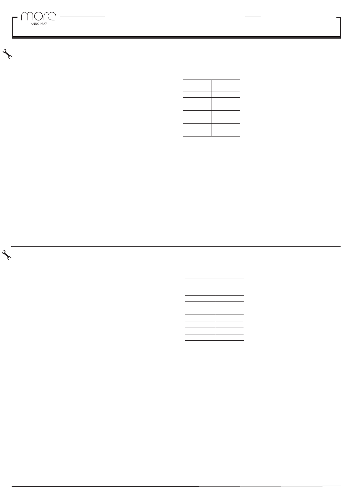
B Duschzeit ändern (Netzbetrieb):
Lösen Sie den Abdeckring von der Konsole [1]. Demontieren Sie den Taster (2). Lösen
Sie die Verbindung zwischen angeschlossenem Kabel und Taster (b). Verbinden Sie die
Kontakte. Führen Sie innerhalb von 1 min nach dem Verbinden die erforderliche Anzahl
von Betätigungen für die gewünschte Duschzeit aus (siehe unten).
Berühren Sie den Taster frühestens nach 1,5 min. Montieren Sie die Komponenten erneut.
Anzahl der
Betätigun-
gen
Duschzeit
0 30s
1 10
220
3 30
440
5 50
6 60
Thermostat kalibrieren:
Demontieren Sie das Temperaturregelungsrad, siehe Abbildung A[9]. Drehen Sie die
Spindel für kälteres Wasser im Uhrzeigersinn und für wärmeres Wasser gegen den Uhr-
zeigersinn, siehe Abbildung A[12]. Nach Festlegung der gewünschten Temperatur ist
das Temperaturregelungsrad mit der Sperrtaste nach oben zu montieren,
siehe Abbildung A[9].
C Magnetventil ersetzen:
Schließen Sie die Kugelventile gemäß Abbildung A[2]. Demontieren Sie alle externen
Komponenten, siehe Abbildung A[4-5]. Heben Sie das Abdeckblech ab, siehe Abbildung
A[11]. Demontieren Sie den Verschluss der Kunststoffabdeckung, siehe Abbildung A
[11]. Lösen Sie die Verbindung zwischen Magnetventil und Taster (a). Schrauben Sie
das Magnetventil (b) heraus. Bringen Sie ein neues Magnetventil an. Montieren Sie die
Komponenten erneut.
D Eintrittsfilter reinigen bzw. Rückschlagventile ersetzen:
Schließen Sie die Kugelventile gemäß Abbildung A[2]. Lösen Sie den Verschlussdeckel
(a). Ziehen Sie das Rückschlagventil (c) heraus. Reinigen Sie das Sieb (b) bzw. Rück-
schlagventil (c). Montieren Sie die Komponenten erneut.
E Duschwinkel einstellen:
Demontieren Sie den Siebring (a). Lösen Sie den Befestigungsnippel (b). Lösen Sie die
Schraube (c) um etwa eine Umdrehung. Bringen Sie die Siebhalterung (d) in die ge-
wünschte Stellung. Ziehen Sie die Schraube (c) an. Der Durchflussbegrenzer (e) kann bei
Bedarf entfernt oder gewechselt werden. Montieren Sie die Komponenten erneut.
GARANTIE
Für die etwaige Inanspruchnahme einer Garantie müssen Mora Armatur-Originalkompo-
nenten verwendet werden.
Altprodukte können zu Recyclingzwecken Mora Armatur zugeführt werden.