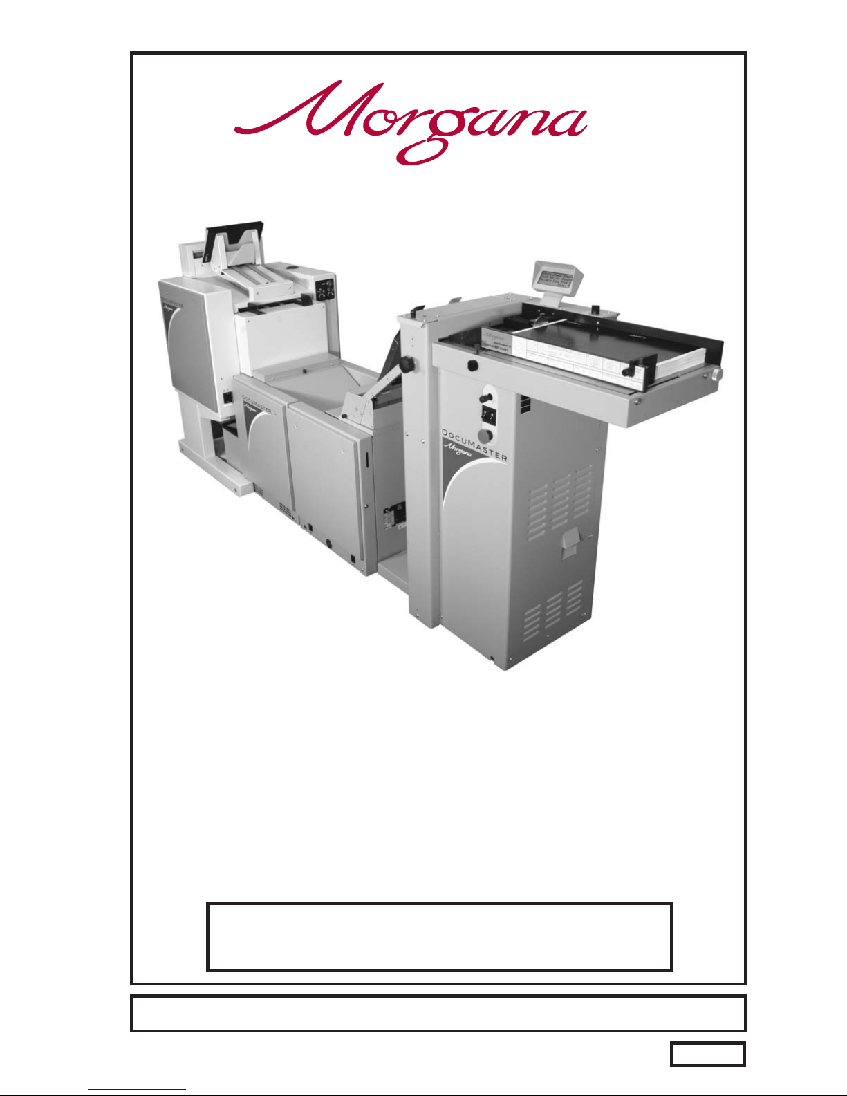
Morgana Documaster MK3 User manual

ISSUE 8 JULY
2009
DOCUMENT CREASING & AUTOMATIC
BOOKLET MAKING MACHINE
(Creasing Unit)
OPERATORS MANUAL (Part 1)
FROM SERIAL No. 780156 ONWARDS.
Documaster MK3
Website: www.morgana.co.uk
70-111
Morgana Systems Limited United Kingdom
Telephone: ( 01908 ) 608888 Facsimile: ( 01908 ) 692399

Page 2
INDEX
CREASING / BOOKLET MAKING
SAFETY Do’s & Don’ts 6
THE CREASING UNIT 9
THE CONTROL PANEL 10
11
SETTING THE MACHINE UP AS A CREASER 12
12
13
13
13
13
13
13
15
17
17
18
18
19
20
20
20
20
SETTING THE MACHINE UP AS A BOOKLET MAKER 22
22
23
24
24
25
25
25
26
26
28
28
29
30
31
Labelled Photograph
Detailed diagram and description
Features on the control panel
Adjusting the Paper Gate
Setting the Suction Slot
Setting the Vacuum Bleed
Setting the Adjustable Side Lay
Setting the Back Stop
Setting the Air Seperation Pressure
Setting the Roller Tilt Mechanism
Setting the position of the Drive Wheels and Hubs
Setting the Stacker Assembly
Programming the machine for Creaser Operation
Setting the Feed
Setting the Batch Quantity
Setting the Crease Positions
Storing the Crease Positions
Running the machine
Reading Stored Programs
Paper Jamming
Setting the Machine to Run in Manual Mode
Adjusting the Paper Guides
Adjusting the Sliding Back Stop
Programming the machine for Booklet Maker Operation
Setting the Feed
Setting the Page Length
Setting the Book Centre
Setting the Sheet Width
Setting the number of Sheets in the Book
Setting the Crease Style
Setting the Cover Crease
Setting the Stitch Position
Setting the Machine to Edge Stitch
Setting the Set Knock
Setting the Trimmer
Setting the Batch Quantity
Setting the Air Distribution 13
INTRODUCTION PAGE 4The Morgana Documaster Mk3

Page 3
SYSTEM
INDEX
31
31
32
32
33
34
37
PERFORATING 39
40
THE BLADE ASSEMBLY 42
43
REPLACING CREASING BLADE SETS 44
45
TROUBLE SHOOTING 46
ERROR MESSAGES 49
DISPATCH KIT 50
ACCESSORIES AND OPTIONS 51
RECOMMENDED SPARES 52
MACHINE CALIBRATION HISTORY 54
PRODUCT RECYCLING & DISPOSAL 55
Storing the Program
Running the Machine
Reading Stored Programs
Clearing Booklet Sheets from the Booklet Maker Infeed Tray
Using the Booklet Maker in Manual Mode (Hand Feed)
Using the Optional Camera Recognition System (Fixed Data)
Using the Optional Camera Recognition System (Variable Data)
Equipment, spares
Setting the machine
Setting the blade pressure
Setting the blade alignment
Installing new blade sets
Spares
DocuMaster MK3

Page 4 CREASING / BOOKLET MAKING
INTRODUCTION
The crease is programmed from the leading edge of the sheet using the
controls on the front panel.
The blade and anvil are mechanically controlled over their entire length
and can be adjusted to accommodate various weights of media
.
Maximum sheet size:- 630mm x 330mm (24.8” x 13”)
Minimum sheet size:- 210mm x 140mm (8.27” x 5.5”)
Maximum sheet weight:- 400 gsm
Minimum sheet weight:- 80 gsm (160 gsm when creasing and folding).
Maximum number of creases:- Nine
Minimum distance between creases:- 4.0mm
Minimum incremental adjustment:- 0.1mm
Minimum crease distance from leading edge:- 30.0mm (1.2”)
Minimum crease distance from trailing edge:- 30.0mm (1.2”)
Production up to 5000 sheets / hour, (one crease on A4 sheet).
CREASER UNIT SPECIFICATION
The Morgana DocuMaster MK3 is a fully automatic, suction feeding, creasing
/ booklet making system; designed for use with both conventional litho and
digital printers.
the operating environment should be controlled to a temperature
between 10
The system comprises a creasing unit linked to a fully automatic booklet
making machine, the creasing unit and booklet maker can be used
separately to give optimum flexibility.
The feed system incorporates an ultrasonic detector system to ensure
complete booklet integrity.
The feed on the Documaster MK3 can also be manually operated for use with
heavy stock, very small or very large sheets, embossed or even irregular
sheets.
IMPORTANT
°°C and 30 C and at 35 - 85% relative humidity.
DocuMaster MK3

Page 5
SYSTEM
BOOKLET MAKER UNIT SPECIFICATION
Maximum sheet size:- 460mm x 320mm (18.1” x 12.6”)
Minimum sheet size:- 210mm x 140mm (8.27” x 5.5”)
Maximum staple pitch:- 138mm (5.4”)
Minimum staple pitch:- 115mm (4.5”)
Maximum number of sheets in book:- 20 sheets (80 gsm)
Maximum cover weight :- up to 350 gsm
Minimum inside sheet weight:- 80 gsm
Maximum trim:- 25mm (1”)
For optimum performance the difference between the cover and the
inside sheet should be no more than 110 gsm.
Production up to 1560 books / hour, (dependant on number of sheets in book).
DocuMaster MK3

Page 6 CREASING / BOOKLET MAKING
Safety Do’s & Don’ts
Do - read this operator manual fully before operating the machine.
Do - operate with the designated AC current only. Use an exclusive outlet, as
overloading may cause fire or an electric shock.
Do - install the power cord out of the way to avoid a tripping hazard.
Do - make sure that the mains inlet connector is always easily accessible.
Do not - install the machine in an unstable place such that it tilts or shakes.
Do not - unplug the plug or unplug the power cord from the outlet with a wet hand,
this can cause an electric shock.
Do not - unscrew and remove any covers from the machine, as it can cause an
electric shock or injury.
Do not - place receptacles containing liquids on any surface.
Do not - adjust any part of the machine whilst rollers are running
Do not - operate the machine with loose or trailing clothing or loose hair.
Do not - under any circumstances adjust the paper gate when the machine is
switched on.
REGLES DE SECURITE : « A FAIRE » ET « A NE PAS FAIRE »
Lire ce mode d'emploi avant d'utiliser la machine.
Respecter l'alimentation électrique indiquée. Brancher sur une prise séparée
car une surcharge peut entraîner un incendie ou un choc électrique.
Installer le cordon d'alimentation de manière à ne pas pouvoir
trébucher par dessus.
Ménager un accès libre à la prise de courant.
Ne pas installer la machine sur une surface non plane, afin d'éviter
qu'elle ne penche ou ne vibre.
Ne pas installer la machine sur une surface non plane, afin d'éviter
qu'elle ne penche ou ne vibre.
Ne démonter et enlever aucun carter de la machine, par crainte de décharge
électrique ou de blessure.
Ne pas placer de récipient contenant un liquide sur la machine.
N'effectuer aucun réglage pendant que les rouleaux fonctionnent.
Ne pas porter de vêtements flottants et rassembler les cheveux longs
lors de l'utilisation de la machine.
En aucune circonstance, régler le séparateur de papier lorsque la
machine est branchée.

Safety Do’s & Don’ts
Page 7
SYSTEM
Warning Labels
Do - be aware of any finger traps and rotating parts when operating
the machine.
Do - read this operator manual fully before operating the machine.
Do not - operate the machine with loose or trailing clothing.
Do not - operate the machine with loose hair.
Do - be aware of any finger traps and rotating parts when operating
the machine.
Do - be aware of sharp points and blades.
Do - be aware of rotating rollers.
Do - be aware of low current anti-static shock.
Attention au risque de se coincer les doigts, et aux pièces en
mouvement lors du fonctionnement de la machine.
Ne pas porter de vêtements flottants lors de l'utilisation de la machine
Rassembler les cheveux longs lors de l'utilisation de la machine.
Attention au risque de se coincer les doigts, et aux pièces en
mouvement lors du fonctionnement de la machine.
Attention aux éléments tranchants et aux couteaux.
Attention aux rouleaux en fonctionnement
Attention aux faibles chocs d'électricité statique
Lire ce mode d’emploi avant d’utiliser la machine.
DocuMaster MK3

Page 8 CREASING / BOOKLET MAKING
BLANK
PAGE

Page 9
SYSTEM
THE CREASING UNIT
5
2115 12 11 69
14
8
7
4
3
10
13
Key to photograph below
1 Roller tilt handle 6 Air separation knob 11 Paper Gate
2 Stacker assembly 7 Adjustable side lay 12 Exit Guard
3 Suction slot knob 8 Back stop 13 Vacuum Bleed Knob
4 The control panel 9 Fixed side lay 14 Display
5 Air distribution knob 10 Roller tilt knob 15 Anti-Static Unit
DocuMaster MK3
DocuMaster MK3

Page10 CREASING/BOOKLETMAKING
THECONTROLPANEL
SystemSwitch
CompressorSwitch
EmergencyStopSwitch
SelectionSwitch
THECONTROLS
TheDisplayUnitandtheSwitchesontheControlPanelallowthe
operatortoread,edit,createandinitiatenumerouscreasingprogramswithin
thememory.
TheControlPanelhousestheSelectionSwitch,Compressorswitch,
Systemswitch,andanindustrystandardEmergencyStopswitchwhich
willstopallpowergoingtothemachinewhenactivated.

Page 11
THE CONTROLS
SYSTEM
Features on the Control Panel
Selection Switch
System switch
Compressor switch
Allows the operator to scroll through stored addresses and programs, increase or
decrease the batch quantity and set a crease position.
When activated the system switch will operate the motors in order to begin the
creasing sequence.
Allows the operator to switch off the compressor unit in order to utilise the machine
to manually feed sheets.
DocuMaster MK3

Page 12
Adjustable
Side Lay
J
K
6.5mm (1/4")
TWO THICKNESSES
OF PAPER
Suction
Slot Knob
IMPORTANT:-
To avoid possible damage to the suction drum,
when adjusting the paper gate height, ensure that
drum and not over a slot in the drum.
the disc is located over a solid section of the suction
Do not adjust the paper gate while the machine is
running.
CREASING / BOOKLET MAKING
Vacuum
Bleed Knob
Setting the Machine up as a Creaser
Adjusting the Paper Gate
The standard setting for horizontal adjustment of the paper gate is 6.5mm (1/4") away
from the mounting block. Turn disc J to make this adjustment. This setting is only intended
as a guide, for instance, sheets with an upward curl will require this setting to be in-
creased. Set the height of the Paper Gate to approximately two thicknesses of paper, by
turning knob K. An excessive gap is a most likely cause of double sheet feeding.
Setting the Suction Slot
The suction slot is located inside the vacuum roller and can be adjusted by releasing and
moving the suction knob horizontally in either direction to the required position.
For light stocks set the knob to the left and for heavier stocks set the knob to the right.
FIG 8.2
FIG 8.1

Page 13
SYSTEM
Setting the Machine up as a Creaser
Setting the Vacuum Bleed
Setting the Adjustable Side Lay
Setting the Back Stop
Setting the Air Distribution
Setting the Air Separation Pressure
Place the paper stack on to the loading table and slide up to the fixed side lay and paper
Gate. Release the clamps located at each end of the side lay and slide up towards the
paper stack as demonstrated in FIG 8.1. Allow a gap of approximately 0.5mm (1/64 inch)
between the paper and the side lay.
When using heavy stocks or large paper stacks, the feeding of the sheets may be improved
by fitting the Clamp Plates to the Adjustable Side Lay, as shown in FIG 8.2 below; but
please be aware that they may cause double feeding when using light stocks.
Position the backstop and slide up towards the paper stack allowing a gap (as specified
in the above step).
Depending on the length of the sheet to be creased, the air distribution knob can be
rotated to various positions in order to supply air to different ports. Position 1 is
recommended for most sheet sizes. However, a better result may be obtained by using
the settings below or by experimentation.
For A5 sheets or 8 inches long, front port and port 1 open.
For A4 sheets or 11 inches long, front port and port 2 open.
For A3 sheets or 17 inches long, front port and port 3 open.
For longer sheets in order to supply air to the centre of the stack, port
1 and port 2 open.
To control the amount of air supplied to the ports, the air separation knob can be adjusted
by first rotating the knob to unlock its position, then push the knob down to the required
position and rotate the knob to re-lock its position.
NOTE.
Position 1 -
2-
3-
0-
Situated on the front of the feed table, the Vacuum Bleed Knob is used to allow more
control of the suction on the vacuum drum.
When light weight paper of 90gsm and lower is being fed through the machine turn the knob
clockwise to reduce the possibility of marking, or damage to the leading edge of the paper.
FIG 8.2 Clamp Plates
FIG 8.1
DocuMaster MK3

Page 14
FIG 10.1
CREASING / BOOKLET MAKING
Setting the Machine up as a Creaser
FIG 13.1
Setting the Roller Tilt Mechanism
Setting the positions of drive wheels and hubs
The roller tilt mechanism has been designed to compensate for when the creasing
position on the sheet is not square. This could be due to an inaccuracy in the media or if
the roller tilt mechanism has been incorrectly set. The mechanism will be set to zero
(square) when the machine is supplied.
To set the mechanism, unlock the roller tilt knob located below the roller tilting handle by
turning anti- clockwise. Move the roller tilt handle left or right in order to compensate for
any inaccuracy. When the position is set, ensure to lock the roller tilt knob before
operating the machine. Repeat the above procedure until the creasing position is square.
It is important that the drive wheels and drive hubs on the roller shafts are arranged evenly
across the width of the media being creased. This is done to ensure that the media is
accurately driven and supported through the rollers.
The drive wheels and hubs are fixed to the rollers by means of a grub screw. To locate
this grub screw the rollers can be rotated by operating the motor manually.
To operate the motors manually, switch the machine ‘on’ at the Emergency Stop switch.
Following the arrows on the display unit, move the selection switch to the left to select
, the display will now show the Tools sub-menu. Press the system switch down and
then move the selection switch to the left or to the right, to rotate the rollers in short pulses.
Lift the exit guard to see if the grub screws in the drive wheels and hubs can be seen. If the
grub screws cannot be seen, lower the exit guard and rotate the rollers by moving the
selection switch to the left or to the right. Loosen the drive wheels and hubs with a 2mm
allen key. Arrange the drive wheels and hubs as shown in FIG 10.1. In order to avoid
marking on some types of media ensure a gap between the drive wheels and hubs.
This procedure should be repeated when installing perforating blades and anvils onto the
drive wheels and hubs.
DO NOT ROTATE THE DRIVE ROLLERS BY HAND
.
Tools

Page 15
SYSTEM
Setting the Machine up as a Creaser
LEFT HAND
SIDE GUIDE
FIG 13.1
RIGHT HAND
SIDE GUIDE
LEFT HAND
BACK STOP
RIGHT HAND
BACK STOP
Setting the Stacker assembly
The stacker unit on the machine is used to catch the sheets once they have been
creased or perforated.
NOTE:- This stacker unit is not fitted when the machine is being used as a Booklet maker.
1. Assemble the stacker unit to the machine as shown in fig 13.1 below.
There are two side guides on the stacker unit; a left handed guide and a right handed
guide. The guides will control the way in which the paper is collated by setting their
positions on the stacker bed.
2. Place a single sheet (from the stack to be creased / perforated) on to the stacker bed
against the ‘left hand’ guide.
3. Position the ‘right hand’ side guide on to the stacker bed leaving a minimum
clearance of approximately 1mm each side of the sheet.
Important
Ensure that the stacker unit has been assembled to the machine properly. However,
if it has not, the connection on the magnetic switch will be broken and the machine
will not operate (see Trouble shooting pages for details).
DocuMaster MK3

Page 16 CREASING / BOOKLET MAKING
Setting the Machine up as a Creaser
4. Whilst the sheet is between the two guides on the stacker bed, set the distance .
between the top of the sheet and the backstop flanges to approximately 5mm.
5. For shorter sheets, the back stop can be used (as shown in FIG 13.1 to adjust the
position of the paper stack.
TIPS
!The magnetic back stop supplied with the machine
can also be used as a tool holder as demonstrated
In the photograph (left).

Page 17
SYSTEM
Setting the Machine up as a Creaser
1 Creases Program 1
Total 20
Reset
Setup
Tools Feed
Batch Off
Autocreaser
Operate This Machine
No
Yes
Are You Trained To
2. If the text on the display contains the word the machine is in the
Booklet Maker mode of operation.
To change to the Creaser mode of operation proceed as follows:-
(i) Move the selection switch up to select .
(ii) Move the selection switch down to .
(iii) Move the selection switch to the right to select .
3. The length of suction on the sheet of paper being fed can be adjusted by setting the
feed type as follows:-
(i) Move the selection switch to the right to select .
(ii) Move the selection switch down to select the required feed type ( ,
, , or )
(iii) Move the selection switch to the right to select .
‘Book’
Set Feed
Reset
Mode to Autocreaser
Mode to Autocreaser
Setup
Long Pulse
Medium Pulse Short Pulse Stream Feed
Select
A typical Autocreaser display menu is shown below.
IMPORTANT.
Programming the machine for Creaser operation
1. Switch the power ‘on’ by turning the Emergency stop button clockwise to release the
safety latch. The display is now switched on and will be as shown below.
If you have not been trained to operate this machine, we strongly advise that you move the
selection switch to the right to select . We recommend that you either seek training or
ask a trained operator to run the machine for you.
Move the selection switch to the left to select only if you have been trained to operate
this machine. If you have not been trained to operate this machine and you select ,
Morgana Systems Ltd accept no responsibility for personal injury, damage to the
machine or damage to materials being processed by the machine.
No
Yes
Yes
MORGANA
DocuMaster MK3

Page 18 CREASING / BOOKLET MAKING
Setting the Machine up as a Creaser
0 Creases Program 3
Total 20
Reset
Setup
Tools Feed
Batch Off
Autocreaser
2nd Crease 0.0
1st Crease 297.0
Home
More
Set Creases
Use for all standard size sheets, general purpose.
Use for short non-standard sheets.
Use for very short sheets.
Use for high throughput, see note below.
Do not use stream feed for creases less than 32mm from the leading edge of the paper.
4. (ii) Move the selection switch to the right to select .
(iii) Move the selection switch down to select .
(iv) Rotate the selection switch clockwise or anti-clockwise to adjust the batch quantity
in increments of 5.
5. Move the selection switch up, one click at a time, until the start up menu is displayed,
(A typical start up display menu is shown below).
(i) Move the selection switch to the right to select .
(ii) Move the selection switch to the right, one click at a time, selecting ;
until the display shows as shown below.
(iii) Following the arrows on the display unit; move the selection switch down to set the
creases. The 1st Crease is now selected.
Long Pulse
Medium Pulse
Short Pulse
Stream Feed
More
Batch Quantity
Setup
More
Set Creases
NOTE.
Setting the batch quantity
Setting the crease positions
NOTE:-
The arrows on the display denote the direction in which the selection
switch must be moved in order to access the various sub-menus.

Page 19
SYSTEM
Setting the Machine up as a Creaser
Back
Tens Decimals
2nd Crease 0.0
( 1st Crease 297.0 )
Set Creases
Back
Tens Decimals
3rd Crease 0.0
( 2nd Crease 0.0 )
Set Creases
Batch 20 Total 80
No Program
Reset
Setup
Tools Feed
2 Creases
Autocreaser
(iv) Move the selection switch to the left to select Tens, or to the right to select Decimals.
(v) The Tens or Decimals (whichever has been selected) can then be adjusted by
rotating the Selection Switch, (clockwise to increase or anti-clockwise to decrease).
(vi) Adjust all other digits for the 1st Crease position as described in steps (iv) and (v),
(i.e. move the selection switch to the left to select the Tens or to the right to select
Decimals and then rotate the Selection Switch to adjust its value.
(vii) To set the 2nd Crease position move the selection switch down; the 2nd crease is
selected and can be set as described in steps (iv) to (vi) above.
Crease positions can be set in increments of 0.1mm. Further creases can be set in
this way, up to a maximum of nine creases.
(viii) When the required creases have been set, move the selection switch up, one click
at a time, until the display contains the word , see below.
6. Once the crease positions are correctly entered, they can be stored as follows.
(i) Move the selection switch to the right to select .
(ii) Move the selection switch to the right, one click at a time, (selecting ) until the
display contains the word .
(iii) Move the selection switch down to select
(iv) Rotate the Selection Switch to select the Program number (1 to 9).
(v) Move the selection switch to the right to select .
(vi) Move the selection switch to the left to select or to the right to select
Feed
Setup
More
Programs
Save Settings.
Select
Yes No.
Storing the crease positions
DocuMaster MK3

Page 20 CREASING / BOOKLET MAKING
Setting the Machine up as a Creaser
Running the machine
In order to manually feed sheets see instructions below.
Reading stored programs
Paper jamming
Setting the machine to operate in manual mode
7. To run the job with the selected settings.
(i) Press the Compressor Switch down.
(ii) Press the System Switch down.
(iii) Move the selection switch down to begin feeding the sheets.
To stop feeding the media at anytime during the program, flick the selection switch up.
The machine will complete its creasing operation if a sheet has already been fed
through the paper gate.
Any of the nine stored programs can be accessed and read as follows:-
(i) From the start up menu, move the selection switch to the right to select .
(ii) Move the selection switch to the right, one click at a time, until the display contains
the word .
(iii) Move the selection switch down to select, .
(iv) Move the selection switch to the right to select, .
(v) Rotate the selection switch clockwise or anti-clockwise to select, to
and view the program settings.
In the event of a paper jam occurring whilst the machine is operating the display will
read In order to remove the paper causing the jam, move the selection switch
to the left or to the right to drive the paper forwards or backwards in short pulses.
In order to feed heavy stock, very small or very large sheets, embossed or even
irregular shaped sheets, it may be required to operate the machine manually.
The machine can be programmed and set up in exactly the same way as explained
when operating the machine automatically. However, when setting up the machine the
paper gate must be raised to its highest position for the sheets to be fed freely.
Operating the machine manually will also require the suction length to be continuous in
order to accommodate various types of stock. Therefore, the feed should be set to
see page 17.
The machine can now be started by activating the System switch to ‘on’.
Move the selection switch down to select and
begin to slide the sheets individually through the paper gate until they are driven by the
drive belts. To stop feeding the sheets, move the selection switch up and then the System
Switch up.
Setup
Programs
Retrieve Program
Select
Program 1
Program 9
Paper Jam.
Long Pulse
Do not
activate the Compressor switch. Feed
Table of contents
Other Morgana Booklet Maker manuals