morse 400A-96-110 User manual
The Specialist In Drum Handling Equipment
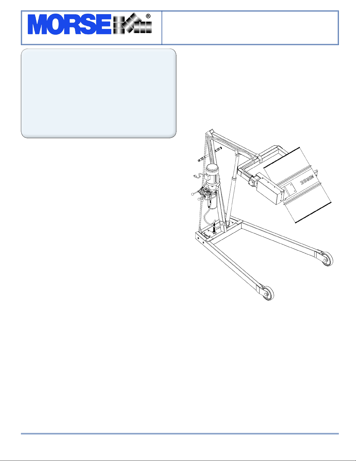
Model 400A-96-110
Hydra-Lift, 96”, AC Power Lift & Tilt
morsedrum.com
Copyright 2018 - Morse Mfg. Co., Inc. Form OM400A-96-110 (0409-1110) (Updated 14 Aug, 2018 3:30 PM) 1
CONTENTS
Page
Receiving Procedures. . . . . . . . . . . . . . . . . 1
Warranty. . . . . . . . . . . . . . . . . . . . . . . . . . . . . . . 1
Safety Information. . . . . . . . . . . . . . . . . . . . . 1 - 2
Machine Description. . . . . . . . . . . . . . . . . . . 3 - 4
Operating Instructions. . . . . . . . . . . . . . . . . . . 4 - 5
Maintenance. . . . . . . . . . . . . . . . . . . . . . . . . . 5
Safety Information
While Morse Manufacturing Co. drum handling equipment
is engineered for safety and efciency, a high degree of
responsibility must be placed upon the machine operator
to follow safe practices, based primarily on common sense,
upon which true safety depends.
Failure to follow the safety precautions in this manual can
result in personal injury or property damage. Observe
the same precautions as with similar machinery where
carelessness in operating or maintenance is hazardous to
personnel. Carefully read the safety precautions below and
throughout this manual.
Receiving Procedures
Every Morse drum handler is inspected prior to shipping.
However, damage may be incurred during transit.
• Check for visible damage. If you choose to accept
damaged freight, always sign noting the damage on the
BILL OF LADING.
• Document the damage and have the truck driver sign. We
recommend keeping a digital camera at your receiving
dock for this purpose.
• Open packages expeditiously to check the condition of the
goods. There is only a 24 hour window to notify the carrier
of any concealed damage.
• IMMEDIATELY REPORT ALL DAMAGE TO THE
SHIPPING COMPANY! Then you may contact Morse for
assistance with your freight claim.
• Morse Manufacturing will not be held responsible for any
damaged freight that is not signed for as damaged.
Delivery to non-business addresses without a loading dock
result in additional freight charges. Residential delivery
fees, inside delivery fees, re-delivery charges, and lift gate
services will be added by the truck line, and are non-
negotiable.
Limited 2 Year Warranty
Morse drum handling equipment is guaranteed against
defects in workmanship or materials for TWO YEARS when
used properly within its rated capacity. Warranty does not
cover wear from normal use or damage from accident
or abuse. Motors and other purchased parts carry the
warranties of their manufacturers.
For warranty claims, contact your Morse Dealer to obtain a
return authorization number, and for return freight advice.
Return freight must be prepaid.
In all instances, liability is limited to the purchase price paid
or to repairing or replacing the product. Customer assumes
liability for any modications, unauthorized repairs or parts
substitution.
Operator’s Manual
for Morse Hydra-Lift Drum Karrier
Model 400A-96-110
Serial Number 0409 to 1110 (MMYY)

The Specialist In Drum Handling Equipment
Model 400A-96-110
Hydra-Lift, 96”, AC Power Lift & Tilt
Operator’s Manual for Morse Hydra-Lift Karrier Model 400A-96-110
Serial Number 0409 to 1110 (MMYY)
morsedrum.com
Copyright 2018 - Morse Mfg. Co., Inc. Form OM400A-96-110 (0409-1110) (Updated 14 Aug, 2018 3:30 PM) 2
Safety Information (continued)
DANGER - Indicates a situation which, if not avoided, will result in
serious injury or death. This signal word is limited to the most extreme
situations.
WARNING - Indicates a situation which, if not avoided, could result in
serious injury or death.
CAUTION - Indicates a situation which, if not avoided, can result in
damage to the machine.
CAUTION – Do Not Transport with Drum Raised
ALWAYS LOWER THE DRUM HOLDER TO LOWEST POSITION BEFORE TRANSPORTING. The unit
can become unstable when transporting with a raised load.
DANGER - Stay Clear of Power Lines
KEEP WELL CLEAR OF POWER LINES. Never approach a power line. Current in a high voltage line
may arc some distance from the wire to the steel framed, grounded machine.
WARNING
The Hydra-Lift Karrier is designed to handle one drum of the types listed at the top of page 3, under 2.
Machine Description. DO NOT attempt to handle any other type of drum or object. DO NOT exceed
the weight capacity of 800 Lb.
WARNING - Level Floors Only
For operation only on clean, level oors of suitable bearing capacity. Do not use on sloped surfaces,
ramps, irregular or debris strewn oors.
WARNING - Do Not Modify the Unit
Under no circumstances should any modications be made to the Morse machinery without factory au-
thorization. Any modications may void the warranty. This machine was designed to perform a specic
job and alterations may result in injury to operator or machine.
WARNING - No Loose Fitting Clothing
Wear close-tting clothing and safety equipment appropriate to the job. Loose tting clothing may become
caught on the machinery and cause severe personal injury.
WARNING - Hydraulic Fluid Under Pressure Can Be Hazardous
Escaping hydraulic uid under pressure can penetrate the skin, causing serious injury. Avoid the hazard
by relieving pressure before disconnecting hydraulic lines. Keep hands and body away from pinholes
and nozzles, which eject uid under high pressure. Use a piece of cardboard to search for leaks. If an
accident occurs, see a doctor immediately and inform them of the nature of the accident.
CAUTION - Wear Safety Shoes - Wear safety shoes with non-slip soles and hard toe protection.
WARNING: This product can expose you to chemicals including cobalt, titanium dioxide, and
2-methylimidazole, which are known to the State of California to cause cancer, and bisphenol-A,
which is known to the State of California to cause birth defects or other reproductive harm. For more
information go to www.P65Warnings.ca.gov

The Specialist In Drum Handling Equipment
Model 400A-96-110
Hydra-Lift, 96”, AC Power Lift & Tilt
Operator’s Manual for Morse Hydra-Lift Karrier Model 400A-96-110
Serial Number 0409 to 1110 (MMYY)
morsedrum.com
Copyright 2018 - Morse Mfg. Co., Inc. Form OM400A-96-110 (0409-1110) (Updated 14 Aug, 2018 3:30 PM) 3
Machine Description
The Model 400A-96-110 Hydra-Lift Karrier will pour a drum up to
96” high, measured from the oor to the lowest point of a horizontal
drum. It is designed to lift, transport, and dispense a 55-gallon steel
or ber drum 22” to 23.5” in diameter.
The maximum full-drum capacity is 800 Lb. The capacity is derated
to 500 Lb. for a half-full drum. The half-full rating is based on the
tilt mechanism’s capacity for handling an unbalanced bottom-heavy
drum.
Options
A smaller diameter drum can be handled with the correct size•
55/30 Series Diameter Adaptor installed (see Diameter Adaptor
literature).
The adjustable Bracket Assembly (Part # 4556-P) is • required
to handle a plastic drum without a top rim (see gure 2.1). The
Bracket Assembly is also recommended when handling a ber
drum. You can also use the Bracket Assembly when handling
a rimmed drum.
To handle a 55-gallon plastic drum with suitable top rim, you •
must install either the Bracket Assembly or the Top Rim Clamp
(Part # 4596-P) (see gure 2.2). You can use the Top Rim
Clamp to handle a 55-gallon plastic, steel or ber drum with
suitable top rim.
Controls
The Morse Hydra-Lift Karrier is manually propelled and steered. The drum
lift and tilt controls are powered by a single phase 115V AC motor with a
momentary switch, cord and plug.
There are two functions for the operator to control (Figure 2.3):
1. “LIFT” and lower function for vertical positioning of the drum
2. “TILT” function to control the degree of rotation of the drum
1. LIFT and Lower Function
To raise the drum
a. Plug the motor into a standard 115V power supply.
b. Turn the motor on by holding the momentary switch in the on position.
c. With the motor on, raise the LIFT handle.
To lower the drum
a. With the motor off, push in the LOWER handle.
2. TILT Function
To tilt the drum forward for pouring
a. Turn on the motor by holding momentary switch in the on position.
b. With the motor on, raise the tilt handle.
To return the drum to vertical position
a. Turn on the motor by holding momentary switch in the on position.
b. Push the tilt handle down.
Figure 2.3
Figure 2.2
Plastic drum being lifted
with part number 4596-P
Top Rim Clamp Assembly
installed.
Figure 2.1
Plastic drum being lifted with
part number 4556-P Bracket
Assembly installed.

The Specialist In Drum Handling Equipment
Model 400A-96-110
Hydra-Lift, 96”, AC Power Lift & Tilt
Operator’s Manual for Morse Hydra-Lift Karrier Model 400A-96-110
Serial Number 0409 to 1110 (MMYY)
morsedrum.com
Copyright 2018 - Morse Mfg. Co., Inc. Form OM400A-96-110 (0409-1110) (Updated 14 Aug, 2018 3:30 PM) 4
WARNING - Watch Out for Pinch Points
Stay clear of moving parts. Operator should remain behind the push handle during the lift operation.
Figure 3.2
Floor Lock
The screw-down oor lock is located on the base of the tower
(gure 3.1). Turning the oor lock clockwise until it locks in the
down position activates the oor lock. When the oor lock is
activated it prevents unwanted free wheeling of the unit. Floor
conditions determine the effectiveness of the oor lock. The
operator should verify its holding action before depending on
it to hold.
MORcinch Drum Holder Assembly
The drum holder assembly (or “saddle assembly”) is the
component on the Hydra-Lift Karrier that is intended to hold
the drum. The MORcinch drum holder assembly is designed
to secure a standard ribbed 55-gallon steel drum around it’s
middle using a cinch chain and ratchet tightening system. The
MORcinch drum holder accepts accessories for handling a
plastic drum, a ber drum, or smaller diameter drums (see
Options on pg. 3).
Operating Instructions
1.) Push the Hydra-Lift Karrier to the drum.
2.) Using the “LIFT” control as described in “Machine De-
scription - Controls” (page 3) , position the drum holder
assembly with the back band at the middle of the drum.
(Figure 3.1). With the ratchet plate swung open and the
cinch chain hanging from the chain hook, push the unit
until the back band rests rmly against the drum. Some
adjustment to the tilt angle of the saddle may be necessary
to ensure band ts ush on the drum.
3.) Attaching the drum:
Drape the chain across the front of the drum and engage a
link into the slot in the ratchet (Figure 3.2). Turn the ratchet
clockwise to tighten chain. If ratchet turns until the pawl is
beyond the last ratchet tooth, turn the ratchet back and slide
the next link into the ratchet slot and try tightening again.
The chain must be held tightly against the drum with the
pawl engaged securely in the ratchet teeth.
4.) Operate the lift function to lift drum clear of oor. Roll to
dispensing location. NOTE: Do not allow the drum to
impact on oor, pouring station, etc. or a spill or damage
could occur.
Figure 3.1

The Specialist In Drum Handling Equipment
Model 400A-96-110
Hydra-Lift, 96”, AC Power Lift & Tilt
Operator’s Manual for Morse Hydra-Lift Karrier Model 400A-96-110
Serial Number 0409 to 1110 (MMYY)
morsedrum.com
Copyright 2018 - Morse Mfg. Co., Inc. Form OM400A-96-110 (0409-1110) (Updated 14 Aug, 2018 3:30 PM) 5
CAUTION – Do Not Transport with Drum Raised
ALWAYS LOWER THE DRUM HOLDER TO LOWEST POSITION BEFORE TRANSPORTING. The
unit can become unstable when transporting with a raised load.
5.) Lift drum to desired pouring height. Operate the tilt control as described in “Machine Description - Controls” (page 3)
to adjust the drum attitude. This is especially important when lifting an open drum. The oor lock should be engaged while
dispensing / draining.
6.) When dispensing is complete, tilt drum back to upright position. Disengage the oor lock and lower the drum to transport-
ing height; about 6” off the oor.
WARNING - Stay Clear of Raised Drum
NEVER allow anyone to be below any part of a raised drum handler or drum. Remain behind the
push handle while handling a drum.
WARNING – Do NOT Disengage the Cinch Chain When Drum is off the Ground
When the drum is in the upright position, lower the drum to the oor before releasing the cinch
chain.
7.) Push the unit to the drum storage area and lower to the oor in an upright position. Release the cinch chain from the
ratchet by applying pressure to the ratchet handle in a clockwise direction with one hand and opening the pawl to free
the ratchet with the other hand. Remove the cinch chain link from the ratchet.
Maintenance
Periodic inspection for the general condition of structural and mechanical components is imperative for safe and efcient
operation.
Periodically inspect all moving parts, framework, and contact areas for signs of wear, fatigue, or loosening. Tighten, adjust,
or replace parts as necessary to prevent failure and maintain proper function.
Inspect the hydraulic system for oil drips, hose damage, or other signs of wear. Inspect the level and condition of the hydraulic
uid. Replace any parts that show signs of wear.
Grease wheel bearings periodically. Oil or grease all moving parts including: the three clevis pins and the surfaces of the boom
which contact the inside of the mast cap, the hinge pin, the gears and sprockets in the tilt drive, and the ratchet and pawl.
Worn or damaged parts must be properly replaced with the correct, genuine Morse parts.
Hydraulic pump is shipped lled with Noco Premium plus automatic transmission uid d/m. Material safety data sheet
(msds) is available online. Change oil yearly, sooner depending on dirty conditions or outdoor use. Replace oil with Mobil
dte 24 or equivalent for indoor use (Mobil dte 13 for outdoor use).
Other manuals for 400A-96-110
2
This manual suits for next models
2
Other morse Storage manuals

morse
morse 400AM-72 User manual

morse
morse 185G User manual

morse
morse 400A-72-124 User manual

morse
morse 515-N-124 User manual

morse
morse 80APS User manual

morse
morse 400A-60-115 User manual

morse
morse MORCINCH 4556M-P User manual

morse
morse 82A-125 User manual

morse
morse 400A-72 User manual

morse
morse 0804 User manual

morse
morse 400A-96-114 User manual

morse
morse 400AM-60-124 User manual

morse
morse 400A-96-124 User manual

morse
morse Hydra-Lift 400A-60 User manual

morse
morse 4560M-P User manual

morse
morse 185HD SERIES User manual

morse
morse 310 Series User manual

morse
morse 400AM-96-124 User manual

morse
morse 400A-72 User manual

morse
morse 287-2H User manual


