MORSE Mfg. Co., Inc. •727 West Manlius Street •P.O. Box 518 •East Syracuse, NY 13057-0518
Phone:
(315)
437-8475
•Fax: (315) 437-1029 •Email: [email protected] •Website: www.morsedrum.comCopyright 2009 - Morse Mfg. Co., Inc. Form PL400-60-115 (0103-0309) (Updated 01/2009) Page 1
The Specialist In Drum Handling Equipment
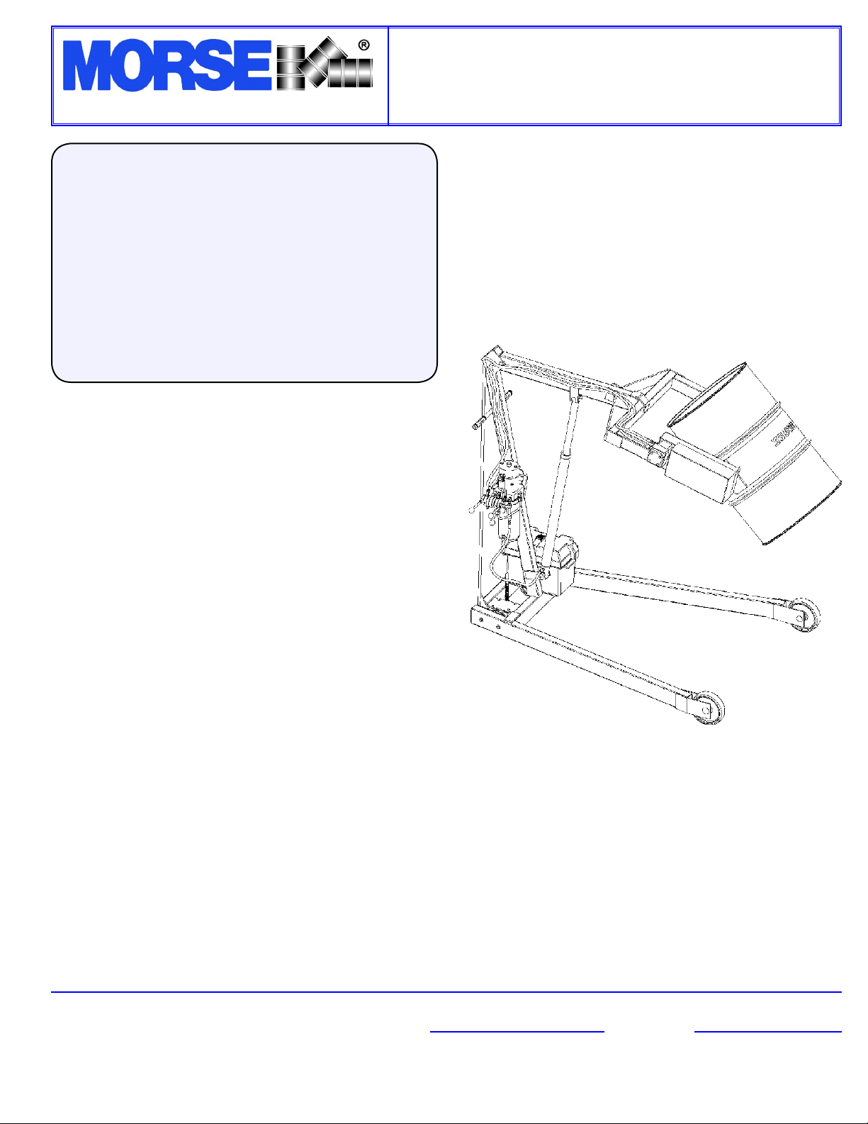
Model 400A-60-115
Hydra-Lift, 60”, DC Power Lift & Tilt
Contents
Page
Receiving Procedures. . . . . . . . . . . . . . . . . 1
Warranty. . . . . . . . . . . . . . . . . . . . . . . . . . . . . . . 1
Safety Information. . . . . . . . . . . . . . . . . . . . . 1 - 2
Machine Description. . . . . . . . . . . . . . . . . . . 3 - 4
Operating Instructions. . . . . . . . . . . . . . . . . . . 4 - 5
Maintenance. . . . . . . . . . . . . . . . . . . . . . . . . . 5
Parts Lists and Diagrams. . . . . . . . . . ......6-9
Safety Information
While Morse Manufacturing Co. drum handling equipment is engi-
neered for safety and efciency, a high degree of responsibility must
be placed upon the machine operator to follow safe practices, based
primarily on common sense, upon which true safety depends.
Failure to follow the safety precautions in this manual can result in
personal injury or property damage. Observe the same precautions as
with similar machinery where carelessness in operating or maintenance
is hazardous to personnel. Carefully read the safety precautions below
and throughout this manual.
Receiving Procedures
Every Morse drum handler is inspected prior to shipping. However,
damage may be incurred during transit.
• Check for visible damage. If you choose to accept damaged
freight, always sign noting the damage on the BILL OF LADING.
• Document the damage and have the truck driver sign. We rec-
ommend keeping a digital camera at your receiving dock for this
purpose.
• Open packages expeditiously to check the condition of the goods.
There is only a 24 hour window to notify the carrier of any con-
cealed damage.
• IMMEDIATELY REPORT ALL DAMAGE TO THE SHIPPING
COMPANY! Then you may contact Morse for assistance with your
freight claim.
• Morse Manufacturing will not be held responsible for any damaged
freight that is not signed for as damaged.
Delivery to non-business addresses without a loading dock result in
additional freight charges. Residential delivery fees, inside delivery
fees, re-delivery charges, and lift gate services will be added by the
truck line, and are non-negotiable.
Limited 2 Year Warranty
Morse drum handling equipment is guaranteed against defects in
workmanship or materials for TWO YEARS when used properly
within its rated capacity. Warranty does not cover wear from normal
use or damage from accident or abuse. Motors and other purchased
parts carry the warranties of their manufacturers.
For warranty claims, contact your Morse Dealer to obtain a re-
turn authorization number, and for return freight advice. Return
freight must be prepaid.
In all instances, liability is limited to the purchase price paid or to re-
pairing or replacing the product. Customer assumes liability for any
modications, unauthorized repairs or parts substitution.
Operator’s Manual
for Morse Hydra-Lift Drum Karrier
Model 400A-60-115
Serial Number 0103 to 0309 (MMYY)


