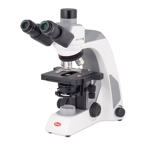
Motic B1 Series User manual

WWW.MOTIC.COM
MOTIC INCORPORATION LTD.
B1 SERIES
Biological Microscope
Instruction Manual
If the equipment is used in a manner
not specified by the manufacturer,
the protection provided by the
equipment may be impaired.
Note
E250223

We are constantly endeavouring to improve our instruments and to adapt them to the requirements of
modern research techniques and testing methods. This involves modification to the mechanical
structure and optical design of our instruments.
Therefore, all descriptions and illustrations in this instruction manual, including all specifications are
subject to change without notice.

2
TABLE OF CONTENTS
MICROSCOPE TERMINOLOGY 4
1. Safety Instructions 6
1.1 General safety instructions 6
1.2 Instrument safety 6
1.3 Unpacking, transportation & storage 6
1.4 Waste disposal 6
1.5 Operation 7
1.6 Quality Warranty 8
2. Nomenclature 9
3. SETTING UP THE INSTRUMENT 10
3.1 Operating environment 10
3.2 Verifying input voltage 10
4. Assembling The Microscope 11
4.1 Illumination 11
4.2 Specimen holder 13
4.3 Objectives 13
4.4 Condenser 13
4.5 Eyepiece tube 13
4.6 Eyepieces 13
4.7 Filters 13
4.8 Power cord 13

3
5. Microscope Handling 14
5.1 Illumination brightness adjustment 14
5.2 Interpupillary distance adjustment 14
5.3 Diopter adjustment 14
5.4 Beam splitter lever (trinocular version) 15
5.5 Coarse and fine focusing 15
5.6 Coarse focus torque adjustment 16
5.7 Stage Upper Limit Stop adjustment: 16
5.8 Use of aperture diaphragm 17
6. Photomicrographic Procedure 18
7. Using Oil Immersion Objective 19
8. Troubleshooting Table 20
8.1 Optical 20
8.2 Electrical 21
9. Care And Maintenance 22
9.1 Cleaning the Microscope 22
9.1.1 Lenses and filters 22
9.1.2 Cleaning of painted or plastic components 22
9.2 Disinfecting the Microscope 22
9.3 When not in use 22
10. Warning Labels 23

4
MICROSCOPE TERMINOLOGY
Abbe Condenser
A two-lens sub-stage condenser located below
the stage of a microscope and functions to collect
light and direct it onto the object being examined.
Its high numerical aperture makes it particularly
suited for use with most medium- and high-
magnification objectives.
Aperture, Numerical (N.A.)
The numerical aperture is an important factor
determining the efficiency of the condenser and
objective. It is represented by the formula: (N.A.
= ηsinα), where ηis the refractive index of a
medium (air, water, immersion oil etc.) between
the objective and the specimen or condenser,
and αis half of the maximum angle at which light
enters or leaves the lens from or to a focused
object point on the optical axis.
Cover Glass Thickness
Transmitted light objectives are designed to
image specimens that are covered by a thin
cover glass (cover slip). The thickness of this
small glass piece is now standardized at 0.17
mm for most applications.
Diaphragm, Condenser
A diaphragm, which controls the effective size of
the condenser aperture. A synonym for the
condenser illuminating aperture diaphragm.
Depth of Focus
The axial depth of the space on both sides of the
image plane within which the image is sharp. The
larger the N.A. of objective, the shallower the depth
of focus.
Field of View (F.O.V.)
That part of the image field, which is imaged on the
observer’s retina, and hence can be viewed at any
one time. The field of view number is now one of
the standard markings of the eyepiece.
Filter
Filters are optical elements that selectively transmit
light. It may absorb part of the spectrum, or reduce
overhaul intensity or transmit only specific
wavelengths.
Immersion Oil
Any liquid occupying the space between the object
and microscope objective. Such a liquid is usually
required by objectives of 3-mm focal length or less.
Magnification
The number of times by which the size of the
image exceeds the original object. Lateral
magnification is usually meant. It is the ratio of the
distance between two points in the image to the
distance between the two corresponding points in
the object.
Micrometer: um
A metric unit of length measurement
= 1x10⁻⁶ meters or 0.000001 meters
5
Diopter adjustment
The adjustment of the eyepiece of an instrument
to provide accommodation for the eyesight
differences of individual observers.
Real field of view
The diameter in millimetres of the object field.
Eyepiece Field of View
Real field of View =
Objective Magnification
Resolving Power
A measure of an optical system's ability to
produce an image which separates two points or
parallel lines on the object.
Resolution
The result of displaying fine details in an image
Total Magnification
The total magnification of a microscope is the
individual magnifying power of the objective
multiplied by that of the eyepiece.
Nanometer (nm)
A unit of length in the metric system equal to 10-9
meters.
Working Distance
This is the distance between the objective front
lens and the top of the cover glass when the
specimen is in focus. In most instances, the
working distance of an objective decreases as
magnification increases.
X–axis
The axis that is usually horizontal in a two-
dimensional coordinate system. In microscopy X-
axis of the specimen stages is considered that
which runs left to right.
Y–axis
The axis that is usually vertical in a two-
dimensional coordinate system. In microscopy Y-
axis of the specimen stages is considered that
which runs front to back.

6
1.SAFETY INSTRUCTIONS
1.1 General safety instructions
Please be sure to read these instructions before using microscope. Additional information is available
upon request from our maintenance department or authorized agency. To ensure safe operation and
guarantee good performance of the microscope please pay attention to the precautions and warnings
specified in the Operation Instructions. In this Operation Instructions manual, the following symbols
indicate:
Caution! Electric shock hazard!
Caution! Danger!
1.2 Instrument safety
The microscope has been designed, manufactured and inspected according to the IEC 61010-1:2001
Safety Requirements for Electrical Equipment for Measurement, Control and Laboratory Use.
1.3 Unpacking, transportation & storage
The original shipping container should be kept for use in long term storage or return shipment.
Please comply with the temperature requirements for transport and storage.
●Transport (within package)
Permissible environment temperature: -40 ~ +70°C
●Storage
Permissible environment temperature: +10 ~ +40°C
Permissible relative humidity: Below 31°C, max. humidity is 80%; at 40°C, linearly
decreases to 50%
1.4 Waste disposal
Important: Any damaged microscope must not be treated as general waste; it should be disposed of
according to relevant regulations.

7
1.5 Operation
When using the microscope, please pay attention to the following safety instructions:
●If it is used for any purpose other than the specified ones, including any individual component or
part, the manufacturer will not take any responsibility.
●After-sales service or repair done by unauthorized personnel will void the warranty.
●Anyone who uses the instrument should receive instruction on the proper handling of the
instrument and safety practices for microscopy. The microscope shall be placed only on a firm, flat
workbench for operation.
●Since the microscope is a precision instrument, improper operation will impair or spoil its
performance.
●The power unit is integrated in the main unit of the microscope: the grid supply voltage is within
100-240V~ 50Hz-60Hz.
The microscope must be connected only to the normal power socket with a grounding
terminal. Any extension cord without ground protection is not allowed to avoid failure of the
protection function.
If there is any electrical failure (of the fuse system, ground protection or transformer), turn off
and unplug the unit immediately. Make sure the microscope is set aside so it will not be used
again and contact the Motic service department or a Motic microscope repair agency to have
it repaired.
Please be sure to turn off the power before opening the instrument to replace the lamp or
replace the fuse! Only use a fuse for the rated current.
Safety instructions for the use of immersion oil.
Immersion oil is irritating to skin; avoid contact with skin, eyes and clothing.
Skin contact: wash with soap and plenty of water until the immersion oil is completely
removed.
Eye contact: flush immediately with plenty of water for at least 5 minutes. If irritation persists,
seek medical advice.
Dispose of immersion oil properly. Do not discharge into surface water or sewage.
The microscope is not equipped with any special device to protect against corrosive, latent infective,
toxic, radioactive or other hazardous samples. Therefore, when examining any such sample you must
comply with the relevant laws and regulations, in particular the provisions related to accident prevention.

8
1.6 Quality Warranty
The microscope and the attached accessories are only allowed to be used for microscope examination
as described in this manual. The manufacturer takes no responsibility for any other use.
●The manufacturer guarantees that the product is free from any defect in material or workmanship
on the date of delivery.
●If any defect is found, notify the manufacturer immediately.
●Upon receipt of the Notification of Defect as described above, the manufacture is responsible to
solve the problem either by repairing the defective instrument or replacing it with a new instrument
of the same model.
●The manufacturer provides no warranty for any failure or defect due to normal wear and tear or
improper use of the product.
●The manufacturer takes no responsibility for any damage caused by operation error, negligence or
unauthorized dismantling of the instrument, or the use of spare parts from other manufacturers.

9
2.NOMENCLATURE
MOTIC B1 (Binocular)

10
3.SETTING UP THE INSTRUMENT
The microscope shall be placed only on a firm, flat workbench for operation.
Avoid placing the instrument in locations exposed to direct sunlight, dust, vibration, high temperature,
high humidity and where it is difficult to unplug the power supply cord.
Please do not touch the optical lens surfaces.
3.1 Operating environment
●Indoor use
●Altitude: Max 2000 meters
●Ambient temperature: 5°C to 40°C
●Maximum relative humidity: 75% for temperature up to 31°C decreasing linearly to 50% relative
humidity at 40°C
●Supply voltage fluctuations: Not to exceed ±10% of the normal voltage
●Pollution degree: 2 (in according with IEC60664)
●Installation/Overvoltage category: 2 (in according with IEC60664)
●Air Pressure of 75kPa to 106kPa
●Avoid frost, dew, percolating water, and rain
3.2 Verifying input voltage
The automatic voltage selection works with a broad range of settings. However, always use a power
cord that is rated for the voltage used in your area and that has been approved to meet local safety
standards.
Using the wrong power cord could cause fire or equipment damage.
In case of using an extension cord, use only a power supply cord with a protective earth (PE) wire.
In order to prevent electric shock, always turn the power switch on the power supply off before
connecting the power cord.
Transmitted illumination electrical specifications:
●LED
Input: 100-240V~, 50-60Hz
Output: 12V 2A or 12V 0.5A
LED: 3.4V / 3W

11
4.ASSEMBLING THE MICROSCOPE
The components for microscopes are shipped detached for protection. Open the Styrofoam packing
with care and do not leave any components attached to the packing being removed.
Do not discard any of the packing materials until all of the components have been identified. If any
damage occurs during transit, contact both the carrier and your supplier immediately.
When handling the components, especially the optical parts, avoid touching any lens surfaces with bare
hands or fingers as fingerprints and grease stains affect image quality.
All the steps described for the assembly of the microscope must be undertaken with extreme care and
without forcing the placement of the distinct parts and elements of the microscope.
4.1 Illumination
The following points describe how to replace the bulbs.
Make sure that the brightness control is in the minimum position before turning on or off the power
switch.
●Unscrew five hexagonal screws retaining the base plate.

12
●Disconnect the LED connection cables from the power supply printed circuit board.
●Loosen LED board locating ring, take away LED board locating ring.
Install the new LED
●Take out a qualified LED groups with power and PIN, nest the pressure ring and reverse action
steps as above.
●At the time of installation, the LED group centre should be adjusted to the center of collector as
possible, which is called the axis centre.
●When installing the bulb, do not touch the glass surface of the bulb with bare fingers.
●Doing so will cause fingerprints, grease, etc., to burn onto the bulb surface, reducing the
Illumination provided by the bulb. If the surface is contaminated, wipe it clean using lens tissue.

13
4.2 Specimen holder
Attach the specimen holder, using the two mounting holes.
4.3 Objectives
Lower the stage completely by turning the coarse focus knob. Screw the objectives into the revolving
nosepiece so that clockwise rotation of the nosepiece brings the next higher magnification objective into
position.
4.4 Condenser
●Raise the stage by turning the coarse focus knob.
●Completely lower the condenser carrier by turning the condenser focus knob.
●Insert the condenser into the mount with aperture scale facing forward towards the user.
●Secure it with the condenser clamp screw.
●Turn the condenser focus knob to raise the condenser as far as it will go.
4.5 Eyepiece tube
Loosen the eyepiece tube clamp screw. Insert the round dovetail mount on the eyepiece tube into the
round dovetail mount on the microscope arm. Tighten the eyepiece tube clamp screw to secure the
eyepiece tube in place.
4.6 Eyepieces
Use the same magnification eyepieces for both eyes.
Inserting or removing the eyepieces is facilitated by twisting the eyepieces when pushing in or pulling
out.
Monocular version: Before inserting or removing the eyepiece loose the clamp screw.
4.7 Filters
A special diffuser system is build into the illumination beam path and guaranties a homogeneous light
distribution.
4.8 Power cord
Connect the socket of the of the power cord to the AC inlet on the rear of the base of the microscope.
Plug in the other end of the cord to an AC outlet with ground conductor.

14
5.MICROSCOPE HANDLING
5.1 Illumination brightness adjustment
Turn the brightness adjustment knob fully clockwise to the low brightness position.
Set the power switch to “I” (ON).
The green line control lamp in the switch must light up.
When the Brightness adjustment knob is turned counterclockwise to the high brightness position, the
light intensity increases.
5.2 Interpupillary distance adjustment
Before adjusting the interpupillary distance, bring a specimen into focus using the 10x objective.
●Adjust the interpupillary distance so that both the right and left field of view become one.
●This adjustment will enable the user to observe the specimen with both eyes
5.3 Diopter adjustment
Diopter adjustment compensates for the differences in vision between the left and right eyes. In
addition to making observation through both eyes easier, this adjustment also reduces the extent to
which focusing is lost when the objective magnification is changed. In particular, this occurs when a
low magnification objective is used.
●Set the diopter on both eyepieces to the “0” position.
●Change to 10x Magnification and focus the image of the specimen with one eye only.
●Use the Eye which is most convenient for first focussing.
●When the best focus position is reached, close this eye and use the other eye for the following
steps.

15
●Correct the focus for the second eye by using only the diopter ring, do not use the coarse/fine
focusing knob!
●Change to a higher magnification to verify the result and if necessary repeat the procedure to
match the sharpness for higher magnification.
●Keep this final diopter position for all magnification/lenses. The diopter position for each user can
be recorded from the scale, so it can easily be reset.
5.4 Beam splitter lever (trinocular version)
The beam splitter lever of the trinocular eyepiece tube can be used to select the amount of light
distributed between the trinocular eyepiece tube and the vertical phototube.
●When the beam splitter lever is pushed in, 100% of the light will enter the eyepieces.
●When it is in the mid-position, adjusted until a click is heard, 100% of the image is directed to the
trinocular port for photographs or video images.
●When pulled out, the light beam will be divided as follows:
30% of the image is directed to the binocular eyepieces, and 70% to the trinocular port.
5.5 Coarse and fine focusing
●Focusing is carried out with the coarse and fine focus knobs at the left and right of the microscope
stand.
●The direction of vertical movement of the stage corresponds to the turning direction of the focus
knobs.
●One rotation of the fine focus knob moves the stage 0.2mm. The graduation on the fine focus knob
is 1 micron.

16
5.6 Coarse focus torque adjustment
To increase the torque, turn the torque adjustment ring located behind the left-hand coarse focus knob
in the direction indicated by the arrow. To reduce the torque, turn the ring in the direction opposite to
that indicated by the arrow.
5.7 Stage Upper Limit Stop adjustment:
(Upper Stage Limit is preset at the factory; please only adjust if necessary)
●The Stage Upper Limit Stop marks the stage position by restricting the movement of the coarse
focus knob.
●With the specimen in focus, turn the stage upper limit stop screw clockwise until it reaches the
stop.
●When the stage upper limit stop is in position, the stage cannot be raised from that position.
However, the fine focus knob can move the stage regardless of the limit but will only lower the
stage.
●Lower the stage by using the coarse focus knob anticlockwise.
Never attempt either of the following actions, since doing so will damage the focusing
mechanism:
●Rotate the left and right knob while holding the other.
●Turning the coarse and fine focus knobs further than their limit.

17
5.8 Use of aperture diaphragm
●The condenser aperture diaphragm is provided for adjusting the numerical aperture (N.A.) of the
illuminating system of the microscope, it decides the resolution of the image, contrast, depth of
focus and brightness.
●Stopping down will lower the resolution and brightness but increase the contrast and depth of
focus.
●An image with appropriate contrast in most cases can be obtained with an aperture diaphragm
closed down to 2/3 of the maximum value.
Suggested apertures for each objective are as follows:
OBJECTIVE APERTURE OF IRIS
4X From fully closed to 1/8 open.
10X From 1/8 to 1/4
40X From 1/4 to 1/2
100X From 1/2 to 3/4

18
6.PHOTOMICROGRAPHIC PROCEDURE
To ensure vibration free operation, set the microscope on a sturdy vibration free table or a bench with a
vibration proof device.
●Pull the bean splitter lever of the trinocular eyepiece tube all of the way out to the limit.
○When the beam splitter lever is pushed in, 100% of the light will enter the eyepieces.
○The triple position tube is the most flexible tube by giving 2 photo positions:
30:70 (visual: photo; for simultaneous observation by eyepiece and camera)
0:100 (visual: photo; for low light situations)
●To ensure optimal illumination, check the position of the condenser.
●An additional colour-compensating filter can also be used depending on the colour rendition.
●A change in depth of focus, contrast and resolution of the image is attainable with an aperture
setting of 2/3 of the maximum diaphragm diameter. Fine setting of the condenser aperture varies
with the individual sample.
●For specific photomicrographic procedures, refer to the manual of the specific camera being used.

19
7.USING OIL IMMERSION OBJECTIVE
Oil immersion objectives are labelled with the additional engraving “Oil” and are to be immersed in oil
between the specimen and the front of the objective.
The immersion oil supplied by Motic is synthetic, non-fluorescing and non-resining oil, with a refractive
index of 1.515
Normally, cover glass must be used with oil immersion objectives with a few exceptions. Deviations
from thickness are not important as a layer of immersion oil acts as compensation above the cover
glass.
The small bottle of oil supplied with every immersion objective facilitates application of the oil to the
cover slip.
●Remove any air bubbles in the nozzle of the oil container before use.
●Immersion oil must be used sparingly. After the examination, the oil should be wiped off the
objective with a lens cleaning tissue and the residual film removed with soft cloth moistened with
petroleum benzene or absolute alcohol.
●Locate the field of interest with a lower magnification objective. Swing the objective out of the light
path, and add one drop of immersion oil over the site of the specimen. Swing in the oil immersion
objective. There should be a small column of oil from the cover slip to the objective lens. Use the
fine focus to make the image sharp.
●Freedom from air bubbles must be ensured. To check for air bubbles, remove an eyepiece, fully
open the field and aperture diaphragms, and look at the exit pupil of the objective within the
eyepiece tube. Air bubbles are recognized by a surrounding black ring. Bubbles may often be
dislodged by moving the slide to and fro or by slightly rocking the revolving nosepiece back and
forth. If not successful in clearing the bubbles then the oil must be wiped off and replaced with a
fresh drop.
Other manuals for B1 Series
1
Table of contents
Other Motic Microscope manuals

Motic
Motic ECO Series User manual

Motic
Motic K Series User manual

Motic
Motic SFC-100 Series User manual

Motic
Motic Moticam User manual

Motic
Motic PM-1805 User manual

Motic
Motic MOTICAM T2 User manual

Motic
Motic M3600 Series User manual

Motic
Motic BA410 Series User manual

Motic
Motic BA210 series User manual

Motic
Motic BA310 Pol User manual

Motic
Motic BA310 Pol User manual

Motic
Motic SMZ-161B User manual

Motic
Motic SMZ-140 User manual

Motic
Motic AE2000MET User manual

Motic
Motic SILVER250 Series User manual

Motic
Motic RED 200 Series User manual

Motic
Motic BA310 Pol User manual

Motic
Motic 1100401200572 User manual

Motic
Motic SILVER3H Series User manual

Motic
Motic BA80 Series User manual