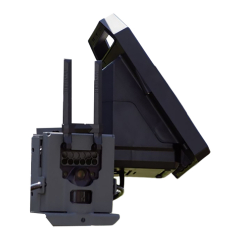
Motorola solutions L6Q User manual

L6Q Installation Guide
*MN008660A01*
MN008660A01-AC
DECEMBER 2022
© 2022 Motorola Solutions, Inc. All rights reserved

Legal and Support
Intellectual Property and Regulatory Notices
Copyrights
The Motorola Solutions products described in this document may include copyrighted Motorola
Solutions computer programs. Laws in the United States and other countries preserve for Motorola
Solutions certain exclusive rights for copyrighted computer programs. Accordingly, any copyrighted
Motorola Solutions computer programs contained in the Motorola Solutions products described in this
document may not be copied or reproduced in any manner without the express written permission of
Motorola Solutions.
No part of this document may be reproduced, transmitted, stored in a retrieval system, or translated
into any language or computer language, in any form or by any means, without the prior written
permission of Motorola Solutions, Inc.
Trademarks
MOTOROLA, MOTO, MOTOROLA SOLUTIONS, and the Stylized M Logo are trademarks or
registered trademarks of Motorola Trademark Holdings, LLC and are used under license. All other
trademarks are the property of their respective owners.
License Rights
The purchase of Motorola Solutions products shall not be deemed to grant either directly or by
implication, estoppel or otherwise, any license under the copyrights, patents or patent applications
of Motorola Solutions, except for the normal non-exclusive, royalty-free license to use that arises by
operation of law in the sale of a product.
Open Source Content
This product may contain Open Source software used under license. Refer to the product installation
media for full Open Source Legal Notices and Attribution content.
European Union (EU) and United Kingdom (UK) Waste of Electrical and
Electronic Equipment (WEEE) Directive
The European Union's WEEE directive and the UK's WEEE regulation require that products sold
into EU countries and the UK must have the crossed-out wheelie bin label on the product (or the
package in some cases). As defined by the WEEE directive, this crossed-out wheelie bin label means
that customers and end-users in EU and UK countries should not dispose of electronic and electrical
equipment or accessories in household waste.
Customers or end-users in EU and UK countries should contact their local equipment supplier
representative or service centre for information about the waste collection system in their country.
Disclaimer
Please note that certain features, facilities, and capabilities described in this document may not be
applicable to or licensed for use on a specific system, or may be dependent upon the characteristics of
a specific mobile subscriber unit or configuration of certain parameters. Please refer to your Motorola
Solutions contact for further information.
© 2022 Motorola Solutions, Inc. All Rights Reserved
MN008660A01-AC
Legal and Support
2

Legal and Compliance Statements
Supplier's Declaration of Conformity
Per FCC CFR 47 Part 2 Section 2.1077(a)
Responsible Party
Name: Motorola Solutions, Inc.
Address: 2000 Progress Pkwy, Schaumburg, IL. 60196
Phone Number: 1-800-927-2744
Hereby declares that the product:
Model Name: L6Q
conforms to the following regulations:
FCC Part 15, subpart B, section 15.107(a), 15.107(d), and section 15.109(a)
Class B Digital Device
As a personal computer peripheral, this device complies with Part 15 of the FCC Rules. Operation
is subject to the following two conditions:
1This device may not cause harmful interference, and
2This device must accept any interference received, including interference that may cause unde-
sired operation.
NOTE:
This equipment has been tested and found to comply with the limits for a Class B
digital device, pursuant to part 15 of the FCC Rules. These limits are designed to pro-
vide reasonable protection against harmful interference in a residential installation. This
equipment generates, uses and can radiate radio frequency energy and, if not installed
and used in accordance with the instructions, may cause harmful interference to radio
communications. However, there is no guarantee that interference will not occur in a
particular installation.
If this equipment does cause harmful interference to radio or television reception, which
can be determined by turning the equipment off and on, the user is encouraged to try to
correct the interference by one or more of the following measures:
• Reorient or relocate the receiving antenna.
• Increase the separation between the equipment and receiver.
• Connect the equipment into an outlet on a circuit different from that to which the
receiver is connected.
• Consult the dealer or an experienced radio or TV technician for help.
MN008660A01-AC
Legal and Support
3

For country code selection usage (WLAN devices)
NOTE: The country code selection is for non-US model only and is not available to all US
models. Per FCC regulation, all Wi-Fi products marketed in the US must be fixed to US
operation channels only.
Notice to Users (FCC)
This device complies with Part 15 of the FCC rules per the following conditions:
• This device may not cause harmful interference.
• This device must accept any interference received, including interference undesired operation.
• Changes or modifications made to this expressly approved by Motorola Solutions, could authority of
the user to operate this equipment.
Important Safety Information
ATTENTION!
This device is designed to meet General Population usage. Before using the device, read the
RF Energy Exposure and Product Safety Guide for the devices which contains important operating
instructions for safe usage and RF energy awareness and control for Compliance with applicable
standards and Regulations.
Any modification to this device, not expressly authorized by Motorola Solutions, may void the user's
authority to operate this device.
Contact Us
For inquiries, see https://www.motorolasolutions.com/en_us/support.html > License Plate
Recognition (Vigilant) or contact our 24 hours support staff at:
• Tel: 925-398-2079
• Fax: 925-398-2113
• Email: [email protected]
MN008660A01-AC
Legal and Support
4

Read Me First
Notations Used in This Manual
Throughout the text in this publication, you notice the use of Warning, Caution, and Notice. These
notations are used to emphasize that safety hazards exist, and the care that must be taken or
observed.
WARNING: An operational procedure, practice, or condition, and so on, which may result in
injury or death if not carefully observed.
CAUTION: An operational procedure, practice, or condition, and so on, which may result in
damage to the equipment if not carefully observed.
NOTE: An operational procedure, practice, or condition, and so on, which is essential to
emphasize.
Special Notations
The following special notations are used throughout the text to highlight certain information or items:
Table 1: Special Notations
Example Description
Menu key or Camera button Bold words indicate a name of a key, button, or
soft menu item.
The display shows Settings Applied. Typewriter words indicate the MMI strings or
messages displayed.
<required ID> The courier, bold, italic, and angle brackets indi-
cate user input.
Setup→Settings→All Settings Bold words with the arrow in between indicate
the navigation structure in the menu items.
MN008660A01-AC
Read Me First
5

Related Publications
The following list contains part numbers and titles of related publications. To find and download the
publications, visit https://learning.motorolasolutions.com.
Part Number Title
MN007777A01 Mobile Companion User Guide
MN007784A01 Vigilant LEARN Mobile User Guide
MN008511A01 Vigilant Hardware Extended Warranty
VSD53381 L6Q Get Started Guide
MN008660A01-AC
Related Publications
6

Document History
Version Description Date
MN008660A01-AA Initial Release April 2022
MN008660A01-AB • Updated Solar Panel installation
• Updated Mobile Companion user interface
screenshots
August 2022
MN008660A01-AC • Updated Components and Installation Tools
• Updated Pre-Installation Process
• Numerous corrections and updated product
details
December 2022
MN008660A01-AC
Document History
7

List of Figures
Figure 1: L6Q Overview............................................................................................................................9
Figure 2: Black Shroud........................................................................................................................... 10
Figure 3: White Shroud...........................................................................................................................11
Figure 4: Mobile Companion Application QR Code................................................................................19
Figure 5: Mobile Companion Login Screen............................................................................................ 20
Figure 6: Mobile Companion Home Screen........................................................................................... 21
Figure 7: Cameras Screen..................................................................................................................... 22
Figure 8: Status...................................................................................................................................... 23
Figure 9: Type........................................................................................................................................ 24
Figure 10: SIM and SD Card Slots......................................................................................................... 25
Figure 11: Battery Installation.................................................................................................................26
Figure 12: Home Screen........................................................................................................................ 29
Figure 13: Cameras Screen................................................................................................................... 30
Figure 14: Install A New Camera Screen............................................................................................... 31
Figure 15: Select End Point Screen....................................................................................................... 32
Figure 16: Pair Camera.......................................................................................................................... 33
Figure 17: QR Code Location.................................................................................................................34
Figure 18: Serial Number Location.........................................................................................................34
Figure 19: L6Q Quick Deployment Carry Case...................................................................................... 35
Figure 20: Solar Power Installation.........................................................................................................39
Figure 21: Battery Tie Cable Connector................................................................................................. 40
Figure 22: AC Power Installation............................................................................................................ 42
Figure 23: DC Power Installation............................................................................................................43
Figure 24: Conductors Connection.........................................................................................................44
Figure 25: Camera Mounting..................................................................................................................45
Figure 26: Successful Pairing.................................................................................................................47
Figure 27: Reconnect............................................................................................................................. 48
Figure 28: Pairing the Camera............................................................................................................... 49
Figure 29: Scanning the Camera............................................................................................................50
Figure 30: Application - Aiming...............................................................................................................51
Figure 31: Aiming Success.....................................................................................................................52
Figure 32: LEARN Mobile Login Screen.................................................................................................53
Figure 33: LEARN Mobile Home Screen................................................................................................54
Figure 34: Search Plate Number............................................................................................................ 55
Figure 35: Search Results...................................................................................................................... 56
MN008660A01-AC
List of Figures
8
Chapter 1
L6Q Camera System Overview
The L6Q Installation Guide contains all of the information required to set up, install, and begin
capturing detections with the L6Q camera system. It is recommended to review this guide in its entirety
before embarking on installation for the first time. The steps in the Pre-Installation and Hardware
Installation sections are presented in the order that they should be performed.
Figure 1: L6Q Overview
1
2
3
6 5
7
4
MN008660A01-AC
L6Q Camera System Overview
9

Table 2: L6Q Overview Description
Number Description
1 Shroud
2 Camera
3 Mounting Bracket
4 Power/Multi-function Button
5 Charging Port Door
6 Battery Tray
7 Batteries
The L6Q is designed to be physically secure and to blend in with its surroundings by customizing
its shroud. The removable shroud comes in Black or White and can be painted to suit the location's
surroundings.
NOTE: To remove the shroud, use a small Hex key tool (not included) to unscrew the hex
socket screw on the top of the shroud.
Figure 2: Black Shroud
MN008660A01-AC
Chapter 1 : L6Q Camera System Overview
10

Figure 3: White Shroud
Ideal Site Qualities
Some sites may require permits or approval for installation. Survey the install location to identify the
power source and mounting location. Sites ideal for L6Q installation have the following qualities:
• For solar panel deployment, a mounting pole or surface in unobstructed direct sunlight with south-
facing orientation that will see the most hours of sunlight during the day.
• For AC/DC deployment, A mounting point wired with accessible AC or DC power. A certified
electrician and a permit may be required to connect to an existing power source.
• Capture license data in one lane per direction or two lanes total. Moderate to heavy volume street
traffic up to speeds of 75 mph.
• A mounting point that is 35-75 ft (55 ft is optimal) from the camera to the point of the plate capture.
At least 8-14 ft above ground is recommended to prevent pedestrian access and tampering.
• Serviceable cellular signal from the carrier in use. (Verizon, AT&T, or FirstNet)
NOTE: When performing installation with a ladder, ensure that there is a firm and stable surface
to work on at the installation point.
Installation Methods
L6Q supports four options for powering the camera:
• Solar Power Deployment (with optional add-on 40W Solar Panel). Utilizing renewable energy
sources, this configuration not only is cost-effective but also easy to install.
MN008660A01-AC
Chapter 1 : L6Q Camera System Overview
11

• 120V AC or 12V DC Deployment (with optional add-on AC or DC adapter. 120V AC or 12V DC
deployments require an existing power facility pre-installed by a certified electrician.
• Swappable High Capacity Battery Only. Covert and wireless configuration with up to 20,000 scans.
1.1
L6Q Camera System Components and Installation Tools
Review the following list of items and ensure everything needed is on hand for each installation site
and power solution in use.
Table 3: L6Q Components and Tools
Item Type Items
Kit Contents L6Q Camera
Camera Mounting Bracket
Camera Battery Tray (with bat-
teries)
MN008660A01-AC
Chapter 1 : L6Q Camera System Overview
12

Item Type Items
Batteries
10 ft. USB-C Cable (with USB-
A Adapter)
Hex Key Tool (for band ties)
Pin and Torx Tool (for camera
doors)
MN008660A01-AC
Chapter 1 : L6Q Camera System Overview
13

Item Type Items
Metal Band Ties (2x)
Lag Bolts (2x) (for optional
mounting to a surface)
Reusable Zip Ties (2x)
MN008660A01-AC
Chapter 1 : L6Q Camera System Overview
14

Item Type Items
Long Range Antenna and An-
gle Adapter
Optional Add-Ons
NOTE: The L6Q
kit may come with
these optional add-
on items selected
during the ordering
process.
Quick Deployment Carry Case
18 ft. AC Power Cable and
Adapter
DC Power Cable
MN008660A01-AC
Chapter 1 : L6Q Camera System Overview
15

Item Type Items
Solar Panel Kit
Additional Required Items
NOTE: These addi-
tional required items
are not included in
the L6Q kit.
Wire Snips (for wire trimming
and stripping)
Wire Shrink Wrap
Flathead Screwdriver
Apple iOS/Google Android Mobile Phone
Activated SIM Card (Verizon, AT&T, FirstNet, T-Mobile)
Vigilant VehicleManager Agency Manager Account or Vigilant
Client Portal Site Manager Account
MN008660A01-AC
Chapter 1 : L6Q Camera System Overview
16

Item Type Items
Optional Items
NOTE: These items
may be optional de-
pending on the con-
ditions of the instal-
lation site.
Power Drill (if mounting on
surface)
Ladder (for installation above
pedestrian height)
MN008660A01-AC
Chapter 1 : L6Q Camera System Overview
17

1.2
LED Status Indicator
The LED inside the Charging Port door serves as a status indicator that can display power, error,
pairing, and connection status conditions. To access the Status LED, open the Charging Port door with
the Pin and Torx Tool.
Table 4: LED Status Indicator Behavior and Indications
LED Status Indications
Low Battery (10% - 20%) Alternating On/Off (1s on; 1s off)
Critically Low Battery (<10%) Alternating On/Off (0.25s on; 0.25s off)
Charging Error (w/ Cable) Alternating On/Off (0.25s on; 0.25s off)
Charging Alternating Red/Off (1s off; 1s on)
Full Battery Charge Constant Solid Green
MN008660A01-AC
Chapter 1 : L6Q Camera System Overview
18

Chapter 2
Pre-Installation
Before heading out to an installation site, review and complete the steps in this Pre-Installation section
to prepare the L6Q camera before heading out to site visits.
2.1
Account Requirements
Agency Manager / Site Manager access to Vigilant VehicleManager / Vigilant ClientPortal is required to
log in to the Mobile Companion app and set up the L6Q camera. If you do not have the proper account
type, contact Vigilant Support.
2.2
Downloading the Mobile Companion App
Set up, manage, and view L6Q camera information with the Mobile Companion app. On the app,
you can pair the camera with a mobile device, register it with Vigilant VehicleManager / Vigilant
ClientPortal, and perform camera aiming.
Procedure:
To download the Mobile Companion app from the Apple iOS App Store or the Google Play
Store, perform one of the following actions.
• Tap the link appropriate to your mobile phone.
Apple App Store GooglePlay
• Scan the QR code.
Figure 4: Mobile Companion Application QR Code
2.3
Logging in to Mobile Companion
Log into the Mobile Companion app using an Agency Manager / Site Manager account for Vigilant
VehicleManager / Vigilant ClientPortal.
Prerequisites: Agency Manager or Site Manager account credentials are required to log in to the
Mobile Companion app and perform camera set up.
An Internet connection is required to log in to the Mobile Companion app and perform camera set up.
MN008660A01-AC
Pre-Installation
19

Procedure:
1Open the Mobile Companion app on an Android or iOS device.
2Tap the Serversite drop-down menu and select the desired LEARN or ClientPortal server.
NOTE: Vigilant VehicleManager users normally leave LEARN-NVLS selected.
3Enter your Vigilant VehicleManager or ClientPortal username and password.
4Tap Sign In.
Figure 5: Mobile Companion Login Screen
MN008660A01-AC
Chapter 2 : Pre-Installation
20
Other manuals for L6Q
1
Table of contents
Other Motorola solutions Digital Camera manuals

Motorola solutions
Motorola solutions edesix VIDEOBADGE VB-400 User manual

Motorola solutions
Motorola solutions L5Q Operator's manual

Motorola solutions
Motorola solutions V300 User manual

Motorola solutions
Motorola solutions L6Q User manual

Motorola solutions
Motorola solutions V300 User manual

Motorola solutions
Motorola solutions Avigilon 8.0C-H5A-FE-DO1 User manual

Motorola solutions
Motorola solutions edesix VIDEOBADGE VB-400 User manual

Motorola solutions
Motorola solutions PELCO IDL302-FXI User manual

Motorola solutions
Motorola solutions edesix VIDEOBADGE VB-400 User manual

Motorola solutions
Motorola solutions PELCO Sarix Multi Pro User manual