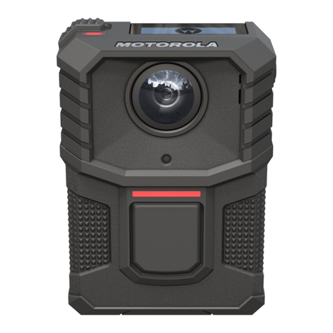
Motorola solutions V700 User manual

V700 Body-Worn Camera
User Guide
* MN009878A01*
MN009878A01-B
JUNE 2023
© 2023 Motorola Solutions, Inc. All rights reserved

Intellectual Property and Regulatory
Notices
Copyrights
The Motorola Solutions products described in this document may include copyrighted Motorola
Solutions computer programs. Laws in the United States and other countries preserve for Motorola
Solutions certain exclusive rights for copyrighted computer programs. Accordingly, any copyrighted
Motorola Solutions computer programs contained in the Motorola Solutions products described in this
document may not be copied or reproduced in any manner without the express written permission of
Motorola Solutions.
No part of this document may be reproduced, transmitted, stored in a retrieval system, or translated
into any language or computer language, in any form or by any means, without the prior written
permission of Motorola Solutions, Inc.
Trademarks
MOTOROLA, MOTO, MOTOROLA SOLUTIONS, and the Stylized M Logo are trademarks or
registered trademarks of Motorola Trademark Holdings, LLC and are used under license. All other
trademarks are the property of their respective owners.
WATCHGUARD and Evidence Library are trademarks or registered trademarks of WatchGuard Video,
Inc.
License Rights
The purchase of Motorola Solutions products shall not be deemed to grant either directly or by
implication, estoppel or otherwise, any license under the copyrights, patents or patent applications
of Motorola Solutions, except for the normal non-exclusive, royalty-free license to use that arises by
operation of law in the sale of a product.
Open Source Content
This product may contain Open Source software used under license. Open Source licenses, legal
notices, attribution, and corresponding open source software are available upon request.
European Union (EU) and United Kingdom (UK) Waste of Electrical and
Electronic Equipment (WEEE) Directive
The European Union's WEEE directive and the UK's WEEE regulation require that products sold
into EU countries and the UK must have the crossed-out wheelie bin label on the product (or the
package in some cases). As defined by the WEEE directive, this crossed-out wheelie bin label means
that customers and end-users in EU and UK countries should not dispose of electronic and electrical
equipment or accessories in household waste.
Customers or end-users in EU and UK countries should contact their local equipment supplier
representative or service centre for information about the waste collection system in their country.
Disclaimer
Please note that certain features, facilities, and capabilities described in this document may not be
applicable to or licensed for use on a specific system, or may be dependent upon the characteristics of
MN009878A01-B
Intellectual Property and Regulatory Notices
2

a specific mobile subscriber unit or configuration of certain parameters. Please refer to your Motorola
Solutions contact for further information.
© 2023 Motorola Solutions, Inc. All Rights Reserved
MN009878A01-B
Intellectual Property and Regulatory Notices
3

Contact Us
The Centralized Managed Support Operations (CMSO) is the primary contact for technical support
included in your organization's service agreement with Motorola Solutions.
Service agreement customers should be sure to call the CMSO in all situations listed under Customer
Responsibilities in their agreement, such as:
• To confirm troubleshooting results and analysis before taking action
Your organization received support phone numbers and other contact information appropriate for your
geographic region and service agreement. Use that contact information for the most efficient response.
However, if needed, you can also find general support contact information on the Motorola Solutions
website, by following these steps:
1Enter motorolasolutions.com in your browser.
2Ensure that your organization's country or region is displayed on the page. Clicking or tapping the
name of the region provides a way to change it.
3Select "Support" on the motorolasolutions.com page.
Comments
Send questions and comments regarding user documentation to
Provide the following information when reporting a documentation error:
• The document title and part number
• The page number or title of the section with the error
• A description of the error
Motorola Solutions offers various courses designed to assist in learning about the system. For
information, go to https://learning.motorolasolutions.com to view the current course offerings and
technology paths.
MN009878A01-B
Contact Us
4

Document History
Version Description Date
MN009878A01-002 V700 1.0.1 release May 2023
MN009878A01-001 Initial 1.0.0 release (GA) May 2023
MN009878A01-000 Initial beta release February 2023
MN009878A01-B
Document History
5

FCC ID AZ499FT7164
IC 109U-99FT7164
Motorola Solutions WiFi base contains the following IDs:
FCC ID YJV-VST500
The device complies with Part 15 of the FCC rules and Industry Canada license-exempt RSS
standards subject to the following two conditions:
1 The device may not cause harmful interference.
2 The device must accept all interference received, including interference that may cause undesired
operation.
Under Industry Canada regulations, this radio transmitter may only operate using an antenna of a type
and maximum (or lesser) gain approved for the transmitter by Industry Canada. To reduce potential
radio interference to other users, the antenna type and its gain should be so chosen that the equivalent
isotropically radiated power (e.i.r.p.) is not more than that necessary for successful communication.
Avertissements de la FCC et IC
Cet appareil est conforme à la Partie 15 des règlements de la FCC et Industrie Canada exempts de
licence standard RSS. Cet appareil doit être utilisé uniquement avec l'antenne fournie par Motorola
Solutions, Inc. Tout changement ou modification non expressément approuvée par le fabricant pourrait
. annuler l'autorité de l'utilisateur de faire fonctionner l'appareil
Motorola Solutions V700 se voit attribuer les identifiants suivants
FCC ID AZ499FT7164
Motorola Solutions WiFi base contient les identifiants suivants:
FCC ID YJV-VST500
Cet appareil est conforme à la Partie 15 des règlements de la FCC et Industrie Canada exempts de
licence standard RSS soumis aux deux conditions suivantes:
1Cet appareil ne peut causer des interférences nuisibles.
2Cet appareil doit accepter toutes les interférences reçues, y compris les interférences qui peuvent
perturber le fonctionnement.
Conformément à la réglementation d'Industrie Canada, cet émetteur radio ne peut fonctionner à l'aide
d'une antenne d'un type et maximum (ou moins) Gain approuvé pour l'émetteur par Industrie Canada.
Pour réduire le risque d'interférence avec d'autres utilisateurs, le type d'antenne et son gain doivent
être choisis afin que la puissance isotrope rayonnée équivalente (PIRE) ne dépasse pas ce qui est
nécessaire pour une communication réussie.
MN009878A01-B
FCC and IC Notices
FCC and IC Notices
FCC and IC Notices
This equipment complies with Part 15 of the FCC rules and Industry Canada license-exempt RSS
standards. This equipment should only be used with the antenna supplied by Motorola Solutions. Any
changes or modifications not expressly approved by the manufacturer could void the user's authority
. to operate the equipment
Motorola Solutions V700 is assigned the following IDs
6

Supplier's Declaration of Conformity
Declaration of Conformity
Per FCC CRF 47 Part 2 Section 2.1077(a)
Responsibility Party
Name: Motorola Solutions, Inc.
Address: 2000 Progress Pkwy, Schaumburg IL, 60196
Phone Number: 1-800-927-2744
Hereby declares that the product V700 conforms to the following regulations:
FCC Part 15, subpart B, section 15.107(a), 15.107(d), and section 15.09(a)
MN009878A01-B
Supplier's Declaration of Conformity
7

Class B Digital Device
As a personal computer peripheral, this device complies with Part 15 of the FCC Rules. Operation is
subject to the following two conditions:
• This device may not cause harmful interference, and
• This device must accept any interference received, including interference that may cause undesired
operation
NOTE: This equipment has been tested and found to comply with the limits for a Class B digital
device, pursuant to Part 15 of the FCC Rules. These limits are designed to provide reasonable
protection against harmful interference in a residential installation. This equipment generates,
uses and can radiate radio frequency energy and, if not installed and used in accordance with
the instructions, may cause harmful interference to radio communications. However, there is no
guarantee that interference will not occur in a particular installation.
If this equipment does cause harmful interference to radio or television reception, which can be
determined by turning the equipment off and on, the user is encouraged to try to correct the
interference by one of the following measures:
• Reorient or relocate the receiving antenna
• Increase the separation between the equipment and receiver
• Connect the equipment into an outlet on a circuit different from that to which the receiver is
connected
• Consult the dealer or an experienced radio/TV technician for help
NOTE: Transfer Station II has been tested and found to comply with the limits for Class A digital
device, pursuant part 15 of the FCC.
MN009878A01-B
Class B Digital Device
8

Important Safety Information
RF Energy Exposure Training and Product Safety Information for Mission Critical Devices.
NOTICE: ATTENTION! This mission critical device is restricted to Occupational use only.
Before using the mission critical device, read the RF Energy Exposure Training and Product
Safety Information for Mission Critical Devices manual which contains important operating
instructions for safe usage and RF energy awareness and control for Compliance with
applicable standards and Regulations. This equipment is designed and manufactured not to
exceed the emission limits for exposure to radio frequency (RF) energy set by the Federal
Communications Commission of the U.S. Government. For body worn operation, this device
has been tested and meets the FCC RF exposure guideline for use with a Motorola Solutions,
Inc. approved accessories sold with this device.
MN009878A01-B
Important Safety Information
9

Contents
Intellectual Property and Regulatory Notices.......................................................... 2
Contact Us................................................................................................................... 4
Document History....................................................................................................... 5
FCC and IC Notices.....................................................................................................6
Supplier's Declaration of Conformity .......................................................................7
Class B Digital Device................................................................................................ 8
Important Safety Information..................................................................................... 9
List of Figures............................................................................................................14
List of Tables............................................................................................................. 15
Chapter 1: Introduction...........................................................................................16
1.1 About the V700 Body-Worn Camera..................................................................................... 16
1.2 Related Documents and Information..................................................................................... 17
1.3 Prerequisites and Requirements........................................................................................... 17
Chapter 2: V700 During a Shift.............................................................................. 18
2.1 Power On and Off.................................................................................................................. 19
2.1.1 Powering On............................................................................................................ 19
2.1.2 Powering Off ........................................................................................................... 19
2.1.3 Forcing Power Off.................................................................................................... 19
2.2 Wearing the V700.................................................................................................................. 20
2.2.1 Mounting the Center Chest Mount........................................................................... 20
2.2.2 Mounting the Locking Molle Mount.......................................................................... 22
2.2.3 Mounting the Shirt Clip Mount..................................................................................23
2.2.4 Mounting the Jacket Clip Mount...............................................................................25
2.2.5 Mounting the Heavy Jacket Magnetic Mount........................................................... 27
2.2.6 Mounting the Belt/Strap Mount................................................................................ 28
2.3 Replacing the V700 Battery................................................................................................... 29
2.4 Battery Charge.......................................................................................................................29
2.4.1 Camera Charging Display........................................................................................30
2.4.2 Camera Shutting Down Due to Low Battery............................................................ 30
2.5 Assigning a Configuration and Checking Out........................................................................ 30
2.6 Associate a V700 with a Recording Group............................................................................ 30
2.7 Start and Stop Recorded Events........................................................................................... 31
2.7.1 Starting a Recorded Event Manually....................................................................... 31
2.7.2 Stopping a Recorded Event Manually......................................................................32
2.7.3 Categorizing a Recorded Event............................................................................... 32
MN009878A01-B
Contents
10
2.7.3.1 Event Categorization on the Camera in a Recording Group......................33
2.7.4 Work in Covert Mode............................................................................................... 33
2.7.4.1 Entering Covert Mode................................................................................ 33
2.7.4.2 Exiting Covert Mode...................................................................................33
2.7.4.3 Covert Mode Alert ..................................................................................... 34
2.7.5 Bookmark/Snapshot.................................................................................................34
2.8 Muting the V700.....................................................................................................................35
2.8.1 Continuous Mute......................................................................................................35
2.8.1.1 Enabling Continuous Mute......................................................................... 35
2.8.1.2 Disabling Continuous Mute........................................................................ 35
2.8.2 Muting Audio Momentarily....................................................................................... 35
2.9 Event Upload......................................................................................................................... 36
2.9.1 Monitor Event Uploading..........................................................................................36
2.9.1.1 Record-After-the-Fact (RATF) Events........................................................36
2.9.1.2 Clearing Video Out of Camera Storage..................................................... 36
2.10 V700 in a Recording Group................................................................................................. 37
2.10.1 Recording Group Overview....................................................................................37
2.10.2 Recording Group Members....................................................................................38
2.10.3 Group Events......................................................................................................... 40
2.11 Pre-Event and Record-After-the-Fact (RATF)..................................................................... 40
2.11.1 Pre-Event Capture................................................................................................. 41
2.11.1.1 Audio........................................................................................................ 41
2.11.2 Record-After-the-Fact (RATF)............................................................................... 41
2.11.2.1 Record-After-the-Fact (RATF) Event Generation.....................................41
2.11.2.2 Storage.....................................................................................................41
2.11.2.3 Audio........................................................................................................ 41
2.11.3 Force Microphone On............................................................................................ 42
2.12 APX Integration with V700...................................................................................................42
2.12.1 Pairing the V700 with an APX Radio .................................................................... 42
2.12.2 Emergency Record Trigger....................................................................................42
2.12.3 V700 and APX Radio Pairing Flow........................................................................ 43
2.12.3.1 Pairing the APX Radio with V700.............................................................43
2.12.3.2 Re-pair V700 and APX Radio Connection............................................... 45
2.12.3.3 Out-of-Range........................................................................................... 45
2.12.3.4 No Connection in the Field.......................................................................45
2.13 Holster Aware...................................................................................................................... 45
2.13.1 Connecting Yardarm Holster Aware...................................................................... 45
2.13.2 Holster Aware Status............................................................................................. 46
2.13.3 Sensor Battery Levels............................................................................................47
MN009878A01-B
Contents
11

2.14 V700 Docking Overview...................................................................................................... 47
2.14.1 Dock the V700 in a WiFi Base............................................................................... 48
2.14.2 Dock the V700 in a Transfer Station II................................................................... 49
2.14.3 Periodic Configuration Updates............................................................................. 50
2.15 USB Dock and Upload.........................................................................................................50
2.15.1 Upgrading the V700 Firmware............................................................................... 51
Chapter 3: V700 Overview...................................................................................... 52
3.1 V700 Key Features................................................................................................................ 52
3.2 V700 Configuration................................................................................................................ 53
3.3 V700 Display..........................................................................................................................54
3.3.1 Home Screen........................................................................................................... 56
3.3.2 Clearing Error Messages......................................................................................... 56
3.4 V700 Buttons......................................................................................................................... 56
3.4.1 Function Button........................................................................................................57
3.4.2 Display Backlight Button.......................................................................................... 57
3.4.3 Record Start/Stop Button......................................................................................... 58
3.4.4 Power Button .......................................................................................................... 58
3.5 Microphone............................................................................................................................ 58
3.6 V700 User-Replaceable Battery............................................................................................ 58
3.6.1 V700 Battery Maintenance.......................................................................................59
3.6.1.1 Random Reboot or Power Off....................................................................59
3.6.1.2 Low Battery Percentage Report................................................................. 59
3.6.1.3 Unresponsive Power On or Off.................................................................. 59
3.6.1.4 Battery and Camera Contamination Causes..............................................59
3.6.1.5 Cleaning the Battery and Camera..............................................................60
3.6.1.6 Repairing the Battery or Camera............................................................... 60
3.7 Feedback Indicators.............................................................................................................. 60
3.8 Video, Audio, and Subtitle Evidence......................................................................................61
3.9 Recording Reminder Alert..................................................................................................... 62
3.10 Periodic Configuration Updates........................................................................................... 62
3.11 Data and Video Encryption Support.................................................................................... 62
3.12 GPS..................................................................................................................................... 63
3.13 WiFi Base............................................................................................................................ 64
3.13.1 LED Icons.............................................................................................................. 65
3.13.2 WiFi Base LEDs.....................................................................................................67
3.13.3 WiFi Base Firmware Upgrade ...............................................................................68
3.13.3.1 Upgrading WiFi Base............................................................................... 68
Chapter 4: V700 Connection with CommandCentral Aware............................... 70
4.1 Live Streaming over LTE to CommandCentral Aware...........................................................70
MN009878A01-B
Contents
12

4.2 Location Sharing over LTE to CommandCentral Aware........................................................71
Chapter 5: SmartControl for Mobile...................................................................... 73
5.1 SmartControl Overview..........................................................................................................73
5.1.1 Downloading the SmartControl App.........................................................................73
5.2 SmartControl Enablement..................................................................................................... 74
5.2.1 Troubleshooting Android Connection Setting Issues............................................... 76
5.2.2 Troubleshooting iPhone Connection Setting Issues................................................ 76
5.3 Connecting SmartControl to aV700....................................................................................... 76
5.4 SmartControl Settings............................................................................................................78
5.5 Accessing Settings When Not Connected............................................................................. 79
5.6 iOS Previously Connected Device Connection Issue............................................................ 80
5.7 Setting SmartControl Officer Preferences............................................................................. 81
5.8 Categorizing an Event........................................................................................................... 81
5.9 Streaming Live Video.............................................................................................................84
5.10 V700 Low Battery................................................................................................................ 84
5.11 Starting a State Capture...................................................................................................... 85
Chapter 6: LTE Wireless Service........................................................................... 86
6.1 LTE Service Icons..................................................................................................................86
6.2 LTE Automatic Uploads......................................................................................................... 87
6.2.1 Uploading Events Automatically over LTE...............................................................87
6.3 Uploading Events Manually over LTE....................................................................................88
MN009878A01-B
Contents
13

List of Figures
Figure 1: V700 Power On and Off Button...............................................................................................19
Figure 2: Center Chest Mount................................................................................................................ 21
Figure 3: Locking Molle Mount............................................................................................................... 22
Figure 4: Shirt Clip Mount.......................................................................................................................24
Figure 5: Jacket Clip Mount....................................................................................................................26
Figure 6: Heavy Jacket Magnetic Mount................................................................................................ 27
Figure 7: Belt/Strap Mount......................................................................................................................28
Figure 8: Replacing the V700 Battery.....................................................................................................29
Figure 9: Transfer Station II....................................................................................................................49
Figure 10: V700 Components.................................................................................................................53
Figure 11: Home Screen........................................................................................................................ 54
Figure 12: SD Card and Battery............................................................................................................. 54
Figure 13: Scrolling through the Info Sequence..................................................................................... 55
Figure 14: Home Screen........................................................................................................................ 56
Figure 15: V700 Power On Button..........................................................................................................58
Figure 16: Camera and Battery Storage.................................................................................................63
Figure 17: Power LED Icons...................................................................................................................65
Figure 18: LEDs on the WiFi Base......................................................................................................... 67
Figure 19: SmartControl App for Android............................................................................................... 73
Figure 20: SmartControl App for iPhone or iPad.................................................................................... 74
Figure 21: Android Services Enablement............................................................................................... 74
Figure 22: iOS Services Enablement..................................................................................................... 75
Figure 23: Connecting to the V700.........................................................................................................77
Figure 24: Officer Preferences and Device Connection......................................................................... 78
Figure 25: iOS previously Connected Device Connection Issue............................................................ 80
Figure 26: Setting Officer Preferences................................................................................................... 81
Figure 27: Categorizing an Event........................................................................................................... 82
Figure 28: Automatic Tagging on Recording Stop..................................................................................83
Figure 29: Performing a State Capture...................................................................................................85
MN009878A01-B
List of Figures
14

List of Tables
Table 1: Center Chest Mount Items........................................................................................................21
Table 2: Shirt Clip Mount Items.............................................................................................................. 24
Table 3: Jacket Clip Mount Items........................................................................................................... 26
Table 4: Start/Stop recorded event options............................................................................................ 31
Table 5: Bookmark/Snapshot Screens................................................................................................... 34
Table 6: Tricolor LEDs on Transfer Station II......................................................................................... 37
Table 7: Sensor Battery Levels.............................................................................................................. 47
Table 8: Info Sequence Items.................................................................................................................55
Table 9: Home Screen Icons.................................................................................................................. 56
Table 10: V700 Buttons.......................................................................................................................... 57
Table 11: Camera and Battery Storage Items........................................................................................ 63
Table 12: Power LED Items....................................................................................................................65
Table 13: Power Led Indicators..............................................................................................................65
Table 14: Activity LED Indicators............................................................................................................66
Table 15: Transfer Station II Front LED Indicators................................................................................. 66
Table 16: LEDs on the WiFi Base Items.................................................................................................67
Table 17: LED and WiFi Base Status..................................................................................................... 67
Table 18: Network Activity LED.............................................................................................................. 68
Table 19: V700 CommandCentral Aware Icons..................................................................................... 70
Table 20: SmartControl Functionalities.................................................................................................. 73
Table 21: SmartControl Services Enablement Items..............................................................................75
Table 22: iOS Services Enablement Items.............................................................................................75
Table 23: LTE Service Icons.................................................................................................................. 86
Table 24: Event Upload Configurations..................................................................................................87
MN009878A01-B
List of Tables
15

Chapter 1
Introduction
Welcome to the V700 Body-Worn Camera User Guide. This guide is designed to walk you through the
basics of using your V700 to collect video and audio evidence.
NOTE: This user guide documents V700 features through firmware version 1.0.1.
About This Document
The V700 Body-Worn Camera User Guide provides instructions for using a V700 during your shift. For
more information on using a V700 during your shift, see V700 During a Shift on page 18.
This user guide includes information about the basic components and operations of V700. For more
information on the components and operations of your V700, see V700 Overview on page 52.
This user guide also includes information for the following features:
•V700 Connection with CommandCentral Aware on page 70
•LTE Wireless Service on page 86
•SmartControl for Mobile on page 73
The images in this document are representative of what you could see on your screen. They are meant
to serve as a guide.
NOTE: This document covers the basic use of V700. It is not a comprehensive manual for
every possible action or situation you could experience when using your V700. If you have a
question about your V700 that is not covered in this document, contact your Motorola Solutions
representative.
1.1
About the V700 Body-Worn Camera
The V700 Body-Worn Camera captures, processes, and stores video and audio evidence.
The V700 includes the following:
• Dual microphones (Microphone on page 58)
• Display screen (V700 Display on page 54)
• Buttons (V700 Buttons on page 56)
• Top Status LED
• User-replaceable battery (V700 User-Replaceable Battery on page 58)
• Storage capacity for V700 is 24-36 hours at max resolution and frame rate
• Ultra-wide dynamic range image sensor
The V700 connects to your agency evidence management system for provisioning and uploading
recorded events.
NOTE: For more information, see V700 During a Shift on page 18 and V700 Overview on
page 52.
MN009878A01-B
Chapter 1 : Introduction
16

1.2
Related Documents and Information
For subjects related to your V700 body-worn camera that are not covered by the V700 Body-Worn
Camera User Guide, see the following documents:
• M500 In-Car Video System User Guide
• V300 Body-Worn Camera User Guide
• Transfer Station II Quick Start User Guide
• 4RE® In-Car Video User Guide
1.3
Prerequisites and Requirements
Ensure that you complete the prerequisites and meet the requirements.
Prerequisites
• The V700 requires a second-generation transfer station, WiFi Base, and/or USB Base
NOTE: You can dock either the stand-alone battery in the bases or the camera and battery
together. Docking both allows you to charge and upload at the same time. However, docking
a spare battery allows you to have a second battery available when needed. The camera
and battery only dock in one direction.
• Transfer Station II provisions the V700 to your agency evidence management system
• USB upload requires that your Primary Domain Name is set in your agency evidence management
system and that you have an IP address set for the DNS Server Primary field
For more information, see USB Dock and Upload on page 50.
Reserved IP Addresses
V700 components require the following reserved IP addresses:
• 192.168.99.x (USB and WiFi Base)
• 192.168.98.x (SmartControl)
• 192.168.97.x (reserved for future use)
If you assign your in-car network any of these IP address ranges, you may have communication
issues.
Warning
WARNING: If the V700 is lost or there is any suspicion that it was tampered with, do not
connect the camera to your network or place it in a USB Base or WiFi Base. You should return
the camera to Motorola Solutions to download the evidence and perform a factory reset; this
ensures no damage is caused to the servers by malicious code placed on the camera.
MN009878A01-B
Chapter 1 : Introduction
17

Chapter 2
V700 During a Shift
The V700 Body-Worn Camera allows you to capture, process, and store video and audio evidence.
Your V700 connects to your agency evidence management system for provisioning and uploading
evidence.
The following sections provide you with instructions of common tasks that you need to perform on the
V700 throughout your shift:
Start of a Shift
•Powering On on page 19
•Wearing the V700 on page 20
•Replacing the V700 Battery on page 29
•Battery Charge on page 29
•Assigning a Configuration and Checking Out on page 30
During a Shift
•Associate a V700 with a Recording Group on page 30
•Start and Stop Recorded Events on page 31
•Muting the V700 on page 35
•Event Upload on page 36
•V700 in a Recording Group on page 37
•Pre-Event and Record-After-the-Fact (RATF) on page 40
•APX Integration with V700 on page 42
•Holster Aware on page 45
MN009878A01-B
Chapter 2 : V700 During a Shift
18

End of a Shift
•V700 Docking Overview on page 47
•USB Dock and Upload on page 50
•Powering Off on page 19
2.1
Power On and Off
To power the V700 on and off, you must use the Power button. The Power button is the oval shape on
the bottom of the V700 battery.
Figure 1: V700 Power On and Off Button
2.1.1
Powering On
Procedure:
On the bottom of the camera battery, press and release the Power button.
The camera goes through the booting and information sequences. When it is ready to use, the display
shows the number of events in storage and displays a solid green LED light on the top. Depending on
your agency configuration, the camera vibrates or plays an ascending tone sound.
2.1.2
Powering Off
Procedure:
1On the bottom of the camera, press and release the Power button.
2After the prompt, press the Power button again.
After you press the Power button the second time, the screen shows SHUTTING DOWN, and the green
LED turns off. Depending on your configuration, descending tones sound.
2.1.3
Forcing Power Off
WARNING: Avoid forcing the V700 to power off by abruptly removing the battery without going
through the shut down procedure above. Forcing the camera to power off can result in data
corruption.
MN009878A01-B
Chapter 2 : V700 During a Shift
19

If the V700 stops responding to commands, or if technical services instructs you to, you can force the
camera to power off.
Procedure:
To force the camera to power off, remove the battery.
The V700 may show System Recovery on the screen at the next boot.
NOTE: Allow the camera up to 10 minutes to complete the storage verification process.
2.2
Wearing the V700
The V700 can be mounted to your uniform using the following types of mounts:
• Center Chest Mount (Mounting the Center Chest Mount on page 20)
• Locking Molle Mount (Mounting the Locking Molle Mount on page 22)
• Shirt Clip Mount (Mounting the Shirt Clip Mount on page 23)
• Jacket Clip Mount (Mounting the Jacket Clip Mount on page 25)
• Heavy Jacket Magnetic Mount (Mounting the Heavy Jacket Magnetic Mount on page 27)
• Belt/Strap Mount (Mounting the Belt/Strap Mount on page 28)
WARNING: Potential Medical Device Interference.
This Center Chest Mount and the Heavy Jacket Mount incorporate very strong magnets. If you
are using a personal medical device, such as a pacemaker or other programmable medical
devices, talk to your health care provider, or consult the manufacturer of your device before
using these mounts. Determine if your personal medical device can be used in close proximity
to magnets. If in doubt, do not use the Center Chest or Heavy Jacket Mounts.
Talk to your health care provider if you are experiencing any symptoms or have questions
regarding magnets.
Also, be aware that magnets can damage other products, including cell phones, computers,
hard drives, and other electronic devices, as well as credit cards and magnetic media. Keep
these mounts away from any devices that can be affected by a magnetic field.
You should wear the V700 on your clothing and vest where it is most comfortable, convenient, and
secure. Ensure that the lens is not obstructed and that it is aimed at the horizon.
2.2.1
Mounting the Center Chest Mount
The center chest mount is made to fit over the buttons or zipper in the center of your chest. You
can also wear it over your pocket or on the protective vest or jacket. The magnets are strong with 65
pounds of pressure when snapped together.
When and where to use:
MN009878A01-B
Chapter 2 : V700 During a Shift
20
Table of contents
Other Motorola solutions Digital Camera manuals

Motorola solutions
Motorola solutions VT-100 User manual

Motorola solutions
Motorola solutions Avigilon 8.0C-H5A-FE-DO1 User manual

Motorola solutions
Motorola solutions L5Q User manual

Motorola solutions
Motorola solutions PELCO Sarix Multi Pro User manual

Motorola solutions
Motorola solutions L6Q User manual

Motorola solutions
Motorola solutions edesix VIDEOBADGE VB-400 User manual

Motorola solutions
Motorola solutions L6Q User manual

Motorola solutions
Motorola solutions edesix VIDEOBADGE VB-400 User manual

Motorola solutions
Motorola solutions V300 User manual

Motorola solutions
Motorola solutions edesix VIDEOBADGE VB-400 User manual