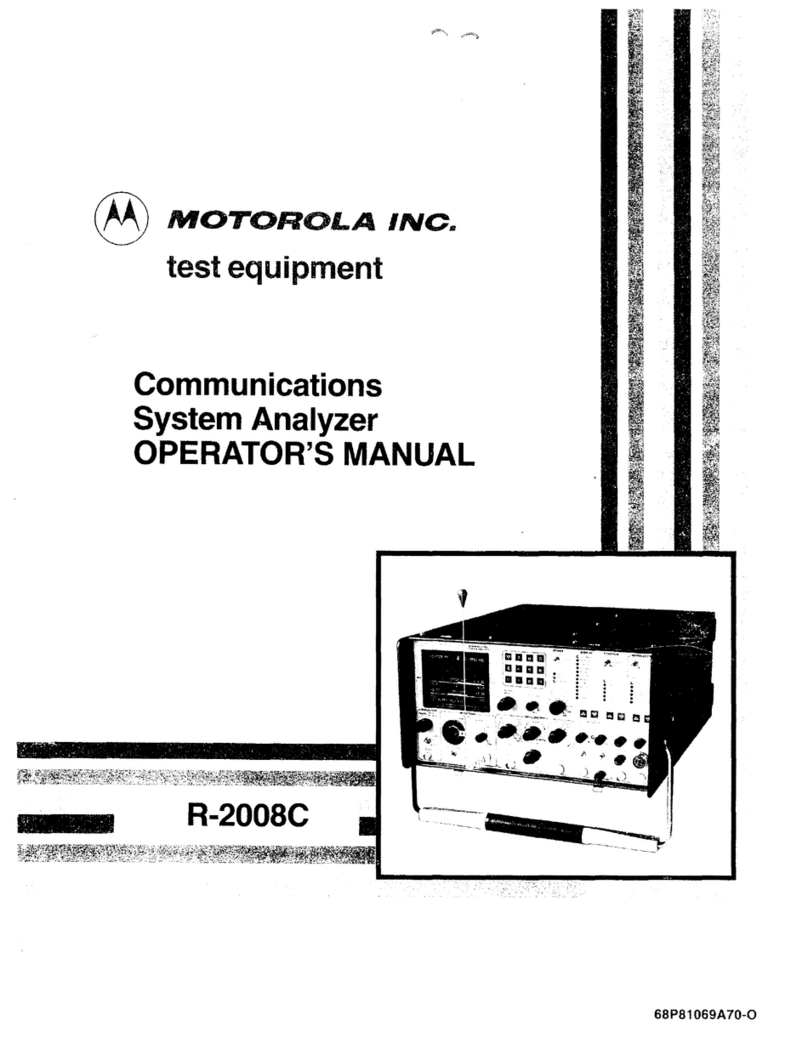
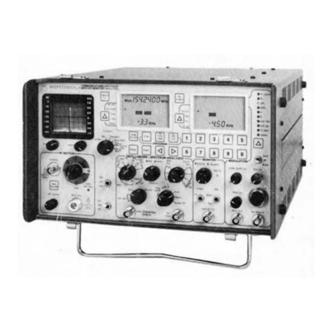
Motorola R-20010 User manual

@
MOTOROLA
Communications
Sector
...
J
..
,
~l
. . .
. J . J r 1• ]
'
scI
4 ' j •
..
•
•
•
•
•
•
•
..
•
..
tl
•
•
COMMUNICATIONS
SYSTEM ANALYZER R-20010
Motorola, Inc. I
'.188
All R
ig
ht Rc
crvc:d
Printed in U
..
A.
Maintenance Manual
t1i\
Motorola Test
'f.:)} EquipmentProducts
1313 E. Algonquin Rd.
Schaumburg, IL 60196 RLN4073A
12/l
m6-PH
I

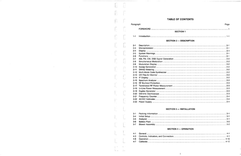
TABLE OF CONTENTS
Paragraph Page
1.1
1.2
FOREWORD
SECTION
1.
INTRODUCTION
DESCRIPTION
.....
. .
...
. .
.......
......
..
.....
.
..
..
..
..
....
.
..............
.
MAJOR ASSEMBLIES .
......
.
......
...
..
....
...
.
.........
. . .
..
..
...........
.
SECTION
2.
SYSTEM THEORY OF OPERATION
1-1
1-8
2.1 DESCRIPTION . . . . . . . . . . . . . . . . . . . . . . . . . . . . . . . . . . . . . . . . . . . . . . . . . . . . . . . . . . . . . 2-1
2.2 SYSTEM CONTROL
...
......................
...
.......
...
. . .
.....
. .
.........
2-1
2.2.1 Processor. . . . . . . . . . . . . . . . . . . . . . . . . . . . . . . . . . . . . . . . . . . . . . . . . . . . . . . . . .
2-1
2.2.2 Process
or
Bus . . . . . . . . . . . . . . . . . . . . . . . . . . . . . . . . . . . . . . . . . . . . . . . . . . . . . .
2-1
2.2.3 Control Busses . . . . . . . . . . . . . . . . . . . . . . . . . . . . . . . . . . . . . . . . . . . . . . . . . . . . . . 2-1
2.2.4 IEEE Bus . . . . . . . . . . . . . . . . . . . . . . . . . . . . . . . . . . . . . . . . . . . . . . . . . . . . . . . . . . 2-3
2.3 GENERATE MODE . . . . . . . . . . . . . . . . . . . . . . . . . . . . . . . . . . . . . . . . . . . . . . . . . . . . . . . . . . 2-3
2.3.1 General . . . . . . . . . . . . . . . . . . . . . . . . . . . . . . . . . . . . . . . . . . . . . . . . . . . . . . . . . . . 2-3
2.3.2 Frequency Standard . . . . . . . . . . . . . . . . . . . . . . . . . . . . . . . . . . . . . . . . . . . . . . . . . . 2-4
2.3.3
RF
Synthesizer . . . . . . . . . . . . . . . . . . . . . . . . . . . . . . . . . . . . . . . . . . . . . . . . . . . . . . 2-4
2.3.4 Wideband Amplifier . . . . . . . . . . . . . . . . . . . . . . . . . . . . . . . . . . . . . . . . . . . . . . . . . . . 2-4
2.3.5 Step Attenuator . . . . . . . . . . . . . . . . . . . . . . . . . . . . . . . . . . . . . . . . . . . . . . . . . . . . . 2-4
2.3.6 Input/Output. . . . . . . . . . . . . . . . . . . . . . . . . . . . . . . . . . . . . . . . . . . . . . . . . . . . . . . . 2-4
2.4 WATTMETER. . . . . . . . . . . . . . . . . . . . . . . . . . . . . . . . . . . . . . . . . . . . . . . . . . . . . . . . . . . . . . 2-4
2.5 MONITOR MODE . . . . . . . . . . . . . . . . . . . . . . . . . . . . . . . . . . . . . . . . . . . . . . . . . . . . . . . . . . . 2-5
2.5.1 General . . . . . . . . . . . . . . . . . . . . . . . . . . . . . . . . . . . . . . . . . . . . . . . . . . . . . . . . . . . 2-5
2.5.2
RF
Input. . . . . . . . . . . . . . . . . . . . . . . . . . . . . . . . . . . . . . . . . . . . . . . . . . . . . . . . . . . 2-5
2.5.3 Receiver. . . . . . . . . . . . . . . . . . . . . . . . . . . . . . . . . . . . . . . . . . . . . . . . . . . . . . . . . . . 2-5
2.6 DUPLEX GENERATOR (STANDARD AND ENHANCED)
....
.
.........
.
................
2-6
2.7 CODE SYNTHESIZER . . . . . . . . . . . . . . . . . . . . . . . . . . . . . . . . . . . . . . . . . . . . . . . . . . . . . . . 2-6
2.8 FREQUENCY COUNTER . . . . . . . . . . . . . . . . . . . . . . . . . . . . . . . . . . . . . . . . . . . . . . . . . . . . . 2
-7
2.9 DIGITAL VOLTMETER (DVM) . . . . . . . . . . . . . . . . . . . . . . . . . . . . . . . . . . . . . . . . . . . . . . . . . . 2-7
2.10 DISTORTION/SINAD METER . . . . . . . . . . . . . . . . . . . . . . . . . . . . . . . . . . . . . . . . . . . . . . . . . . 2-8
2.
11
OSCILLOSCOPE . . . . . . . . . . . . . . . . . . . . . . . . . . . . . . . . . . . . . . . . . . . . . . . . . . . . . . . . . . . 2-8
3.1
3.2
SECTION 3. ALIGNMENT PROCEDURE
INTRODUCTION
....
.
...
......
.
...
..
..........
.
...
..
...
..
.
.................
.
3.1.1 Test Equipment Required
......
..
.....
.
........
.
.....
.
...
.
..
..
...
.
....
.
3.1.2 Preparationfor Alignment
.............
....
.
........
..
...
...
....
. .
..
...
.
BASIC ALIGNMENT PROCEDURE
..
...
.
......
. . . .
..
. .
......
. . .
..
..
......
.
...
. . .
3.2.1 Low Voltage Supply
..........
.......
..........
....
.
...
.....
.........
.
3.2.2 CRT Intensity Bias
..
. .
.....
...
.
...
..
....
.........
. . .
...
....
. .
.......
.
3.2.3 CRT Intensity Balance
........
.
..
.
.....
.
..
.......
..
.......
......
..
.
...
.
3.2.4 CRT Astigmatism and Geometry . .
..
..
..
. . .
................
...
. .
..
.
....
·
~
·
3.2.5 CRT Vertical Centering and Trace Rotation
................
........
...
:
....
:.
3.2.6 CRT Horizontal Centering
.....
.
..
.
..
...
.....
..
.................
·.
......
.
3.2.7 CRT Horizontal Gain
......
.
....
........................
...
...
..
......
.
3.2.8 CRT Vertical Gain .
....
. . .
......
.
...
.......
..
.............
...
........
.
3.2.9 Vertical Input Gain.
....
..
.........
....
......
......
...
.
...........
.
...
.
3.2.1
0 DVM Zero
.......
.
........
.
......
..
...
......
.
....
.................
.
3.2.
11
Character Generator
....
. .
.....
....
......
. . .
......
.
.....
.
............
.
3.2.12 Spectrum Analyzer Centering
...................
.....
...
. .
....
.
..
.....
..
.
3.2.13 Horizontal Timebase
..
...
.
........................
...
..
.
...
..
....
. .
..
.
3-1
3-1
3-1
3-1
3-1
3-1
3-1
3-3
3
-3
3-3
3-3
3-4
3-4
3
-5
3-5
3-5
3
-6

TABLE OF CONTENTS (Cont)
Paragraph Page
3.3 EXTENDED
ALIGNMENT
PROCEDURE . . . . . . . . . . . . . . . . . . . . . . . . . . . . . . . . . . . . . . . . . .
3-6
4.1
4.2
4.3
6.1
6.2
7.1
7.2
8.1
8.2
3.3.1
DVM
. . . . . . . . . . . . . . . . . . . . . . . . . . . . . . . . . . . . . . . . . . . . . . . . . . . . . . . . . . . . . 3-6
3.3.2 Distortion/SINAD Alignment. . . . . . . . . . . . . . . . . . . . . . . . . . . . . . . . . . . . . . . . . . . . .
3-8
3.3.3 Receiver. . . . . . . . . . . . . . . . . . . . . . . . . . . . . . . . . . . . . . . . . . . . . . . . . . . . . . . . . . .
3-8
3.
3A
RF Synthesizer. . . . . . . . . . . . . . . . . . . . . . . . . . . . . . . . . . . . . . . . . . . . . . . . . . . . . . 3-9
3.3.5 Frequency Standard . . . . . . . . . . . . . . . . . . . . . . . . . . . . . . . . . . . . . . . . . . . . . . . . . . 3-1
0
3.3.6 Duplex Generators . . . . . . . . . . . . . . . . . . . . . . . . . . . . . . . . . . . . . . . . . . . . . . . . . . . 3-11
3.3.7 Wideband Amplifier . . . . . . . . . . . . . . . . . . . . . . . . . . . . . . . . . . . . . . . . . . . . . . . . . . . 3-11
3.3.8
Wattmeter
. . . . . . . . . . . . . . . . . . . . . . . . . . . . . . . . . . . . . . . . . . . . . . . . . . . . . . . . . 3-
19
3.3.9
Scope
Compensation . . . . . . . . . . . . . . . . . . . . . . . . . . . . . . . . . . . . . . . . . . . . . . . . . 3-19
3.3
.10
Cathode
Voltage. . . . . . . . . . . . . . . . . . . . . . . . . . . . . . . . . . . . . . . . . . . . . . . . . . . . . 3-
19
SECTION 4.
SYSTEM
CHECKOUT AND TROUBLESHOOTING
INTRODUCTION
....
.
.....
. . .
..
....
....
..
......
..
.
...............
.......
...
.
SAFE HANDLING
OF
CMOS
INTEGRATED-CIRCUITS DEVICES
..
. .
...................
.
CHECKOUT
AND
TROUBLESHOOTING PROCEDURES . .
.....
....
.
........
.........
.
SECTION
5.
SYSTEM WIRELIST AND PARTS
LIST-
SYSTEM
MOTHERBOARD
(A19)
. (See LIST
OF
TABLES)
SECTION 6. HIGH-VOLTAGE POWER SUPPLY (A1)
DESCRIPTION . .
..........
........
. .
............
.
....................
.
...
. .
THEORY
OF
OPERATION
...
...
................
..
....
.
..
.
....
. .
...
.
...
.......
.
6.2.1 Voltage Regulation Circuit
.. ..
..
..
...................
.
....
.....
........
.
6.2.2 Multipliers
......
..
....
.
....
.
..
....
...
...
.
..
..
....
........
.
......
.
..
.
6.2.3 Intensity
Modulator
..............
..
....................
.
.............
.
6.
2.4
Focus
Modulator
. .
.......
.
....
....
.
...
..
........
.
....
.....
.
.........
.
6.2.5 Transient Protector(A1A2)
.......
.
........
.
.........
.
........
. .
.....
..
.
SECTION 7. SCOPE AMPLIFIER BOARD
(A2)
DESCRIPTION . . . . .
.........
.
........................
.
.........
.....
.....
. .
THEORY OF OPERATION
....
. . .
..................
.
......
..
. . . .
.........
.
....
.
7.2.1 Deflection Amplifiers
.................
. . .
....
..
...
. . .
.................
.
7.2.2
Hor
izontal Timebase Generator
...
..
.....
....
..
..
..
. . . .
..
. .
..
..
...
....
..
.
7.2.3 Horizontal Switching
..
.
...
.. ..
....
......
...
.
.....
. .
..
........
....
..
. . .
7.2.4 Z-Axis
Modulator
.
..
...
...
.
...
..
...............
. . .
..
..
...
. .
......
. . . .
7.2.5 Intensity Control
..
.....
..
.
..
...
.......
..
......
.
....
.
............
.
...
.
7.2.6 Focus Control . . . . . . . . . . . . . . . . . . . . . . . . . . . . . . . . . . . . . . . . . . . . . . . . . . . . . . .
7.2.7
Ast
i
gmatism
. Geometry, and Trace Rotation . .
.......
...
. . . .
...............
. .
SECTION 8. LOW-VOLTAGE POWER SUPPLY
(A3-A6)
DESCRIPTION
........
..
....
. . .
..
...
...
...........
.
.........
....
..
..
....
. . .
THEORY OF OPERATION
........................
..
...
....
..
.
....
........
. .
..
.
8.2.1
Battery
Charger Board (A3) .
......
...
..
.
.......
.
..
....
.
......
.....
..
...
.
8.2.2 Control
Board
(A4)
......
..
..
.....
....
..
............
.
.......
....
..
.
..
.
8.2.3
Output
Board
(AS)
. .
..
...
.
....
...
.....
......
...
..
........
. .
......
. . . . .
8.2.4
Switcher
Board
(A6)
....
. .
..
.
........................
..
....
.
.........
.
8.2.5 Rear Panel
.....................................
.
..
.
...
.
.....
. . .
..
. .
ii
4-1
4-1
4-2
6-1
6-1
6-1
6-1
6-1
6-1
6-1
7-1
7-1
7-1
7-1
7-1
7-1
7-2
7-2
7-2
8-1
8-1
8-1
8-1
8-3
8-4
8-4

TABLE OF CONTENTS (Cont)
Paragraph Page
9.1
9.2
SECTION 9. SCOPE/DVM CONTROL BOARD {A7)
DESCRIPTION
...
..
.....
...
...
.
.....
. .
..
...
. . .
.....
..
.....
. .
..
. .
...
..
.
....
.
THEORY OF OPERATION.
..
.........
.
........
..
........
.
..
.
..
.
........
.
....
. .
9.2.1 Scope Vertical Control. . . . . . . . . . . . . . . . . . . . . . . . . . . . . . . . . . . . . . . . . . . . . . . . .
9.2.2 Dual-Display Control . .
..........
.
......
.
........
.
.......
.. .. ..
....
.
..
.
9.2.3 Scope Horizontal Control. .
...........
.
..
.
....
.
.........
. . .
..
.
..
.
......
.
9.2.4 Synthesizer Sweep Control
.............
. .
..........
.
..
.
...
.
...
.
...
. . . . .
9.2.5 Scope Z-Axis Control
....
.. ..
...
..
.
......
.
..
.
..................
. .
.. ..
.
9.2.6 Modulation-Display Control
...
................
.
.........
.
......
.
..
...
..
.
9.2.7 Peak Detector. . . . . . . . . . . . . . . . . . . . . . . . . . . . . . . . . . . . . . . . . . . . . . . . . . . . . . .
9.2.8 DVM Control .
.....
..
.
....
.
....
.
...
.
..
. . . .
..
...
.
...
.
...
............
.
9.2.9 External DVM/Distortion Control
..
. . . . . .
..
..
...
. . . .
...
. . .
..
.
..
.
..
. . . . .
..
.
9.2.1
0 Distortion Measurement
.....
. . . .
...
.
....
.
.............
.
..
.
..
. .
....
.
..
.
9.2.
11
External DVM Measurement
..
.
...
.
....
.
.....
. .
...
.
...
..
.......
.
.......
.
9.2.12 Audio Amplifier and Alarm Generator . .
..
.
....
.
...
.
..........
.
...
.
........
.
9.2.13 Board Control
..
. .
..
...
..
.
..
....
.
.. .. ..
.
..........
.
.....
. .
..
. .
...
.
..
.
SECTION 10. RECEIVER BOARD {AS)
9-1
9-1
9-t
9-1
9-1
9-2
9-2
9-2
9-2
9-2
9-3
9-3
9-3
9-3
9-3
10.1 DESCRIPTION
....
.
..
. . .
.....
. .
....
........
...
....
.
.......
..
..
...
..
.
.....
..
10-1
10.2 THEORY OF OPERATION.
..
....
. . .
..
. . . . . . . . . . . . . . . . . . . . . . . . . . . . . . . . . . . . . . . . . 10-1
10.2.1 Linear
IF
Section. . . . . . . . . . . . . . . . . . . . . . . . . . . . . . . . . . . . . . . . . . . . . . . . . . . . .
10-1
10.2.2 Logarithmic Amplifier. . . . . . . . . . . . . . . . . . . . . . . . . . . . . . . . . . . . . . . . . . . . . . . . . . 10-2
10.2.3
FM
/SSB/WB Signal-Present Detectors. . . . . . . . . . . . . . . . . . . . . . . . . . . . . . . . . . . . . 10-3
10.2.4 Baseband Audio-Processing Circuits . . . . . . . . . . . . . . . . . . . . . . . . . . . . . . . . . . . . . . 10-4
10.2.5 Digital Control and Power Conditioning . . . . . . . . . . . . . . . . . . . . . . . . . . . . . . . . . . . . . 10-4
SECTION 11. RF SYNTHESIZER MODULE (A9)
11
.1
DESCRIPTION . . . . . . . . . . . . . . . . . . . . . . . . . . . . . . . . . . . . . . . . . . . . . . . . . . . . . . . . . . . . .
11-1
11
.2 THEORYOFOPERATION
...
.
..
.
..
. .
..
...
..
.......
.
..
.
..
. .
....
....
..
.
..
. .
..
. . .
11
-1
11
.2.1 Reference and Control Board (A9A
1)
. . . . . . . . . . . . . . . . . . . . . . . . . . . . . . . . . . . . . .
11
-1
11
.2.2 310 to 440-MHz Loop Board (A9A2). . . . . . . . . . . . . . . . . . . . . . . . . . . . . . . . . . . . . . .
11
-2
11
.2.3 Output Board (A9A3). . . . . . . . . . . . . . . . . . . . . . . . . . . . . . . . . . . . . . . . . . . . . . . . . . 11-2
11
.2.4 60.5-MHz Loop Boa'
rd
(A9A4) . . . . . . . . . . . . . . . . . . . . . . . . . . . . . . . . . . . . . . . . . . .
11
-3
11
.2.5 GHz Loop Board (A9A5) . . . . . . . . . . . . . . . . . . . . . . . . . . . . . . . . . . . . . . . . . . . . . . .
11
-3
11.2.6 640-MHz Loop Board (A9A6) . . . . . . . . . . . . . . . . . . . . . . . . . . . . . . . . . . . . . . . . . . . .
11
-4
11
.3 SYNTHESIZER MOTHERBOARD (A9A7)
....
. . . . . . . . . . . . . . . . . . . . . . . . . . . . . . . . . . . . . .
11
-5
SECTION
12
. AUDIO SYNTHESIZER BOARD (A10)
12.1 DESCRIPTION
....
. .
.....
.
... ...
.....
.
..
.
...
.
......
.
..
..
.
.....
..
......
..
...
12-1
12.2 THEORY OF OPERATION. . . . . . . . . . . . . . . . . . . . . . . . . . . . . . . . . . . . . . . . . . . . . . . . . . . . . 12-1
12.2.1 Audio Synthesizer. . . . . . . . . . . . . . . . . . . . . . . . . . . . . . . . . . . . . . . . . . . . . . . . . . . . 12-1
12.2.2 DPL Generator . . . . . . . . . . . . . . . . . . . . . . . . . . . . . . . . . . . . . . . . . . . . . . . . . . . . . . 12-1
12
.2.3 1-kHz Tone.
...
.
......
.
..
.
.........
. . .
..
..
.
....
.
...........
.
...
..
. . . 12-2
12.2.4 Internal Modulation . . . . . . . . . . . . . . . . . . . . . . . . . . . . . . . . . . . . . . . . . . . . . . . . . . . 12-2
12
.2.5 External Modulation . . . . . . . . . . . . . . . . . . . . . . . . . . . . . . . . . . . . . . . . . . . . . . . . . . 12-2
12.2.6 Modulation Control . . . . . . . . . . . . . . . . . . . . . . . . . . . . . . . . . . . . . . . . . . . . . . . . . . . 12-2
12.2.7 Board Control. . . . . . . . . . . . . . . . . . . . . . . . . . . . . . . . . . . . . . . . . . . . . . . . . . . . . . . 12-2
iii

TABLE
OF
CONTENTS (Cont)
Paragraph
Page
SECTION 13. PROCESSOR INTERFACE BOARD (A11)
13.1 DESCRIPTION .
.....
.
.. ..
..
. . . . . . . . . . . . . . . . . . . . . . . . . . . . . . . . . . . . . . . . . . . . . . . . 13-1
13.2 THEORYOFOPERATION
...........
.....................
..
.......
..
....
..
.
..
.
13-1
13.
2.1
System Control-Bus Interface . . . . . . . . . . . . . . . . . . . . . . . . . . . . . . . . . . . . . . . . . . .
13-1
13.2.2 Digital Voltmeter (DVM) . . . . . . . . . . . . . . . . . . . . . . . . . . . . . . . . . . . . . . . . . . . . . . . . 13-1
13.2.3 Frequency Counter . . . . . . . . . . . . . . . . . . . . . . . . . . . . . . . . . . . . . . . . . . . . . . . . . . . 13-2
13
.2.
4 Board Control. . . . . . . . . . . . . . . . . . . . . . . . . . . . . . . . . . . . . . . . . . . . . . . . . . . . . . . 13-3
SECTION 14. PROCESSOR BOARD
(A
14)
PART 1. 01-P22140E001
14.1 DESCRIPTION
...
.
....
.
....
.
...
.....
...
...
. .
....
.
..
...
..
. . . . . . . . . . . . . . . . . . .
14-1
14.2 THEORY OF OPERATION
..
..
. . . . . . . . . . . . . . . . . . . . . . . . . . . . . . . . . . . . . . . . . . . . . . . . .
14-1
14.2.1 Microprocessor.
....
.
.....
..
....
.
.....
...
. .
...
. . . . . . . . . . . . . . . . . . . . . . .
14-1
14.2.2 Memory
...
. . . . . . . . . . . . . . . . . . . . . . . . . . . . . . . . . . . . . . . . . . . . . . . . . . . . . . . . 14-1
14.2.3 Input/Output. . . . . . . . . . . . . . . . . . . . . . . . . . . . . . . . . . . . . . . . . . . . . . . . . . . . . . . . 14-2
14.2.4 Character Display . . . . . . . . . . . . . . . . . . . . . . . . . . . . . . . . . . . . . . . . . . . . . . . . . . . . 14-2
PART2. 01-P29050H001
14.3 DESCRIPTION
.......
. .
...
. . . . . . . . . . . . . . . . . . . . . . . . . . . . . . . . . . . . . . . . . . . . . . . . . 14-3
14.4 THEORY
OF
OPERATION
..
.
..
..
...
.
....
..........
..
.....
..
.
..
....
.. ..
.
...
. . . . 14-3
14.4.1 Microprocessor. . . . . . . . . . . . . . . . . . . . . . . . . . . . . . . . . . . . . . . . . . . . . . . . . . . . . . 14-3
14.4.2 Memory . . . . . . . . . . . . . . . . . . . . . . . . . . . . . . . . . . . . . . . . . . . . . . . . . . . . . . . . . . . 14-3
14.4.3 Input/Output. . . . . . . . . . . . . . . . . . . . . . . . . . . . . . . . . . . . . . . . . . . . . . . . . . . . . . . . 14-3
14.4.4 Character Display . . . . . . . . . . . . . . . . . . . . . . . . . . . . . . . . . . . . . . . . . . . . . . . . . . . . 14-4
14.4.5 DTMF Encode/Decode . . . . . . . . . . . . . . . . . . . . . . . . . . . . . . . . . . . . . . . . . . . . . . . . 14-4
14.4.6 Printer Port. . . . . . . . . . . . . . . . . . . . . . . . . . . . . . . . . . . . . . . . . . . . . . . . . . . . . . . . . 14-4
SECTION 15. FRONT-PANEL INTERFACE BOARD (A15)
15
.1 DESCRIPTION
....
...
.................
.
.........
.
...............
. . .
.. ..
....
15-1
15.2 THEORY
OF
OP
ERAT
ION
.
.......................
...
.......
....
..
...
.
......
. . . 15-1
15.2.1 Processor-Control Interface. . . . . . . . . . . . . . . . . . . . . . . . . . . . . . . . . . . . . . . . . . . . . 15-1
15.2.2 Analog Interface .
...
..
. . . . . . . . . . . . . . . . . . . . . . . . . . . . . . . . . . . . . . . . . . . . . . . 15-5
SECTION 16. FREQUENCY-STANDARD INTERF-ACE BOARD (A16)
16.1 DESCRIPTION . . . . . . . . . . . . . . . . . . . . . . . . . . . . . . . . . . . . . . . . . . . . . . . . . . . . . . . . . . . . . 16-1
16.2 THEORY OF OPERATION
..............
. . . . . . . . . . . . . . . . . . . . . . . . . . . . . . . . . . . . . . . 16-1
16.2.1 Internal Source . . . . . . . . . . . . . . . . . . . . . . . . . . . . . . . . . . . . . . . . . . . . . . . . . . . . . . 16-1
16.2.2 External Source . . . . . . . . . . . . . . . . . . . . . . . . . . . . . . . . . . . . . . . . . . . . . . . . . . . . . 16-1
SECTION 17. RF INPUT MODULE (A17)
17.1 DESCRIPTION
..
..
. . . . . . . . . . . . . . . . . . . . . . . . . . . . . . . . . . . . . . . . . . . . . . . . . . . . . . . . . 17-1
17.2 THEORY
OF
OP
ER
ATION. . . .
..
........
.
...
. . . . . . . . . . . . . . . . . . . . . . . . . . . . . . . . . . .
17-1
17.2.1 Wattmeter Board (A17A1)
...........
. . . . . . . . . . . . . . . . . . . . . . . . . . . . . . . . . . . 17-1
17.2.2 Wideband Amplifier Board (A17A2)
..
...
. . . . . . . . . . . . . . . . . . . . . . . . . . . . . . . . . . . 17-2
17.2.3 Duplex Generator Board (A17A3) . . . . . . . . . . . . . . . . . . . . . . . . . . . . . . . . . . . . . . . . . 17-3
17.2.4 Enhanced Duplex Generator Board
(A1
7A3)
..
....
.
...
..
. . . . . . . . . . . . . . . . . . . . . 17-5
SECTION 18. FRONT PANEL ASSEMBLY (A18)
18.1 D
ESC
RIPTION . . . . . . . . . . . . . . . . . . . . . . . . . . . . . . . . . . . . . . . . . . . . . . . . . . . . . . . . . . . . . 18-1
18.2 CONTROLS, S
WI
TC
H
ES
AND
L
EOs
. . . . . . . . . . . . . . . . . . . . . . . . . . . . . . . . . . . . . . . . . . . . . 18-1
18.3
DECODING
FOR
DISPLAY,
FU
NCTION
AND
MODULATION
LEO
s.
......................
18-4
iv

TABLE OF CONTENTS (Cont)
Paragraph
Page
SECTION 19. BATTERY ASSEMBLY
19.1 DESCRIPTION .
..
......
. . . . . .
.. ..
.
..
.
...
. .
....
.
..
. .
..
...
. . .
....
.
..
.
...
. . .
..
19-1
19.2 INSTALLATION . . . . . . . . . . . . . . . . . . . . . . . . . . . . . . . . . . . . . . . . . . . . . . . . . . . . . . . . . . . .
19
-1
19.3
OP
E
RATION
. . . . . . . . . . . . . . . . . . . . . . . . . . . . . . . . . . . . . . . . . . . . . . . . . . . . . . . . . . . . . . 19-2
SECTION
20.
CELLULAR TELEPHONE TEST
OPTION
20.1 DESCRIPTION .
..
....
.
....
.........
. .
..
. . . .
....
.
....
. .
..
.
.......
. . .
....
....
20-1
20.2 THEORY
OF
OPERATION
. . .
.. ..
.
..
.
.....
. . . . . . . . . . . . .
...
. . .
..
. .
..
..
.
..
...
....
20-1
20.2.1 Transmitted Data . . . . . . . . . . . . . . . . . . . . . . . . . . . . . . . . . . . . . . . . . . . . . . . . . . . .
20
-1
20.2.2
Received
Data . . . . . . . . . . . . . . . . . . . . . . . . . . . . . . . . . . . . . . . . . . . . . . . . . . . . . .
20-1
20.2.3 Control. . . . . . . . . . . . . . . . . . . . . . . . . . . . . . . . . . . . . . . . . . . . . . . . . . . . . . . . . . . .
20-1
20.2.4 Modulati
on
. . . . . . . . . . . . . . . . . . . . . . . . . . . . . . . . . . . . . . . . . . . . . . . . . . . . . . . . .
20-1
20.2.5 10-
KHz
Detection . . . . . . . . . . . . . . . . . . . . . . . . . . . . . . . . . . . . . . . . . . . . . . . . . . . . 20-1
20.2.6 Manual-Mode Control . . . . . . . . . . . . . . . . . . . . . . . . . . . . . . . . . . . . . . . . . . . . . . . . . 20-1
SECTION
21. IEEE/REMOTE INTERFACE OPTION
PART 1. IEEE INTERFACE
21
.1 DESCRIPTION . . . . . . . . . . . . . . . . . . . . . . . . . . . . . . . . . . . . . . . . . . . . . . . . . . . . . . . . . . . . .
21
-1
21.2 THEORY
OF
OPERATION
..
...
..
.
.......
.
....
..
. .
..
...
. .
.....
.
..
.
...
..
.
.......
21
-1
21
.2.1
IEEE
Bus Interface . . . . . . . . . . . . . . . . . . . . . . . . . . . . . . . . . . . . . . . . . . . . . . . . . . .
21
-1
21.2.2
RF-Level
Control. . . . . . . . . . . . . . . . . . . . . . . . . . . . . . . . . . . . . . . . . . . . . . . . . . . . .
21-1
21
.2.3 Modulation Control . . . . . . . . . . . . . . . . . . . . . . . . . . . . . . . . . . . . . . . . . . . . . . . . . . .
21
-1
21
.2.4 Address-Decode
and
Control-Latch Circuitry. . . . . . . . . . . . . . . . . . . . . . . . . . . . . . . . .
21
-1
21
.2.5 Multipurpose Input/Output
and
Relay Ports. . . . . . . . . . . . . . . . . . . . . . . . . . . . . . . . . .
21-1
PART2. REMOTEINTERFACE
21.3 DESCRIPTION . . . . . . . . . . . . . . . . . . . . . . . . . . . . . . . . . . . . . . . . . . . . . . . . . . . . . . . . . . . . .
21
-2
21.4 THEORY
OF
OPERATION
.....
. .
...
.
..
.
...
.
..
. . . . . . .
...
.
...
.
..
..........
.
....
.
21
-2
21
.4.1
IEEE
Bus Interface . . . . . . . . . . . . . . . . . . . . . . . . . . . . . . . . . . . . . . . . . . . . . . . . . . .
21
-2
21.4.2
RS
-232 Bus Interface . . . . . . . . . . . . . . . . . . . . . . . . . . . . . . . . . . . . . . . . . . . . . . . . .
21
-2
21.4.3
RF
-
Level
Control. . . . . . . . . . . . . . . . . . . . . . . . . . . . . . . . . . . . . . . . . . . . . . . . . . . .
21
-2
21
.4.4 Modulation Control . . . . . . . . . . . . . . . . . . . . . . . . . . . . . . . . . . . . . . . . . . . . . . . . . . .
21
-2
21.4.5 Address-Decode
and
Control-Latch Circuitry. . . . . . . . . . . . . . . . . . . . . . . . . . . . . . . . . 21-2
21.4.6 Multipurpose Input/Output
and
Relay
Ports. . . . . . . . . . . . . . . . . . . . . . . . . . . . . . . . . .
21
-2
SECTION
22.
SECURE
COM
OPTION
22
.1 DESCRIPTION . . . . . . . . . . . . . . . . . . . . . . . . . . . . . . . . . . . . . . . . . . . . . . . . . . . . . . . . . . . . .
22-1
22
.2 THEORYOFOPERATION. . . . . .
..
. . . . . .
..
. . . .
...
..
. .
..
.
..
. .
...
......
.. ..
. . . .
..
22
-1
22.
2.1
Transmit. . . . . . . . . . . . . . . . . . . . . . . . . . . . . . . . . . . . . . . . . . . . . . . . . . . . . . . . . . .
22
-1
22.2.2
Receive
. . . . . . . . . . . . . . . . . . . . . . . . . . . . . . . . . . . . . . . . . . . . . . . . . . . . . . . . . . .
22-1
22
.3
ENCODER
SECTION
. . . . . . . . . . . . . . . . . . . . . . . . . . . . . . . . . . . . . . . . . . . . . . . . . . . . . . . .
22-1
22.
3.1
Inputs . . . . . . . . . . . . . . . . . . . . . . . . . . . . . . . . . . . . . . . . . . . . . . . . . . . . . . . . . . . .
22-1
22
.3.2 Encryption
Type
. . . . . . . . . . . . . . . . . . . . . . . . . . . . . . . . . . . . . . . . . . . . . . . . . . . . .
22-1
22.3.3 Encoder Outputs. . . . . . . . . . . . . . . . . . . . . . . . . . . . . . . . . . . . . . . . . . . . . . . . . . . . .
22-1
22
.4 DECODER
SECTION
. . . . . . . . . . . . . . . . . . . . . . . . . . . . . . . . . . . . . . . . . . . . . . . . . . . . . . . .
22
-2
22
.4.1 Inputs . . . . . . . . . . . . . . . . . . . . . . . . . . . . . . . . . . . . . . . . . . . . . . . . . . . . . . . . . . . .
22
-2
22.4.2 Decryption Types . . . . . . . . . . . . . . . . . . . . . . . . . . . . . . . . . . . . . . . . . . . . . . . . . . . . 22-2
22.4.3 Outputs . . . . . . . . . . . . . . . . . . . . . . . . . . . . . . . . . . . . . . . . . . . . . . . . . . . . . . . . . . . 22-2
22
.5 PROGRAMMER
SECTION
. . . . . . . . . . . . . . . . . . . . . . . . . . . . . . . . . . . . . . . . . . . . . . . . . . . . 22-2
v

TABLE OF CONTENTS (Cont)
Paragraph Page
SECTION 22. SECURE
COM
OPTION (Cont)
22.6 MEASUREMENTS . . . . . . . . . . . . . . . . . . . . . . . . . . . . . . . . . . . . . . . . . . . . . . . . . . . . . . . . . . 22-2
22.6.1 Bit Error Rate Test . . . . . . . . . . . . . . . . . . . . . . . . . . . . . . . . . . . . . . . . . . . . . . . . . . . 22-2
22.6.2 Deviation Measurement. . . . . . . . . . . . . . . . . . . . . . . . . . . . . . . . . . . . . . . . . . . . . . . . 22-2
22.6.3 Une Level Measurement . . . . . . . . . . . . . . . . . . . . . . . . . . . . . . . . . . . . . . . . . . . . . . . 22-3
22
.6.4 Oscilloscope Displays . . . . . . . . . . . . . . . . . . . . . . . . . . . . . . . . . . . . . . . . . . . . . . . . . 22-3
22.7 FEATURES . . . . . . . . . . . . . . . . . . . . . . . . . . . . . . . . . . . . . . . . . . . . . . . . . . . . . . . . . . . . . . . 22-3
22
.
7.1
End
ofMessage (EOM Signaline Test) . . . . . . . . . . . . . . . . . . . . . . . . . . . . . . . . . . . . . 22-3
22.7.2 Self Testing . . . . . . . . . . . . . . . . . . . . . . . . . . . . . . . . . . . . . . . . . . . . . . . . . . . . . . . . 22-3
22
.7.3 Dual Code Operation. . . . . . . . . . . . . . . . . . . . . . . . . . . . . . . . . . . . . . . . . . . . . . . . . . 22-3
22
.7.4
Plain
Text Output . . . . . . . . . . . . . . . . . . . . . . . . . . . . . . . . . . . . . . . . . . . . . . . . . . . . 22-4
22.7.5 PrinterInterface . . . . . . . . . . . . . . . . . . . . . . . . . . . . . . . . . . . . . . . . . . . . . . . . . . . . . 22-4
SECTION 23. TRUNKED RADIO
TEST
23.1
DESCRIPTION . . . . . . . . . . . . . . . . . . . . . . . . . . . . . . . . . . . . . . . . . . . . . . . . . . . . . . . . . . . . .
23-1
23.2 THEORY
OF
OPERATION. . . . . . . . . . . . . . . . . . . . . . . . . . . . . . . . . . . . . . . . . . . . . . . . . . . . .
23-1
23
.2.1 Transmitted Data . . . . . . . . . . . . . . . . . . . . . . . . . . . . . . . . . . . . . . . . . . . . . . . . . . . .
23-1
22.2.2 Received Data . . . . . . . . . . . . . . . . . . . . . . . . . . . . . . . . . . . . . . . . . . . . . . . . . . . . . .
23-1
23
.2.3 Data Detect Circuit . . . . . . . . . . . . . . . . . . . . . . . . . . . . . . . . . . . . . . . . . . . . . . . . . . .
23-1
23
.2.4 Modulation . . . . . . . . . . . . . . . . . . . . . . . . . . . . . . . . . . . . . . . . . . . . . . . . . . . . . . . . .
23-1
23
.2.5
RF
Section . . . . . . . . . . . . . . . . . . . . . . . . . . . . . . . . . . . . . . . . . . . . . . . . . . . . . . . . . 23-1
vi

Rgure
1
1-1
1-2
1-3
1-4
1-5
1-6
LIST
OF
ILLUSTRATIONS
FOREWORD
Repair Request Form
SECTION 1. INTRODUCTION
Two-Tone (A/B) Sequence Timing .
..
.
...
. .
..
. . . . .
..
....
..
...
..
. . . .
.. ..
. .
..
.
..
.
5/6 Tone Sequence Timing . . . . . . . . . . . . . . . . . . . . . . . . . . . . . . . . . . . . . . . . . . . . . . . .
..
MTS SequenceTiming .....
...
. .
..
.
..
...........
. .
...
.
..
.
..
.
......
. . .
....
. .
2805 Sequence Timing . . . . . . . . . . . . . . . . . . . . . . . . . . . . . . . . . . . . . . . . . . . . . . . . . . . . .
Communications System Analyzer -
Top
View
, CoverRemoved
...
.
..
.
....
.
...
.
......
.
Communications System
Analyzer-
Bottom
View, Cover Removed
..
.
.........
.....
. . .
SECTION 2. SYSTEM THEORY OFOPERATION
Page
xiii
1-5
1-6
1-6
1-6
1-9
1-9
2-1 Communications System Analyzer -Block Diagram . . . . . . . . . . . . . . . . . . . . . . . . . . . . . . . 2-
11
2-2 Communications System Analyzer -Bus Structure . . . . . . . . . . . . . . . . . . . . . . . . . . . . . . . . 2-
12
2-3 Generate Mode -Block Diagram . . . . . . . . . . . . . . . . . . . . . . . . . . . . . . . . . . . . . . . . . . . . . 2-
13
2-4 Wattmeter -Block Diagram. . . . . . . . . . . . . . . . . . . . . . . . . . . . . . . . . . . . . . . . . . . . . . . . . 2-14
2-5 Monitor Mode -Block Diagram . . . . . . . . . . . . . . . . . . . . . . . . . . . . . . . . . . . . . . . . . . . . . . 2-15
2-6 RF Input Module -Block Diagram . . . . . . . . . . . . . . . . . . . . . . . . . . . . . . . . . . . . . . . . . . . . 2-
16
2-7 Code Synthesizer-Block Diagram. . . . . . . . . . . . . . . . . . . . . . . . . . . . . . . . . . . . . . . . . . . . 2-
16
2-8 Frequency Counter -Block Diagram. . . . . . . . . . . . . . . . . . . . . . . . . . . . . . . . . . . . . . . . . . . 2-17
2-9 DVM/Distortion Analyzer -Block Diagram . . . . . . . . . . . . . . . . . . . . . . . . . . . . . . . . . . . . . . 2-18
2-1
0 Oscilloscope -Block Diagram . . . . . . . . . . . . . . . . . . . . . . . . . . . . . . . . . . . . . . . . . . . . . . . 2-19
3-1
3-2
3-3
3-4
3-5
3-6
3-7
3-8
3-9
3-
10
3-
10a
3-
11
3-
12
3-
13
3-
14
5-1
a,b
5-2 a,b
5-3
5-4
5-5
6-1
6-2
6-3
6-4
6-5
SECTION 3. ALIGNMENTPROCEDURE
Control Board (A4) -Alignment Points
....
. .
...
....
.
....
. .
....
. . .
..
..
..
.
..
...
. .
Scope Amplifier Board (A2) -Alignment Points . . . . . . . . . . . . . . . . . . . . . . . . . . . . . . . . . . .
Front-Panel Interface Board (A15) -Alignment Points .
....
. . . . . . .
.....
. . . .
....
....
.
Scope/DVM Control Board
(A7)-
Alignment Points . .
..
. .
......
.
..
..
. .
..
.
...
.
.. ..
. .
Processor Interface Board (A11)-Alignment Points . . . . . . . . . . . . . . . . . . . . . . . . . . . .
..
.
Receiver Board (AS) -Alignment Points .....
..
.
..
.
..
.
.....
.
.......
.....
....
...
.
60.5 MHz Loop Board
(A9A4)-
Alignment Points .
...
........
..
.....
..
...
..
. . .
...
.
GHz Loop Board -Alignment Points. .
...
.
..
. .
..
...
. . . .
...
.
.....
. . .
..
...
....
..
.
Frequency Standard Interface Board -Alignment Points . .
...........
...
..
. .
......
. .
Duplex Generator Board
(A
17
A3) -Alignment Points
..
.....
.
......................
.
Enhanced Duplex Generator Board
(A
17
A3) -Alignment Points . . . . . . . . . . . . . . . . . . . . . . .
Wideband Amplifier Board -Alignment Points . . . . . . . . . . . . . . . . . . . . . . . . . . . . . . . . . . . .
Wattmeter Board -Alignment Points . .
...............
.....
......
. . .
......
.
...
.
Scope Compensation . . . . . . . . . . . . . . . . . . . . . . . . . . . . . . . . . . . . . . . . . . . . . . . . . . . .
..
High voltage PowerSupply Board -Alignment Points
..
. . . .
..
...
.
.......
..
. . .
...
..
.
SECTION 5. SYSTEM WIRELIST AND PARTS
LIST-
SYSTEM MOTHERBOARD
(A19)
System Motherboard(A19) -Printed Wiring BoardAssembly and Parts List .
..
.
.......
. . .
Chassis-Assembly and Parts List . . . . . . . . . . . . . . . . . . . . . . . . . . . . . . . . . . . . . . . . . . . . . .
Subsystem -Assembly and Parts List
...
..
.
..
. . .
.....
..
.....
....
.
....
...
...
. . .
CRT-Assembly and Parts List . .
..
.
...
....
.
..
.
..
. . .
..............
.
..
..
. .
..
. . . .
Front Cover-Assembly and Parts List . . . . . . . . . . . . . . . . . . . . . . . . . . . . . . . . . . . . . . . . . . .
SECTION 6. HIGH-VOLTAGE POWER SUPPLY
(A1)
Block Diagram
......
.... ....
.
..
.
..
. . .
......
..
......
...
.
............
.
..
. . .
Schematic
........
...
..
.
..
..
.
....
.......
.
.........
....
.....
............
.
Pri
nt
ed Wir
in
g Board Assembly and Parts List
........
.....
.......
.........
.
......
.
Assembly and Parts List
.......
.
.. ..
..
.....
...
..
.
...
..........
.
..
. .
..
.
..
.
..
.
Transient Protector (A1
A2
) - Assembly and Parts
Li
st
.......................
.
..
.
..
.
v
ii
3-2
3-3
3-4
3-5
3-7
3-12
3-
13
3-14
3-15
3-16
3-
16a
3-17
3-18
3-19
3-20
5-95
5-97
5-98
5-99
5-100
6-3
6-4
6-5
6-6
6-7

Figure
7-1
7-2 a,b
7-3
8-1
8-2
8-3
8-4
8-5
8-6
8-7
8-8
8-9 a,b
8-10
8-
11
8-12
9-1 a,b
9-2 a-d
9-3
10-1 a
10-1 b
10-1 c
10-1 d
10-1 e
10
-2
a-e
10-3 a,b
11
-1
11
-2
11-3 a,b
11
-4
11
-5
11
-6
11
-7
11
-8
11
-9
11
-10
11
-
11
11
-12
11
-
13a
.b
11
-14
11
-15
11
-
16
11
-1
7a
.b
LIST OF ILLUSTRATIONS (Cont)
SECTION 7. SCOPE AMPLIFIER BOARD (A2)
Block Diagram
.........
..
...
....
..
...
.
......
·
..........
..
.
...............
.
Schematic (Sheets 1 and 2)
.................................................
.
Printed Wiring Board Assembly and Parts List
...........
...
.....
.
.......
..
.......
.
SECTION
8.
LOW-VOLTAGE POWER SUPPLY (A3-A6)
Page
7-3
7-4
7-7
Block Diagram . . . . . . . . . . . . . . . . . . . . . . . . . . . . . . . . . . . . . . . . . . . . . . . . . . . . . . . . . . . 8-S
Battery Charger Board (A3) -Schematic. . . . . . . . . . . . . . . . . . . . . . . . . . . . . . . . . . . . . . . . 8-6
Battery Charger Board
(A3)-
Printed Wiring Board Assembly and Parts List . . . . . . . . . . . . . . 8-7
Battery Charger Board (A3) -Assembly and Parts List. . . . . . . . . . . . . . . . . . . . . . . . . . . . . . 8-8
Control Board (A4) -Block Diagram . . . . . . . . . . . . . . . . . . . . . . . . . . . . . . . . . . . . . . . . . . . 8-9
Control Board (A4) -Schematic . . . . . . . . . . . . . . . . . . . . . . . . . . . . . . . . . . . . . . . . . . . . . .
8-1
0
Control Board (A4) -Printed Wiring Board Assembly and Parts List
..............
·. . . . . . 8-
11
Output Board
(AS)-
Schematic . . . . . . . . . . . . . . . . . . . . . . . . . . . . . . . . . . . . . . . . . . . . . . 8-13
Output Board
(AS)
-Printed Wiring Board Assembly and Parts
list
(Sheets 1 and
2)
. . . . . . . . 8-15
Switcher Board (A6) -Schematic . . . . . . . . . . . . . . . . . . . . . . . . . . . . . . . . . . . . . . . . . . . . . 8-17
Switcher Board (A6) -Printed Wiring Board Assembly and Parts
list
. . . . . . . . . . . . . . . . . . . 8-19
Switcher Board (A6) -Assembly and Parts
list
. . . . . . . . . . . . . . . . . . . . . . . . . . . . . . . . . . . 8-20
SECTION
9.
SCOPE/DVM CONTROL BOARD (A7)
Block Diagram (Sheets 1 and
2)
. . . . . . . . . . . . . . . . . . . . . . . . . . . . . . . . . . . . . . . . . . . . . . . 9-5
Schematic (Sheets 1 thru 4) . . . . . . . . . . . . . . . . . . . . . . . . . . . . . . . . . . . . . . . . . . . . . . . . . . 9-7
Printed Wiring Board Assembly and Parts List. . . . . . . . . . . . . . . . . . . . . . . . . . . . . . . . . . . . .
9-11
SECTION 10. RECEIVER BOARD (AS)
Receiver Board
(AS)
-Block Diagram
...............
.
..........
.
........
.
....
. .
Linear IF
Amplifier-
Block Diagram
....................
.
.........
...........
. .
Logarithmic Amplifier -Block Diagram
..
.
...
.
.. ..
.........
..
....
. .
......
..
.
...
.
FM/
SSB
/
WB
Signal-Present Detectors -Block Diagram
..........................
. .
Baseband Audio-Processing Circuits -Block Diagram
.......
..
....................
.
Schematic (Sheets 1 thru 5) .
..
.......
...
........................
.
...........
.
Printed Wiring Board Assembly and Parts
list
(Sheets 1 thru
4)
...
....
......
.
.....
.
..
. .
SECTION 11.
RF
SYNTHESIZER MODULE (A9)
RF
Synthesizer Module (A9) -Block Diagram
...
.
....................
.
......
..
..
.
RF
Synthesizer Module (A9) -Assembly and Parts
list
...........
. . . .
......
.......
.
Reference and Control Board (A9A
1)
-Block Diagram
........
.
........
.
.......
.. ..
.
Reference and Control Board (A9A
1)
-Schematic
..............
...
.
......
.
..
.....
.
Reference and Control Board (A9A
1)
-Printed Wiring Board Assembly and Parts
list
..
..
..
.
310
to
440-MHz Loop Board (A9A2) -Block Diagram
...................
.
.........
.
310 to 440-MHz Loop Board
(A9A2)-
Schematic
......................
.
.....
.
..
. .
310 to 440-MHz Loop Board
(A9A2)-
Printed Wiring Board Assembly and Parts List.
...
...
.
Synthesizer Output Board (A9A3) -Block Diagram
..
....
.
...........
.
....
........
.
Synthesizer Output Board (A9A3) -Schematic
.........
....
..................
.
..
.
Synthesizer Output Board (A9A3) -Printed Wiring Board Assembly and Parts
list
........
.
60.5-MHz Loop Board
(A9A4)-
Block Diagram
...
.
..............................
.
60.5-MHz Loop Board
(A9A4)-
Schematic (Sheets 1 and
2)
. .
.......
.
......
.
.......
.
60.5-MHz Loop Board (A9A4) -Printed Wiring Board Ass
em
bly and Parts List
...........
.
GHz Loop Board (A9A5) -Block Diagram
..............
.
..
.
..
.
.......
..
....
. . . . .
GHz Loop Board (A9A5) -Schematic
..................
.
......
.
............
..
. .
GHz Loop Board (A9A5) -Printed Wiring Board Assembly and Parts
list
(Sheets 1 and
2)
.
..
.
vii
i
10-7
10-8
10-9
10-9
10
-10
10
-
11
10
-17
11
-7
11-8
11
-9
11
-10
11-11
11-13
11
-14
11
-15
11
-17
11
-18
11
-19
11
-21
11
-22
11
-25
11
-27
11
-28
11
-29
LIST
OF
ILLUSTRATIONS (Cont)
Figure Page
11
-
18
640
-
MHz
Loop Board(A9A6) -Block Diagram . . . . . . . . . . . . . . . . . . . . . . . . . . . . . . . . . . .
11
-
31
11
-19
640
-
MHz
Loop Board (A9A6) -Schematic . . . . . . . . . . . . . . . . . . . . . . . . . . . . . . . . . . . . . .
11
-
32
11
-
20
640
-
MHz
Loop Board (A9A6) -Printed Wiring Board Assembly and Parts List. . . . . . . . . . . . .
11
-
33
11
-
21
a,b Synthesizer Motherboard (A9A7) -Printed Wiring Board Assembly and Parts List (Sheets 1
and
2)
. . . . . . . . . . . . . . . . . . . . . . . . . . . . . . . . . . . . . . . . . . . . . . . . . . . . . . . . . . . . . . . . .
11
-
35
SECTION 12. AUDIO SYNTHESIZER BOARD
(A10)
12
-1 Block Diagram . . . . . . . . . . . . . . . . . . . . . . . . . . . . . . . . . . . . . . . . . . . . . . . . . . . . . . . . . . .
12
-3
12
-2 a-c Schematic (Sheets 1 thru 3) . . . . . . . . . . . . . . . . . . . . . . . . . . . . . . . . . . . . . . . . . . . . . . . . . .
12
-4
12-3 Printed Wiring Board Assembly and Parts List. . . . . . . . . . . . . . . . . . . . . . . . . . . . . . . . . . . . .
12
-7
SECTION 13. PROCESSOR INTERFACEBOARD (A11)
13
-1 Block Diagram . . . . . . . . . . . . . . . . . . . . . . . . . . . . . . . . . . . . . . . . . . . . . . . . . . . . . . . . . . .
13
-5
13
-2 a-c Schematic(Sheets 1 thru 3) . . . . . . . . . . . . . . . . . . . . . . . . . . . . . . . . . . . . . . . . . . . . . . . . . .
13
-6
13
-3 Printed Wiring Board Assembly and Parts List. . . . . . . . . . . . . . . . . . . . . . . . . . . . . . . . . . . . .
13
-9
14-1
14-2
14-3
14-4
a-e
14-5
14-6
14-7 a-f
14-8
SECTION 14. PROCESSOR BOARD
(A14)
Memory
Map
. . . . . .
...
.....
.
..
.
...
.
...
..
. .
......
....
...
...
....
. .
.. ..
. . . . .
Memory
Map
..
.
...
. . .
..
. .
....
.
....
..
...
.......
.....
. . . . . . . . .
...
.....
. . . .
Block Diagram
(01
-P22140E001) Part 1 .
..
...
. .
...
.
...
.
....
....
......
.
....
.
...
. .
Schematic (Sheets 1
thru
5)
...
.
..
.
...
..........
..
.......
..
.
....
............
. .
Printed Wiring Board Assembly and Parts List. . . . . . . . . . . . . . . . .
..
............
. .
..
. .
Block Diagram (01-P29050H001) Part 2
..
.
......
.
..
.. ..
.
....
.. ..
.
.......
....
...
.
Schematic (Sheets 1 thru
6)
....
.
......
..
..
. . . . .
...
.....
..
. . .
....
. . . .
...
.
....
.
Printed Wiring Board Assembly and Parts List. . . . . . . . . . . . . . . . . . . . . . . . . . . . . . . .
....
.
SECTION 15. FRONT-PANEL INTERFACE BOARD
(A15)
14-1
14-3
14-5
14-6
14-11
14-13
14
-
14
14-20
15-1 Block Diagram
................
. .
..
..
......
....
.
......
........
....
~
. . . . . . .
15
-7
15-2 a,b Schematic (Sheets 1 and 2) .
.....
........
.
.......
...
.........
. , .
...
...
.....
, .
15
-8
15-3 Printed Wiring Board Assembly and Parts List. . . . . . . . . . . . . . . . . . . . . . . . . . . . . . . . . . . . . 15-11
SECTION 16. FREQUENCY-STANDARD INTERFACE BOARD
(A16)
16
-1 Block Diagram . . . . . . . . . . . . . . . . . . . . . . . . . . . . . . . . . . . . . . . . . . . . . . . . . . . . . . . . . . .
16
-1
16
-2 Schematic . . . . . . . . . . . . . . . . . . . . . . . . . . . . . . . . . . . . . . . . . . . . . . . . . . . . . . . . . . . . . .
16
-3
16
-3 Printed Wiring Board Assembly and Parts List. . . . . . . . . . . . . . . . . . . . . . . . . . . . . . . . . . . . .
16
-5
16
-4 Assembly and Parts List . . . . . . . . . . . . . . . . . . . . . . . . . . . . . . . . . . . . . . . . . . . . . . . . . . . .
16
-6
17
-1
17-2
17
-
3a
17
-
3b
17-4
17
-5
17
-6
17-7
17
-8
17
-9
17-
10
17-
11
17-12
SECTION 17. RF INPUTMODULE
(A
17)
Block Diagram . . . . . . . . . . . . . . . . . . . . . . . . . . . . . . . . . . . . . . . . . . . . . . . . . . . . . . . . .
..
InterconnectDiagram
...........
.
........
.
.....
.
..
...
.....
..
...
........
..
. .
Assembly and Parts List
.......
.
...........
. .
......
.
..
. .
.....
..........
...
. .
RF Input Flex Standard -Printed Wiring Board Assembly and Parts List
.....
.
.......
...
.
RF WattmeterBoard
(A17A1)-
Block Diagram . . .
.. ..
..
..........
......
......
.
..
.
RF WattmeterBoard (A17A1) -Schematic
.....
.....
. .
.......
.........
.......
..
.
RF WattmeterBoard (A
17
A1) -Printed Wiring Board Assembly and Parts List
..
......
. . . .
Wideband Amplifier Board (A17A2) -
Block
Diagram
............
.....
.
.......
.
....
.
Wideband Amplifier Board (A
17
A2) -Schematic . . . .
.....
.
.......
. . . .
...
.
.. ..
...
. .
Wideband Amplifier Board (A17A2) -Printed Wiring Board Assembly and Parts List.
...
....
.
Duplex Generator Board (A17A3) -Block Diagram
...
...........
....
.
.. .. .. ..
. .
..
.
Duplex Generator Board (A17A3) -Schematic . . . . .
.....
. . .
...................
. . .
Duplex GeneratorBoard (A17A3) -Printed Wiring
Board
Assembly and Parts List
..
. . . . .
..
.
ix
17-9
17
-
10
17
-
11
17-
12
17
-
13
17-
14
17
-
15
17-
17
17
-
18
17
-
19
17-21
17-
22
17-23

Figure
17-13
17-14a-c
17-15
18-1 a,b
18-2 a
18-2 b
18
-2 c
18-2 d,e
18-2 f
18
-3
18-4
19-1
19-2
19-3 a,b
LIST
OF
ILLUSTRATIONS (Cont)
Enhanced Duplex Generator Board (A
17
A3) Block Diagram
......
.
......
....
.
.......
.
Enhanced Duplex Generator Board (A
17
A3) Schematic Diagram
.....
........
.........
.
Enhanced Duplex Generator Board (A
17
A3) Assembly and Parts List . . .
..
....
..
.
....
..
. .
SECTION 18. FRONT PANEL ASSEMBLY
(A18)
Schematic
..........
...
..........
.
...
.......
..
....
. .
.............
. . . .
..
.
Front
Panel-
Photo
..
. . . .
..
...
..
...
.
...
.
.........
..
.
..
.
...
......
.
........
.
Inside Front Panel -Photo
.........
.
..
. . .
..
...
......
.......
. . . . . . .
.........
.
Inside Front Panel -Drawing
....
. .
..
...
.
.....
.
..
.........
......
..
.
.........
.
Front Panel Left and Right Flexes -Printed Wiring Board Assemblies and Parts List
.......
.
Switch Interconnect Board (A18A2) -Printed Wiring Board Assembly and Parts List . .
.....
.
Display Board (A
18A
1)
-Schematic
.............
. .
....
.......................
.
Display Board (A18A
1)
-Printed Wiring Board Assembly and Parts List
...
..
..
..
.
....
. . .
SECTION
19
. BATTERY ASSEMBLY
Mounting Detail.
..
. .
......
..
......
....
....
.........
.
...
...
....
...........
.
Schematic
......
..
.
......
.
...
.
.................
.
......
...
.....
.
........
.
Printed Wiring Board Assembly, Parts Location Detail and Parts List.
..........
.
........
.
SECTION 20. CELLULAR TELEPHONE TEST OPTION
Page
17-25
17-
26
17-
29
18-5
18-6
18-7
18-7
18-8
18-9
18-10
18-
11
19-1
19-2
19-3
20-1 Block Diagram . . . . . . . . . . . . . . . . . . . . . . . . . . . . . . . . . . . . . . . . . . . . . . . . . . . . . . . . . . . 20-3
20-2 a, b Schematic (Sheets 1 and 2) . . . . . . . . . . . . . . . . . . . . . . . . . . . . . . . . . . . . . . . . . . . . . . . . . . 20-4
20-3 Printed Wiring Board Assembly and Parts List. . . . . . . . . . . . . . . . . . . . . . . . . . . . . . . . . . . . . 20-7
21-1
21-2 a, b
21-3
21-4
21-5 a-f
21-6 a,b
22-1
22-2 a-g
22-3
SECTION
21
. IEEE/REMOTE INTERFACE OPTION
PART
1. IEEE INTERFACE
Block Diagram
.....
...
. .
.........
....
.
..
......
.
.........................
.
Schematic(Sheets 1 and 2) . . . . . . . . . . . . . . . . . . . . . . . . . . . . . . . . . . . . . . . . . . . . . . .
..
.
Printed Wiring Board Assembly and Parts
Ust
. . . . . . . . . . . . . . . . . . . . . . . . . . . . . . . . . . . . .
RF Input Module, IEEE/Remote Interface
Options-
Assembly and Parts
Ust
. . . .
..
.
......
.
PART
2. REMOTE INTERFACE
Schematic(Sheets 1 and 6)
..
.
..
....
.
.......
..
.....
.
...............
.
....
. . . . .
Printed Wiring Board Assembly and Parts
Ust
. . . . . . . . . . . . . . . . . . . . . . . . . . . . . . . . . . . . .
SECTION
22
. SECURE COM OPTION
Block Diagram
................
.
..
......
. .
..............
. .
..
......
. . .
...
. .
Schematic (Sheets 1 thru 7)
....
.....
..
.......
.........
...
.
...
..
....
.......
..
.
Printed Wiring Board Assembly and Parts
Ust
. . . . . . . . . . . . . . . . . . . . . . . . . . . . . . . . . . . . .
SECTION 23. TRUNKED RADIO TESTOPTION
21-3
21-4
21
-7
21-9
21
-
11
21-17
22-3
22-4
22-
11
23-1 Block Diagram . . . . . . . . . . . . . . . . . . . . . . . . . . . . . . . . . . . . . . . . . . . . . . . . . . . . . . . . . . . 23-3
23-2 a-e Schematic (Sheets 1 thru
7).
. . . . . . . . . . . . . . . . . . . . . . . . . . . . . . . . . . . . . . . . . . . . . . . . . 23-4
23-3 Printed Wiring Board Assembly and Parts List. . . . . . . . . . . . . . . . . . . . . . . . . . . . . . . . . . . . . 23
-1
1
X

Table
1
-1
1
-2
1-3
1-4
2-1
2-2
2-3
2-4
2-5
2-6
3-1
3-2
LIST OF TABLES
SECTION 1. INTRODUCTION
Physical Characteristics
.............
.
....
.. ..
...
...
...
..
. .
..
.
..
.
...
..
.
...
. . .
Electrical Characteristics . . . . . . . . . . . . . . . . . . . . . . . . . . . . . . . . . . . . . . . . . . . . . . . . . . . .
Inpu
t/Output
Characteristics
....
.....
...
..
..
. . .
..
. .
...
..
..
....
.
..
..
. .
.......
.
List
of
Subassemblies
........
.
.....
.
......
.....
. . . . . . . . . . .
..
.
..
. .
.....
.
..
. .
SECTION 2. SYSTEM THEORY OF OPERATION
AF
BUS
Control
....
.....
...
. .
..
...
....
.
..
........
.
..
........
.
...
. . . .
...
. .
RF
BUS
Control . . . .
...
....
.
....
..
...
.
...
. . .
.....
.. ..
.. ..
. .
..
.
...
..
...
.
..
.
MOD
Control . . .
......
.
...
..
....
..
. .
....
. . .
.. ..
..
......
. . .
..
...
.
..
....
..
.
Receiver Control . .
.................
.
..
.
...
..
.....
. . .
...
. . . . . . . .
...
.
..
.
...
.
Duplex Control
...
. .
....
.......
........
. .
..
. .
.......
..
. . . . .
..
............
.
Receiver Filters
.........
.
.......
.
..
.
.....
.
..
. .
..
...
..
...
..
.
..
.
...
. . .
..
...
.
SECTION 3. ALIGNMENT PROCEDURE
Basic
Test
Equipment Required
........
...
...
...
...
.
...
. . . .
....
...
.....
....
. . .
Extended
Test
Equipment Required . . . . . . . . . . . . . . . . . . . . . . . . . . . . . . . . . . . . . . . . . . . .
SECTION
4.
SYSTEM CHECKOUT AND TROUBLESHOOTING
Page
1
-1
1-1
1-7
1-8
2
-2
2-3
2-3
2-3
2-3
2-3
3-1
3
-1
4-1 Test Equipment
for
Checkout
and Troubleshooting . . . . . . . . . . . . . . . . . . . . . . . . . . . . . . . . .
4-1
4-2 System
Checkout
and Troubleshooting Procedures. . . . . . . . . . . . . . . . . . . . . . . . . . . . . . . . . 4-2
4-3 Test-Point Identification . . . . . . . . . . . . . . . . . . . . . . . . . . . . . . . . . . . . . . . . . . . . . . . . . . . . . 4-14
SECTION 5. SYSTEM WIRELIST AND PARTS
LIST-
SYSTEM MOTHERBOARD (A19)
5-1 System Motherboard Wirelist. . . . . . . . . . . . . . . . . . . . . . . . . . . . . . . . . . . . . . . . . . . . . . . . . 5-2
5-2 a-r System Wirelist. . . . . . . . . . . . . . . . . . . . . . . . . . . . . . . . . . . . . . . . . . . . . . . . . . . . . . . . . . . 5-59
6-1
8-1
8-2
9-1
SECTION
6.
HIGH-VOLTAGE POWER SUPPLY (A1)
Wirelist
tor
the High-Voltage
Power
Supply
......
.
....
.
...........
....
....
.
......
.
SECTION 8. LOW-VOLTAGE POWER SUPPLY (A3-A6)
Control Logic Functions. .
....
.
...
.
...
.
..
.
...
.
....
...
.
..
.
.....
.......
.
......
.
Output
Voltages .
....
.
....
. .
...
.......
...
.
..
.
.....
. .
..
. .
...
.
..
..
. .
...
....
.
SECTION 9. SCOPE/DVM CONTROL BOARD (A7)
Internal
DVM
Inputs .
..
. . . .
............
. .
............
.
..
.
.......
.. ..
.
.....
.
SECTION 10. RECEIVER BOARD (AB)
6-2
8-3
8-4
9-3
1
0-1
Functions
of
Digital Control Bits . . . . . . . . . . . . . . . . . . . . . . . . . . . . . . . . . . . . . . . . . . . . . . . 10-5
10-2 Low-Pass Filter -Control-
Bit
Patterns . . . . . . . . . . . . . . . . . . . . . . . . . . . . . . . . . . . . . . . . . 10-5
10-3 High-Pass Filter -Control-Bit Patterns . . . . . . . . . . . . . . . . . . . . . . . . . . . . . . . . . . . . . . . . . 10-5
1
0-4
Modulation-Select -Control-Bit Patterns . . . . . . . . . . . . . . . . . . . . . . . . . . . . . . . . . . . . . . . 10-5
SECTION
15
. FRONT-PANEL INTERFACE BOARD (A15)
15-1 AF ADD and
DATA
BUS
. . . . . . . . . . . . . . . . . . . . . . . . . . . . . . . . . . . . . . . . . . . . . . . . . . . . 15-2
15
-2 Decoding
tor
Display, Function, and Modulation LEOs . . . . . . . . . . . . . . . . . . . . . . . . . . . . . . .
15
-2
15
-3 Range-Attenuator Switching . . . . . . . . . . . . . . . . . . . . . . . . . . . . . . . . . . . . . . . . . . . . . . . . .
15-3
15
-4 Input Switching. . . . . . . . . . . . . . . . . . . . . . . . . . . . . . . . . . . . . . . . . . . . . . . . . . . . . . . . . . .
15-3
15
-5 RF-Attenuator Encoding . . . . . . . . . . . . . . . . . . . . . . . . . . . . . . . . . . . . . . . . . . . . . . . . . . . .
15
-3
15-6
Functions
of
Miscellaneous
Inputs
. . . . . . . . . . . . . . . . . . . . . . . . . . . . . . . . . . . . . . . . . . . . .
15
-4
15-7 Sweep-Select Encoding. . . . . . . . . . . . . . . . . . . . . . . . . . . . . . . . . . . . . . . . . . . . . . . . . . . . .
15
-4
xi

LIST OF TABLES (Cont)
Table Page
SECTION 17.
RF
INPUT MODULE
(A
17)
17-1 Switch Control . . . . . . . . . . . . . . . . . . . . . . . . . . . . . . . . . . . . . . . . . . . . . . . . . . . . . . . . . . . 17-4
17-2 Switch Control . . . . . . . . . . . . . . . . . . . . . . . . . . . . . . . . . . . . . . . . . . . . . . . . . . . . . . . . . . . 17-6
17-3
RF
Input Module -Wirelist. . . . . . . . . . . . . . . . . . . . . . . . . . . . . . . . . . . . . . . . . . . . . . . . . . 17-7
SECTION 18. FRONT PANEL ASSEMBLY
18-1 Controls, Switches and LEDs on the Front Panel . . . . . . . . . . . . . . . . . . . . . . . . . . . . . . . . . . . 18
-1
18-2 Decoding for Display, Function, and Modulation LEDs . . . . . . . . . . . . . . . . . . . . . . . . . . . . . . . 18-4
xii

1. SCOPE OF MANUAL
This manual contains information for maintenance
of Motorola
's
Communications System Analyzer.
2. PURPOSE AND
USE
This manual is designed specifically as an aid
to
troubleshootingand repairing
the
SystemAnalyzer.
It
is arranged so
that
you can conveniently troubleshoot
and
repair
at
the board level
and
pursue detailed
investigations to
the
component level by using the
composite
drawing
of
each
printed
wiring
board
assembly.
3. WARNINGS
AND
CAUTIONS
You should observe several precautions when han-
dling
this
equipment.
WARNING
This
unit
is designed
to
be oper-
ated with a ground connection
to
the
chassis via a three-wire power
connection.
If
the
unit
is not prop-
erly grounded while operating from
an ac power
so
urce,
the
voltage
potential between
it
and ground
may cause an electrical shock.
WARNING
Thissystem's Processor board uses
a
lithium
battery
as
a
memory
keep-alive voltage source. Do not
mutilate or disassemble
the
bat-
tery
ce
ll.
The
li
thium metal
is
a very
active material
that
burns
in
the
presence
of
water
or
high humid-
ity. Do
not
put
the battery in fire,
attempt
to
charge it,
heat
it
above
100
°C,
or
solder directly to
the
cell.
Do not overdischarge the cell
to
a
reverse voltage greater than 3V: the
battery may burst
and
burn
or
release hazardous materials. (See
Section 4, Table 4-
2,
under NON-
VOLATILE MEMORY, for bat-
tery
troubleshooting
procedures
and
cautions.)
xiii
FOREWORD
CAUTION
Lithium
batteries are classified as
hazardous materials
and
must
be
disposed
of
accordingly. Do not
throw
out
the
battery
with
the
everyday trash. Consult
state
and
local codes for
the
appropriate
disposal procedure. Motorola will
dispose
of
an
expended
battery
if
yo
u return
it
(in
the
replacement
battery
container) to
the
follow-
ing address: Motorola Inc., Return
Goods
Department,
1313
East
Algonquin Road, Schaumburg, Ill.
60196.
CAUTION
This
equipment
contains
parts
that
are
subject
to
damage
by
static
electricity
.
Take
proper
precautions when handling
them
.
(For specific precautions on han-
dling CMOS integrated circuit
s,
see Section
4,
System
Checkout
and
Troubleshooting, paragraph
4.2.)
4.
SERVICE
The
Motorola
Test
-
Equipment
Repair Center serv-
ices all
test
equipment
su
pplied by
the
Motorola Com-
munications Group.
The
center maintains a stock
of
replacement
parts
for original equipment and a com-
plete library ofservice information for all Motorola
test
equipment. (For the request form, see Figure 1
at
the
end
of
the
section.)
Most in-warranty repairs are performed
at
the Cen-
ter. Exceptions include repairs on some equipment
not
manufactured by Motorola. These are performed by
the original supplier
under
the direction of
the
Test-
Equipment
Repair Center.
Out
-of-warranty service is
performed on a
time
-and-materials basis
at
competi-
tive rates, with a turn-around goal of less
than
ten
working days. Reply cards ·returned with repaired
instruments continually survey customersatisfaction.
The
Test
-
Equipment
Repair
Center
also provides
the
convenience of telephone troubleshooting. Fre-
quently, under
the
direction of
the
Te
st-
Equipment
Repair Center, you will be able
to
troubleshoot a piece
of equipment and isolate defective compon
ents
via

telephone
.
Required
re
placement
part
s
are
then
immediately shipped to you, thereby reducing ship-
ping time
and
servicing costs. For telephone trouble-
shootin
g,
co
nta
ct
the
Te
st-
Equipment
Repair Center
toll fr
ee
at
(8
00) 323-6
96
7.
All
other
inquiries and requests for calibration
and
repairs of
test
equipment should be directed to the
Area
Part
s Office.
Thi
s office will contact the
Te
st
-
Equipment
Repair
Center
,
proce
ss
the
necess
ar
y
paperwork
and
,
if
necessary, have
th
e Center
conta
ct
yo
u
to
expedite the repair.
5. ORDERING REPLACEMENT PARTS
Motorola maintains a
number
of parts offices
stra
-
tegically located throughout
the
United States. These
facilities
are
staffed to process
parts
orders,
identif
y
part
numbers,
and
otherwise assist in the mainte-
nance and repair of Motorola Communications prod-
ucts.
Orders for all replacement
parts
should be
sent
to
the
nearest service centers listed below. When order-
ing replacement
parts
,be sure to include
the
complete
identification number located on
the
equipment.
6. ADDRESSES
6.1
General Offices
MOTOROLA INC.
Communications Division
Parts
Dept
.
1313
E.
Algonq
uin
Rd.
Schaumburg, Illinois 60196
Phone: 312-397-1000
Executive Offices:
1301
E. Algonquin Rd.
Schaumburg, Illinois 60196
6.2
Test
Equipment Service Centers
SCHAUMB
.
URG
Motorola,
TESD
1308 Plum Grove Road
Schaumburg, Illinois 60713
Phone: (312) 576-7025
FAX: (312) 576-8113
EL
SEGUNDO
Motorola WCTESD
2333-B Utah
Ave
.
El Segundo, California
9024
5
Phone: (213) 536-0784
xiv
BASINGSTOKE
Motorola
Ltd
.
Edison Road
Houndmills Industrial Estate
Basingstoke, Hampshire
UNITED
KINGDOM
Phone
:
44
-256-469009 (2034)
MELANO
MotorolaSpA
Viale Milanofiori F3-4
20090 Assago (MI)
ITALY
Phone
: 39-02-8240352
MELBOURNE
Motorola
Pty
Ltd
.
666 Wellington Rd.
Mulgrave 3171
Victoria
AUSTRALIA
Phone
: 6-
13
-566-7610
FAX: 6-13
-5
61
-3809
PARIS
MotorolaS.A.
1 Rue Jacques Rueff CE26
92182 Antony Cedex
FRANCE
Phone
: 33-1-40965700
SINGAPORE
Motorola
Shaw
Towers
100 Beach Road
#35
-00
SINGAPORE0718
Republic ofSingapore
Phone
: 65-
294
-8255
SOUTH
AFRICA
ALCOM pty.
Ltd
.
5
Thora
Crescent
Wynber
g,
TVL
SOU
TH
AFRICA
Phone:
27
-
11
-887-0900
ex
187
FAX: 27-11-440-80
27
TAUNUSSTEIN
Motorola GmbH
Georg Ohm Str. 2
06208
Taunusstein 4 (NeuhoO
WEST
GERMANY
Phon
e: 49-6128-702179
FAX: 6128-73538

6.2 Test Equipment Service Centers (Cont)
TEL-AVIV
Motorola
16,
Kremenetski
St.
Tel
-Aviv 67 899
ISRAEL
Phone
: 972-3-388 590
TOKYO
Nippon
,
Motorola
5-2-32 Minami-Azabu
Minato
-
Ku
Tokyo
106
JAPAN
Phone: 81-3-4-40-3311 (2023)
TORONTO
Motorola
Unit
10
3420
Pharmacy
Ave.
Scarborough,
Ontario
CANADA
Phone
: 416-499-1441
XV

MOTOROLA,
INC.
COMMUNICATIONS
SECTOR
TEST EQUIPMENT REPAIR CENTER
1313
EAST
ALGONQUIN
ROAD
SCHAUMBURG,
ILLINOIS
60196
TEST EQUIPMENT REPAIR REQUEST FORM
This
completed
form must
accompany
equipment
returned
for repair.
CUSTOMER'S PURCHASE ORDER NO. I
DATE
MODEL
NUMBER
I
SERIAL
NUMBER
DESCRIPTION
OF
PROBLEM: I
REQUESTED REPAIRS: I
SHIP TO ADDRESS: I
SHIP
VIA
: I
Providing
the
i
nformation
below will re
du
ce
the
turnaround
time
on
your
Test
Equipment
Repair.
I
1
MOTOROLA
CUSTOMER
NUMBER
BILL
TAG
SHIP
TAG
INTE
RNAL
MOTOROLA
A
CC
OUNT
NO. I
Figure /. Repair Re
qu
est Fo
rm
SIGNED
:
----
----
----
xvi
68P81062
E96
- 0

1.1
D
ESC
RIPT
ION
The
Motorola Communications System Analyzer is
a portable
te
st
instrument, designed specifically for
servicing and monitoring communicationsequipment.
Its functions supersede those
of
a Service Monitor,
expanding the features and capabilities so
that
serv-
icing involves only a single instrument, rather
than
a
host ofseparate equipment.
The
R2001D is
th
e standard Communications Sy
s-
tem Analyzer.
The
R2002D has the added capability
of an IEEE-488 Standard Interface control bus, and
the R2008D
ha
s the added capability
of
"Cellular
Radio" testing.
The
R2009D adds both of these capa-
bilities
to
the basic unit.
By
improving a technician's
efficiency and accuracy, the Analyzer reduces service
time.
The
Communications System Analyzer generates
and monitors signals, performing the
te
s
ts
normally
associated with the equipment listed below.
• Spectrum Analyzer
• Duplex Generator
• Modulation Oscilloscope
• Frequency Counter
• AC/DC Digital Voltmeter
•
RF
Wattmeter/Signal-Level Meter
SECTION 1.
INTRODUCTION
• General Purpose Oscilloscope
• Multi-Mode Code Synthesizer
• Di
st
ortion/SINAD Meter
• Sweep Generator
•
DTMF
Encode/Decode
•
Printer
Port
The
An
alyzer meets the sh
oc
k and
vi
br
at
ion
requirements of E
IA
te
st
RS152B,
th
e sa
me
sp
ec
i
fi-
cations m
et
by Moto
rol
a mobile radios.
Thi
s mini-
mizeg
fail
ur
e
wh
en the instrume
nt
is
used in a mobile
servi
ce
va
n, and means the Analyzer is as tough as
th
e
radios
it
servi
ces
.
Ta
bl
es 1-l. 1
-2
. and 1
-3
li
st
the physic
al
, elect
ri
ca
l,
and inp
ut
/output characteristics of the
Co
mmunica-
tions System
An
al
yze
r.
Ta
bl
e 1-
1.
Ph
ysical
Ch
aracte
ri
stics
Cha
r
acte
ristics Description
Len
gt
h 20.00 i
nc
h
es
(50.8 em)
Wi
dth
15.50 inches
(:19
.4 em)
Hei
!(
ht 8.25 inches (21.0 em)
Weil(
ht
:!5.5
po
und
s (16.1 kg)
(excluding h
at
tery pack a
nd
cover acctssories)
Table 1
-2.
Electrical Characteristics
Frequency
Range:
Resolution:
Ac
cura
cy:
C
har
a
cteri
stics
Output
(into
50
ohms)
Attenuator
:
RangeFM
:
Ran
geAM:
Accuracy:
Spectral
purity
S
puri
ou
s:
H
ar
monics:
MODES
Signal
Generator
Mode
10kHz
to
999.9999
MHz
100Hz
Description
Equal
to
master
oscillator time base
16
dB
variable plus 10
dB
steps
over 13 ranges
O.
lJlV
to 1 Vrms (- 127
dBm
to
+1
3
dBm)
O.
lJlV
to0.4 Vrms
:t
2
dB
ma.xi.mum
with
s
tep
attenuator
in 10
dB
pos
iti
on.
± 4
dB
maximum
in
any
other
s
tate.
.;
-40dB
.;
- IS
dB
1-1

Table
1-
2.
Electrical Characteristics (Cont)
Characteristics Description
MODES
Signal
Generator
Mode
Frequency
modulation
Ran
ge: 0
to
75kHz
peak
Accuracy:
±5%
ofreading
Re
sidual
FM
: 20 Hz max.
at
300
to
3
kHz
from r.
Residual AM: 1.0% max.
at
300
to
3kHz from fc
External/internal
frequency range:
5Hz
to
20kHz
(±3
dB),50
Hz
to20
KHz(±
1
dB)
External in
pu
t: Appro1imately 150 mV for
20
kHz
deviation
Modes: Internal,
erternal
, microphone
or
all simultaneously
Amplitude
modulation
Range: 0
to
70% from 1
to
500 MHz
Accuracy: ±10%
off
ullscalefromO
%
to
50% AM
External/internal
frequency range: 5
Hz
to
10 kHz (± 3dB),
5Hz
to
3 kHz (
:t
1
dB)
Erternal
input: Approximately
150m
V for80%
Modes: Internal,
ertemal
, microphone
or
all simultaneously
Double
sideband
suppressed
carrier
Carrier
su
ppr
ession: - 15
dB
(1
MH
z
to
500MHz)
Sweep
Generator
Mode
Adjustablesweep width from
10kHz
to
10
MHz
at
a fixed sweep
rate
. Synchronized
to
internalscope display.
Monitor
Mode
Frequency
Range: 1
MHz
to 999.9999
MHz
Resoluti
on
:
100Hz
Accuracy:
Equal
to
that
of
master
oscillatortime
base
Frequency
error
indicator
Autoranging
CRT
display. Resolution ±
10Hz
for frequency error
measur
eme
nts
on
1.0 kHz, 10.0 kHz
and
100.0
kHz
full scale ranges. For
frequency
errors
lese
than
100
Hz
,1
Hz
resolution. Special function control will
allow direct frequency r
ead-out
to
1
H:.t
resol
uti
on
.
Input
se11sitivity
1.5
11
V for 10
dB
EIA
SIN
AD (narrow
band
± 6 kHzmod. acceptance).
(over 4
MHz
to
1000 MH:.t) 7
11
V for 10
dB
EIA
SINAD (wide band ±
100kHz
mod. acceptance). Useable
to
1MHz
.
Spurious
response
-
40
dBe
typical
0
dB
image
at
±21.4 MHz
-10
dB
at
L.O. harmonics ±
10
.7 MHz
D
evia
tion
measurement
Range: 1, 10, 100 kHz full scale
Accuracy: ±
5%
ofreading
Pe
ak
deviation
limit
alarm
:
Set
via keyboard
to
100Hz
resolution (0 kHz
to
99.9 kHz).
Audible alarm indicates
limit
condition
and
will
be
active in
all
Monitor
mod
es.
AM
modulation
mea
s
ur
eme
nt
Range: 0
to
100%
Acc
ura
cy:
±5%
offull
scale
Signal
strength
meter
Ran
ge:
1
MHz
to 999.9999 MHz
Sens
itivit
y:
-100dBm to
+52
dBm
, combined specification
of
antenna
and
transceiver
ports.
Selectivity: 30
kH
z maximum
at
3
dB
bandwidth.
RF
Wattmeter
(Autoranging
display)
Frequency ran
ge:
1
MH
z
to
1000
MHt
Power range: 0.1
watt
to
125
watts
Accuracy: ± 10%, 1
watt
to
125
wat
ts
Protection: Over
temp
indicator
Scal
es
: 9.99, 99.9, 1
25
wat
ts
1-2

Table 1
-2.
Electrical Characteristics (Cont)
Characteristics Description
MODES
GENERAL
FUNCTIONS
Speetrum
Analyzer
Dynamic
range
75
dB
minimum
Frequency
Range: 1
MHzto
1 GHz
Scan
width:
100kHz
per
division
to
1
MH:r:
per
divisio
n,
co
nt
inuouslyadjustable.
Sensitivity: -95
dBm
minimum
Duplex
Ge
nerator
Frequenc
y
off
se
t Adjustable from 0 to
:t
10MHz in 5
kHz
steps
, plus fixed offset of
:t
45
MHz
Frequency
r
es
olution
5kH:r:
Frequency
accuracy
:t
0.002%
Output
le
vel
-35
dBm
minimum
into
50ohm load
Deviation
range
0
to
±
20kHz
peak
Frequency
response
5 Hz
to
20kHz
,
±3
dB
Enhanced
Duplex
Generator
Frequency
offset
Adjustable from 0
to
± 10 MHz in
5kHz
s
tep
s,
plus fixed offsets
of
± 39 MHz,
± 45
MHz
,
and
:t
55
MHz
Frequency
resolution
5
kH
z
Frequency
accuracy
±0.
0005%
Output
lev
el - 40
dBm
minimum
into
50 ohm load
Deviation
range
0
to
± 20 lcHz
peak
Frequency
response
5
Hz
to
20 kHz, ± 3
dB
Oscilloscope
Size
Scm
X
10cm
Frequency
re
s
ponse
DC
to
0.5
MH
z (3 dB
point
)
External
vertical
input
ranges
10mV,IOO mV,
lV
,
lOV
(
per
division)
Sweep
rate
s 1
11
s, 10
118
. 0.1 ms, I ms, 0.01S, O.
lS
(perdivision)
Sync
Internal, normal,
and
automa
ti
c mode with adjustable trigger level.
Frequency
Counter
Normal
Range
:
10Hz
to
30
MH
z
Rea
dout: 5
di
git,
auto
ranging
Input
sensitivity: 50
mV
minimum
Period
counting
frequency
determination
Range: 10
Hz
to
100 kHz
Display: 4-
digit
autoranging
to
3 kHz, 3-digitautoranging
to
1
00kHz
Auto
tune
(SCAN
LOCK)
Range:
In
the
monitor
mode,
the
unit
can
automatically find and then
tune
to
an
input
sign
al
above -30
dBm
. Operates from 1 MHz
to
1 GHz
Acquisition time: 5 sec. typical
to
leas
than
1 sec,
if
a limited
9C8Jl
is
used
.
Resolution: ±
1H
:r:
Digital
Voltmeter
R
ea
dout:
Autoranging 3·
digit
display,
l,
10, 100, 300 volts full scale. AC-dBm calibrated
across 600 ohms.
DC a
cc
ura
cy:
±1%
of
full scale ±
1l
east
significant
di
git
AC
accuracy
:
:t
5%
of
full scale
AC
bandwidth
: 50
Hz
to20 kHz
1-3
Table of contents
Other Motorola Measuring Instrument manuals

Motorola
Motorola R2008C User manual

Motorola
Motorola R-2002A User manual

Motorola
Motorola R-2550 Owner's manual

Motorola
Motorola SCOUT2300/2 User manual

Motorola
Motorola R-2200 User manual

Motorola
Motorola R-2001A User manual

Motorola
Motorola R-20018 User manual

Motorola
Motorola S1051C User manual

Motorola
Motorola R-2001D User manual

Motorola
Motorola R2010D User manual