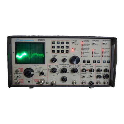
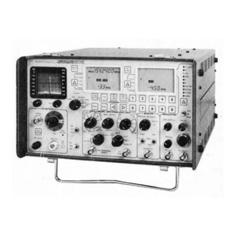
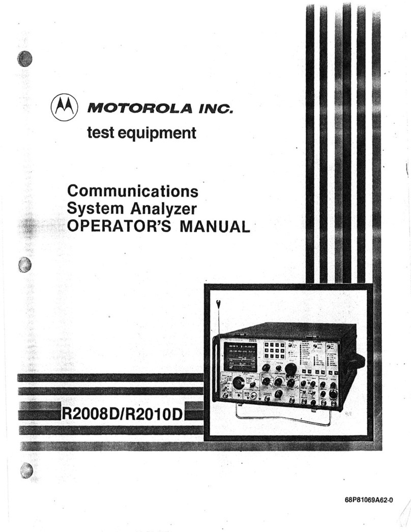
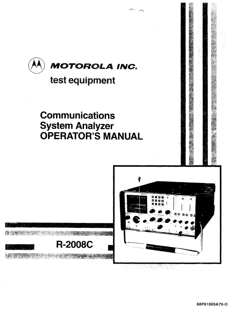
Motorola R-20018 User manual

TABLE
OF
CONTENTS
Paragraph
Page
FOREWORD
...............................................................................
1
SECTION 1
1-1
Introduction
..............................................................................
1-1
SECTION 2 - DESCRIPTION
i'
!
2-1
2-3 Description
...............................................................................
2-1
Microprocessor
...........................................................................
2-1
I 2-4
2-5
2-6
Display
..................................................................................
2-1
System Warnings
.........................................................................
2-1
Functions
................................................................................
2-1
2-7
AM,
FM,
CW,
DSB
Signal Generation
......................................................
2-2
2-8 Simultaneous Modulation
.................................................................
2-2
2-9 Modulation Display
.......................................................................
2-2
2-10 Sweep Generation
........................................................................
2-2
2-11
SINAD Metering
..........................................................................
2-2
2-12 Multi-Mode Code Synthesizer
.............................................................
2-2
2-13 Off-The-Air Monitor
......................................................................
2-2
2-14
IF
Display
................................................................................
2-2
2-15 Spectrum Analyzer
.......................................................................
2-3
2-16
RF
Burnout Protection
....................................................................
2-3
2-17 Terminated
RF
Power Measurement
.......................................................
2-3
2-18 In-Line Power Measurement
...............................................................
2-3
2-19 Duplex Generator
........................................................................
2-3
2-20 500-kHz Oscilloscope
.....................................................................
2-3
2-21
Frequency Counter
.......................................................................
2-4
2-22 AC/DC Voltmeter
.........................................................................
2-4
2-23 Power Supply
............................................................................
2-4
SECTION
3-
INSTALLATION
3-1
Packing Information
......................................................................
3-1
3-4
Initial Setup
..............................................................................
3-1
3-5 Analyzer
.................................................................................
3-1
3-6 Battery Pack
.............................................................................
3-2
3-7 Blower Assembly
.........................................................................
3-2
SECTION
4-
OPERATION
4-1
General
..................................................................................
4-1
4-3 Controls, Indicators, and Connectors
......................................................
4-1
4-5 Operation
...............................................................................
4-12
4-7 Calibrate
................................................................................
4-12

TABLE OF CONTENTS (CONT)
Paragraph Page
SECTION
4-
OPERATION (CONT)
4-8 Generator Operation
.....................................................................
4-13
4-9 Duplex Generation
......................................................................
4-14
4-10 Frequency Counter
......................................................................
4-15
4-11
Spectrum Analyzer
......................................................................
4-15
4-12 Monitor
.................................................................................
4-16
4-13 Ext Wattmeter
...........................................................................
4-17
4-14 Simultaneous Generate and Measurement Operations
.....................................
4-17
SECTION 5 - MAINTENANCE
5-1
Service
...................................................................................
5-1
5-6 Replacement Parts Ordering
..............................................................
5-1
5-9 Addresses
................................................................................
5-1
5-10 General Offices
...........................................................................
5-1
5-11
U.S.
Orders
..............................................................................
5-2
5-12 Canadian Motorola Electronics Company . .. .. . .. .. . .. . .. .. . .. .. .. . .. .. .. .. .. .. . .. . . .. .. . . 5-2
5-13 All Countries Except
U.S.
and Canada
....................................................
5-2
5-14 Major Assemblies
.........................................................................
5-4
5-16 Theory
of
Operation
......................................................................
5-7
5-17 General
..................................................................................
5-7
5-20 System
Control.
..........................................................................
5-7
5-25 Generate Mode
...........................................................................
5-7
5-34 Power Meter
............................................................................
5-13
5-40
Monitor
Mode
...........................................................................
5-14
5-52 Duplex Generator
.......................................................................
5-16
5-56 Code Synthesizer
......................................................................
··
5-17
5-65 Frequency Counter
......................................................................
5-19
5-71
Digital Voltmeter (DVM)
.................................................................
· 5-19
5-84 Oscilloscope
............................................................................
5-21
5-96 Sinad Meter
..........................................................................
·
..
5-23
5-99 Alignment Procedure
....................................................................
5-24
5-100 Introduction
.............................................................................
5-24
5-102 Test Equipment Required
................................................................
5-24
5-104 Preparation
for
Alignment.
...............................................................
5-25
5-105 Basic Alignment Procedure
..............................................................
5-25
5-118 Extended Alignment Procedure
...........................................................
5-30
5-126 Checkout Procedure
.....................................................................
5-34
5-127 Introduction
..........................................................................
···
5-34
5-129 Test Equipment Required
................................................................
5-34
5-131 Procedure
...............................................................................
5-35
5-146 System Troubleshooting
.................................................................
5-39
SECTION 6 - SYSTEM INTERCONNECT AND PARTS LISTS
ii
!
@
MOTOROLA
INC.
Communications
Group
© Motorola,
Inc:.
1980
AU
Righls
Reserved
Printed
in
U.S.A.
R-20018/R-20028
COMMUNICATIONS SYSTEM
ANALYZER
1313
E.
Algonquin Road, Schaumburg,ll. 60196 68P81069A93-0
6/30/SI·SK
j

LIST OF ILLUSTRATIONS
Figure Page TABLE OF CONTENTS
(CONT)
1-1
Communications System Analyzer
..........................................................
1-0 Paragraph Page
2-1
Accessories Supplied with Analyzer
.........................................................
2-4 SECTION
7-
LOW VOLTAGE POWER SUPPLY (A1)
3-1
Typical Communication System Analyzer Packaging
.........................................
3-1
7-1
General
..................................................................................
7-1
4-1
Controls, Indicators, and Connectors, Front Panel
...........................................
4-2 7-2 Input Power Control
......................................................................
7-1
4-2 Controls, Indicators, and Connectors, Left Side Panel
.......................................
4-3 7-6 DC Output Control
.......................................................................
7-1
4-3 Controls, Indicators. and Connectors, Rear Panel
............................................
4-3
4-4 System Analyzer Time Base Calibrate Test Setup and CRT Display
..........................
4-13
7-9 Protection
Circuitry
.......................................................................
7-1
7-13 High Voltage Supply Control
.............................................................
7-2
7-14 Switcher Module A1A1
...................................................................
7-2
4-5 Duplex Generation Test Setup and CRT Display
............................................
4-14 7-17 Output Module A1A2
......................................................................
7-2
4-6 Spectrum Test Setup and CRT Display
.....................................................
4-16
4-7 Wattmeter Test Setup and CRT Display
....................................................
4-17
7-21
Control Module A1A3
....................................................................
7-3
7-24 Relay Module A1A4
......................................................................
7-4
4-8 Test Setup for
FM
Receiver Sensitivity Using Generator and SINAD SECTION 8 - SCOPE AMPLIFIER (A2)
Meter with CRT Display
...................................................................
4-18
8-1
General
..................................................................................
8-1
4-9 Test Setup for Pager and Alert Functions with CRT Display
.................................
4-19 8-2 Deflection Amplifiers
.....................................................................
8-1
4-10 Test Setup for Using DVM and Signal Generate with CRT Display
...........................
4-20 8-3 Horizontal Timebase Generator
...........................................................
8-1
5-1
Communication System Analyzer. Top View Cover Removed
.................................
5-6
5-2 Communication System Analyzer, Bottom View Cover Removed
..............................
5-6
8-5 Horizontal Switching
......................................................................
8-1
8-6 Intensity Control
.........................................................................
8-1
8-8 Focus Control
............................................................................
8-1
5-3 Communication System Analyzer Block Diagram
..........................................
5-9 8-9 Astigmatism, Geometry, and Trace Rotation
...............................................
8-1
5-4 Generate Mode Block Diagram
............................................................
5-12
5-5 Power Meter Block Diagram
...............................................................
5-14 SECTION 9 - SCOPE/DVM CONTROL MODULE (A3)
5-6
Monitor
Mode Block Diagram
.............................................................
5-15
5-7 Duplex Generator Block Diagram
..........................................................
5-17
9-1
General
..................................................................................
9-1
9-4 Scope Vertical Control
....................................................................
9-1
9-7 SSB Detection
............................................................................
9-1
5-B
Code Synthesizer Block Diagram
..........................................................
5-18 9-8 455 kHz PLL
.............................................................................
9-2
5-9 Frequency Counter Block Diagram
........................................................
5-19 9-9 Scope Horizontal Control
.................................................................
9-2
5-10 Digital Voltmeter (DVM) Block Diagram
....................................................
5-20
5-11
Oscilloscope Block Diagram
...............................................................
5-22
9-11
Synthesizer Sweep Control.
...............................................................
9-2
9-12 Scope Z-Axis Control
.....................................................................
9-2
9-13 Modulation Display Control
...............................................................
9-2
5-12 Sinad Meter Block Diagram
...............................................................
5-24 9-17 Peak Detector
............................................................................
9-3
5-13 Scope Amplifier Alignment Points
.........................................................
5-25
5-14 Front Panel Interface Alignment Points
....................................................
5-28
5-15 Scope/DVM Control Alignment Points
.....................................................
5-29
9-18 DVM Control
.............................................................................
9-3
9-21
SINAD Detection
.........................................................................
9-4
9-22 Module Control.
..........................................................................
9-4
5-16 Horizontal Time Base Alignment Points
....................................................
5-29 SECTION
10
-RECEIVER (A4)
5-17 DVM Input Buffer Alignment Points
........................................................
5-30
10-1
General
.................................................................................
10-1
5-18 Scope/DVM Control Test Point Numbering
.................................................
5-30
5-19 Processor 1/0
A/D
Alignment Points
.......................................................
5-31
5-20 Scope/DVM Control Char Sweep and Sinad Alignment Points
...............................
5-32
10-2 Down Converter
.........................................................................
1
0-1
10-4 Linear IF
Amplifier
and Detectors
.........................................................
10-1
10-8 Audio Switching and Filtering
............................................................
10-1
10-10 Logarithmic Amplifier and Detector
.......................................................
10-2
10-11
Alarm Generator and Audio
Amplifier
.....................................................
10-2
10-12 Module Control.
.........................................................................
10-2
vi
iii

r TABLE OF CONTENTS (CONT)
TABLE OF CONTENTS (CONT) Paragraph
Page
Paragraph
Page
SECTION
16-
HIGH VOLTAGE POWER SUPPLY (A10)
SECTION
11
-
RF
SYNTHESIZER
(AS)
16-1
General
.................................................................................
16-1
16-2 High Voltage Supply
.....................................................................
16-1
11-1
General
.................................................................................
11-1
11-2 Frequency Synthesis Scheme
............................................................
11-1
SECTION
17-
RF
INPUT MODULE (A11)
11-5 310-440 MHz Phase Locked Loop
........................................................
11-1
11-6
60.5
MHz Phase Locked Loop
............................................................
11-1
11-7
550
MHz Phase Locked Loop
.............................................................
11-1
11-9 500-1000 MHz Phase Locked Loop
.......................................................
11-2
11-10 Modulation Control
......................................................................
11-2
17-1
General
.................................................................................
17-1
17-2 Input Protection and Power Meter
........................................................
17-1
17-4 Wideband Amplifier and Frequency Converter
.............................................
17-1
17-9 Duplex Generator
.......................................................................
17-2
11-11
Module Control.
.........................................................................
11-2 SECTION
18-
FRONT PANEL INTERFACE MODULE
SECTION 12 -AUDIO SYNTHESIZER (A6)
18-1
General
.................................................................................
18-1
12-1
General
.................................................................................
12-1
12-2 Private Line Generator
...................................................................
12-1
12-7 DPL Generator
..........................................................................
12-1
12-10 1 kHz Tone
..............................................................................
12-2
12-11
External Modulation
.....................................................................
12-2
12-12 Modulation Control
......................................................................
12-2
18-2 Input Coupling and Ranging
.............................................................
18-1
18-4 DVM Buffer
.............................................................................
18-1
18-5 Frequency Counter Preamp
..............................................................
18-1
18-6 Scope Vertical Preamp
...................................................................
18-1
18-7 Scope Horizontal Preamp
................................................................
18-1
18-8 Control and Display Interlace
............................................................
18-1
12-14 Module Control.
.........................................................................
12-2 SECTION
19-
10 MHz FREQUENCY STANDARD MODULE (A13)
SECTION
13-
PROCESSOR
1/0
MODULE (A7)
19-1
General
.................................................................................
19-1
13-1
General
.................................................................................
13-1
13-2 10.245 MHz Phase Locked Loop
..........................................................
13-1
13-3 System Control Bus Interface
............................................................
13-1
SECTION
20
-FRONT PANEL (A14)
20-1
General.
................................................................................
20-1
I
t .
13-6 DVM
....................................................................................
13-1
20-2 Display Board
...........................................................................
20-1
13-8 Frequency Counter
......................................................................
13-1
SECTION
21
-IEEE -488 BUS CONTROL
SECTION
14-
IEEE INTERFACE MODULE (A8)
21-1
Introduction
..........................................................................
21-1
14-1
General
.................................................................................
14-1
21-7
IEEE-488 Bus Structure
...............................................................
21-3
14.2
IEEE Bus Interface
......................................................................
14-1
21-9 Bus Signals
..........................................................................
21-3
14-3
RF
Level Control
........................................................................
14-1
21-10 Data Transfer
........................................................................
21-3
14-5 Modulation Control
......................................................................
14-1
21-12 Programming
..........................................................................
21-3
14-6 Address Decode and Control Latches
.....................................................
14-1
21-15 Command Structure
..................................................................
21-4
SECTION
15
-PROCESSOR MODULE (A9) 21-24
' 21-25 Command Strings
....................................................................
21-7
Command Types
.....................................................................
21-7
15-1
General
.................................................................................
15-1
15-2 Processor and Buffer
....................................................................
15-1
15-3 Program Memory (ROM)
................................................................
15-1
15-4 Nonvolatile Memory (NVM)
..............................................................
15-1
15-5 Random Access Memory (RAM)
.........................................................
15-1
15-6 Peripheral Interface Adapter (PIA)
.......................................................
15-1
15-7 Timing Generator
................................
·
.......................................
15-1
15-8 Character Generator
....................................................................
15-1
' . 21-29
21-30
21-35
21-36
21-42
21-45
21-46
21-53
Trigger Command
....................................................................
21-7
Return Data
..........................................................................
21-7
Programming Commands
.............................................................
21-8
Terminal Mode
.......................................................................
21-8
Error Messages
.......................................................................
21-8
Service Requests
.....................................................................
21-10
Programming Considerations
.........................................................
21-11
General
..............................................................................
21-12
21-54 R2002A Analyzer Configuration
.......................................................
21-12
SECTION
22-
BATTERY ASSEMBLY
iv
v

LIST OF TABLES
Table Page
1-1
Physical Characteristics
....................................................................
1-1
1-2 Electrical Characteristics
...................................................................
1-1
1-3
Input/Output
Characteristics
...............................................................
1-5
2-1
Accessories Supplied with the Communication Systems Analyzer
............................
2-5
2-2 Optional Equipment for Use with Analyzer
..................................................
2-5
4-1
Controls, Indicators, and Connectors
.......................................................
4-1
5-1
List
of
Subassemblies
......................................................................
5-4
5-2 Control Buses and Functions
..............................................................
5-11
5-3 Basic Test Equipment Required
...........................................................
5-24
5-4 Extended Test Equipment Required
........................................................
5-25
5-5 Test Equipment.
..........................................................................
5-34
5-6 System Troubleshooting
..................................................................
5-39
5-7 Test Point Identification
...................................................................
5-44
7-1
Control Logic Functions
..................................................................
7-3
9-1
Internal DVM Inputs
.......................................................................
9-3
21-1
IEEE-488 Interface Controllable Functions
...........................
.
..
................
22-2
21-2 Command Categories
...............................................
. .
.................
22-4
21-3 Programming Commands
...........................................
.
..
...............
22-5
21-4 Terminal Mode ASC II Characters Printable Characters
...............
.
..
..............
22-9
21-5 Error Messages
.....................................................
.
..
...............
22-10
21-6 SRQ Data
..........................................................
.
..
...............
22-10
21-7 Code Synthesizer Programming Considerations
......................
. .
................
22-11
vii

FOREWORD
1.
SCOPE OF MANUAL
This
manual
contains
information
for
t11e
installation. operation. and maintenance of the
Communications
System Analyzer.
2.
PURPOSE AND USE
The
Motorola
Communications
System Analyzer
is
a
portable
test instrument. designed specifically for the
service and
monitoring
of
communications
equipment. Its functions supersede those
of
a Service
Monitor
expanding the features and capabilities
to
the
point
wherein servicing
is
achieved with a single instrument
rather than a host
of
separate equipment.
The R2001B
is
the standard
Communications
System Analyzer. The R2002B Analyzer.
which
contains the
IEEE-488 Standard interface
control
bus, is also available.
Programming
for
the R2002B
is
covered in Seeton
21
of
this manual.
The Analyzer improves a technician's
efficiency
and
accuracy
and reduces servicing time
The
Communications
System Analyzer performs the
functions
of signal generation. signal
monitonnq
;mfl
the tests
normally
associated with the devices listed below.
• Spectrum Analyzer
•
Duplex
Generator
•
Modulation
Oscilloscope
• Frequency
Counter
•
AC/DC
Digital Voltmeter
•
RF
Wattmeter
• General Purpose
Oscilloscope
•
Multi-Mode
Code Synthesizer
•
SINAD
Meter
• Sweep
Generator
The Analyzer meets the shock and vibration requirements
of
EIA test RS1528, the same
specifications
met
by
Motorola
mobile
radios.
This
minimizes failures when the
instrument
is
used in a
mobile
service van. and
means it is as
tough
as the radios it services.
The
Communications
System Analyzer is designed to be serviced
quickly
and easily, should a breakdown
occur.
The
majority
of
the
circuitry
is on seven
modular
plug-in
circuit
boards which have
built-in
test
points
that aid in isolating the
problem
to a
specific
board.
Simple
plug-in
replacement gets the
instrument
back in
service.

CAUTION
This equipment contains parts that are subject to damage by
static electricity. Proper precautions should
be
taken during
handling.
2

ll52t-45
mama.;
mama
EIIIDI!I
l
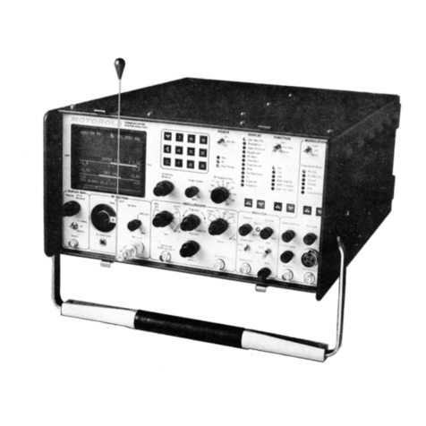
Figure 1·1. Communications System Analyzer
1-0
1
1
1
81!-\\82
1
1
1
1
1
1
1
1
1
1
1
1
1
1
1
1
1
1
1
1
1
1
1

SECTION 1
1-1.
INTRODUCTION
1-2. This section lists the physical. electrical, and
input/output
characteristics of the
Communications
System Analyzer
shown
in figure 1-1.
Table 1-1. Physical Characteristics
Characteristic Description
Length 20.75 inches (52.7 em)
Width 15.75 inches (40.0 em)
Height 8.25 inches (21.0 em)
Weight 48
pounds
(21.9 kg) (Excluding Battery Pack)
Table 1-2. Electrical Characteristics
Characteristic Description
Frequency
Range
Resolution
Accuracy
Output
(into
50
ohms)
Attenuator:
Range:
Accuracy:
Spectral
purity
Spurious:
Harmonics:
Frequency
modulation
Range:
Accuracy:
FM residual noise:
External/internal frequency
range:
External input:
Modes:
Signal Generator Mode
10 kHz to 999.9999 MHz
100Hz
Equal to master
oscillator
time base
16
dB
variable plus 10 dB steps over
13
ranges
0.1/1 V
to
1 Vrms (-127
dBm
to +13
dBm)
±2
dB
accuracy on 0 dB step attenuator range
±2
dB
across
other
step
attenuator
ranges
±1
dB
over temperature range
~-40
dB
~-15
dB
0 - 50 kHz peak
±5%
of
full scale
100Hz
5Hz-
10kHz
(±1
dB)
Approximately
150 mV for
20
kHz deviation
Internal. external,
microphone
or
all simultaneously

Table 1-2. Electrical Characteristics (Continued)
Characteristic I Description
Manual Frequency Scan
Step size Switch Selectable: 100 Hz, 1 kHz,
10
kHz. 100 kHz and
1 MHz
(+
or-)
Step rate 5 steps/sec.
Time
Base
Standard TCXO Aging: ±1 x 10-" per year
Temp:±
1 x 10-s
maximum
error
over the
oo
to
55°C
temp. range
Optional
ovenized
high
Agir.;r
±1 x 1
o-'
per year
stability
Temp:
±5
x
10-
6 maximum
error
over the
oo
to
55° C
temp range (warmup to
±5
x 1
o-'
of
final frequency
within
20 minutes)
Power
and Environmental
-
AC
100-130 VAG, 200-260 VAG
47-63Hz
DC +11.5 VDC to +16 VDC
Optional
battery 13.6V battery -provides 1
hour
continuous
operation
Temperature range
0'
to 55°C operating;
-40
to
85'
C storage
-
Table 1-3.
Input/Output
Characteristics
Characteristic
Ext mod in
Mic.
Ext Horiz
Vert/Sinad/DVM/Counter
In
Description
Input
10K ohms nominal, 150 mV typical for
20kHz
dev. FM
or
80%AM
Mic
input
provides bias and
IDC
limiting suitable for
Motorola
RTM 9000A handseL PTTswitches
R2001
from
monitor
to
generate.
1volt
minimum
for full screen deflection.
Maximum
input
10 volts.
1 Meg ohm, 40 pf Nominal; ±300volts DC max, 300 Vrms
max at frequencies
below
500 Hz,
10
Vrms max up to
35 MHz
• Scope vert in: DC
to
500 kHz
or
5o
Hz
to
500kHz
AC
mode (±3
dB)
• Sinad in: 0.5 to 10 Vrms in at 1 kHz
1-5
·--
Table 1-2. Electrical Characteristics (Continued)
Characteristic Description
l------------------------------1-------------------
--------
Amplitude
modulation
Range:
Accuracy:
External/internal frequency
range:
External input:
Modes:
Double
sideband suppressed
carrier
0 to
80%
from 1 to 500 MHz
± 10% of full scale from
0%
to
50%
AM
5Hz-10kHz
(±1
dB)
Approximately
150 mV for 80%,
BNC
connector
Internal, external,
microphone
or
all simultaneously
Carrier suppression:
?io
25
dB
(1
MHz-
500 MHz)
~------~~----------~-------
Frequency
Range:
Resolution:
Accuracy:
Frequency
error
indicator
Input
sensitivity
Spurious
response
Deviation Measurement
Range:
Accuracy:
Peak deviation
limit
alarm:
AM
modulation
measurement
Range:
Accuracy:
Monitor
Mode
1 MHz to 999.9999
MHz
100Hz
Equal to that of master oscillator
lime
base
Autoranging
CRT display. ±
10
Hz resolution for
frequency
error
measurements on 1.5 kHz,
5kHz
and
15
kHz full scale ranges.
±1
Hz resolution on the 50 Hz
full scale range.
1.5/1
V for 10
dB
EIA Sinad (narrow band
±6
kHz
mod. acceptance) 7
Jl.
V for
10
dB EIA Sinad (wide
band±
100 kHz mod. acceptance) 4 MHZ to 1000 MHz.
Useable to 1 MHz.
-40
dB typical
0 dB image at ±21.4 MHz
-10
dB
at L.O.
harmonics
±10.7
MHz
1,
10,
100 kHz full scale
±5%
of
reading
±100Hz
from
500Hz
to
50
kHz deviation;
±10%
of
reading from 50 kHz to
75kHz
deviation
Set via keyboard
to
100Hz
resolution
(0
kHz to
99.9 kHz).
Audible
alarm indicates
limit
condition
in all
Monitor
Modes.
0 to 100%
±5% of full scale
1-2

Table 1-3.
Input/Output
Characteristics (Con!)
Characteristics
RF
In/Out
Ext Wattmeter
10
MHz std in (rear panel)
Mod
out
Demod
out
RF
in/out
Duplex gen
out
10
MHz
std
out
(rear panel)
Description
• DVM in:
1.
10,
100 and 300V full scale AC
or
DC. AC
bandwidth
50
Hz to
10kHz
for ±5%
F.S.
accuracy (AC
dBm
calibrated across 600 ohms)
• Frequency
counter
in: 30 mV
or
greater required from
10Hz
to 1 MHz.
50
mV
or
greater required from 1MHz
to 35
MHz
50 ohms nominal, 125 watts max (1-1000 MHz)
CAUTION:
The
RF
In/Out
Jack
is protected against
RF
overload. However.
to prevent
undue
stress on the protected
circuits
it
is
advisable
to always
switch
the system to the power
monitor
mode before
applying
power
in excess of 200 mW. Additional protection
is
also obtained
by
making it a practice not to leave the step
attenuator in the 0 dB position.
Characteristics suitable for Motorola ST-1200 series
Wattmeter Elements
70
to
350 mV rms
input
required at 10 MHz,
impedance greater than
50
ohms.
Output
Up to
11
vpp
into
600 ohms 10 Hz to
10
kHz
Typically
3
vpp
into
600 ohms for
±5
kHz deviation
narrowband, 4
vpp
for±
75
kHz deviation wideband.
DC
to
10kHz
response
1.0 Vrms (+13
dBm)
to
0.1
Vrms (-127 dBm)
50
ohm
nominal source impedance.
10kHz
to 1.0 GHz.
-30
dBm
typical, 50 ohm nominal source impedance
2 MHZ to 1 GHz
250 mV rms nominal
output
into
50
ohms
1-6

Table 1-2. Electrical Characteristics (Continued) Table 1-2. Electrical Characteristics (Continued)
Characteristic Description Characteristic Description
Digital Voltmeter
RF
Wattmeter
(Autoranging display) Readout
Auto
ranging digital display,
1,
10,
100,
300 volts full
Frequency range: 1 MHz to 1000 MHz scale. AC-dBm calibrated across
600
ohms.
Power range: 1.0 watts to 125 wattts DC accuracy ±
1%
of
full
scale±
1 least significant digit
Accuracy: ±
10%,
1 watt to 125 watts AC accuracy ±5%
of
full scale
Protection Over temp indicator AC bandwidth 50 Hz to
10kHz
General Modulation Source
Spectrum Analyzer Code Synthesizer
Dynamic range
"?-75
dB
displayed,-
105 dBm to +30 dBm
input
range Frequency range 5 Hz to g,9999 kHz sinewave
with step attenuator Resolution
0.1
Hz
Frequency Frequency accuracy ±0.01%
Range 4 MHZ to 1,000
MHZ
Distortion
~1%
Full scale frequency Adjustable between 1 MHz and
10
MHz Signaling sequences Four fixed
dtspersion:
1.
Tone
only
2.
Tone with battery saver
Duplex Generator
3.
Tone and voice
4.
Group
call
Frequency offset Adjustable from 0 to
10
MHz plus fixed offset of Four user programmable
45
MHz (high or
low
side) Tone remote access Remote base access sequence
as
follows
Modulation level (FM
only)
Adjustable from 0 to 20 kHz peak deviation Tone A
for
150 msec
Tone B for
40
msec
10
dB below Tone A
Oscilloscope Tone A continuously 30 dB below the first Tone A
burst
Size 8
em
x
10
em Digital private line (DPL) Codes 000 to 777 and inverted
Frequency response DC to 0.5 MHz (3 dB point) Fixed 1 kHz
External vertical
input
range 10 mV, 100 mV, 1V, 10V (per division) Accuracy Equal to master time base
Sweep rates 1
Jl
s,
10
Jl
s,
0.1
ms, 1 ms, 0.01S, 0.1S (per division) Distortion
::;:;1%
Sync Automatic
or
normal triggering External Input
Microphone Standard RTM 4000A microphone interface with !DC.
Frequency Counter External Jack
Frequency range 5 Hz to
10
kHz
Frequency range Level 7 vrms maximum
10Hz
to
35
MHz Impedance
10
Kohm nominal
Readout 5 digit, autoranging Code synthesizer external 0-3 vrms into a 600 ohm load
Input sensitivity 30 mV from
10
Hz
to 1 MHz
output
level
50
mV
from 1 MHz to
35
MHz
SlNAD
Meter
Input level range 0.5V to
10
Vrms
Sinad accuracy ±1 dB at
12
dB Sinad
1-3 1-4

2-7. AM, FM, CW, DSB Signal Generation. The
built-in
general purpose signal generator provides
continuous
coverage of the HF, VHF, and UHF land mobile spectrum for receiver testing. Many forms of
external and internal modulation can be simultaneously impressed on the carriersignal
for
actual composite
signals. The frequency range
of
the
RF
signal generator
is
from
10kHz
to
1000MHz in
100Hz
steps.
Tt1e
output
of
up to 1 Volt rms provides sufficient amplitude to get through misaligned tuners and receivers. and
is
especially effective when changing a receiver's frequency. The high level, clean
output
is available over the
entire frequency range
of
the
Communications
System Analyzer. The
output
frequency is referenced to
an
internal time base
which
can be calibrated
to
the WWV Standard. (See paragraph 4-7.)
2-8. Simultaneous Modulation. Modulation is simultaneously available from an internal 1 kHz tone
generator, a
multi-mode
code synthesizer, and from external inputs. The external modulation can be voice
from a standard
Motorola
mobile
radio
microphone
(which plugs
into
the front panel ofthe instrument).
as
well
as
a signal applied
to
the external BNC input. Separate controls are provided for independently setting the
levels
of
the 1 kHz tone, the code synthesizer, and the external modulation sources. The 1 kHz test tone is a
convenient source
of
modulation
for
making SINAD measurements. A MOD
OUT
connector
providesexternal
access to all
of
the
modulation
signals.
2-9.
Modulation
Display. The recovered audio waveform,
or
audio used
to
modulate the generator carrier,
can be viewed on the CRT. It is used to graphically measure deviation, and to aid in waveform analysis.
2-10. Sweep Generation. The sweep generator mode provides
an
RF
output
that is swept in frequency
across a band centered at the programmed frequency. A synchronized horizontal sweep
for
the internal
oscilloscope allows filter characteristics to be easily determined. This is ideal for in-depth troubleshooting of
IF amplifiers and filters.
2-11. SINAD Metering. A comprehensive check of receiver performance can be made with a SINAD
measurement. The analog line segment and digital representation
of
SINAD appear automatically whenever
the
unit
is in the normal generate mode. The
only
hookups
required are from the
Communications
System
Analyzer
to
the
RF
input
of
thereceiver
under
test, and from the audio
output
ofthe receiver to theinstrument's
multipurpose
input. The measurement, and appropriateservicing, can then be accomplished
without
the need
for
a separate signal generator,
SINAD
meter
or
distortion
analyzer.
2-12.
Multi-Mode
Code Synthesizer. The
Communications
System Analyzer generates Private Line tones
(PL), Digital Private Line codes (DPL),
two-tone
sequential paging codes and tone-remote base signaling
tones. All codes are available at the Mod
Out
jack,
as
well
as
being used internally to modulate the
RF
signal
generator. This eliminates the necessity
of
using separate generators and oscillators
for
general servicing,
setting transmitter deviation,
or
for
checking tone-remote-base
control
lines.
Timing
sequences are also
stored in the
Tone
Memory
to
provide fast set-up and eliminate errors. Userprogrammable timing sequences
are also provided to
allow
the storage
of
non-standard
or
future time sequences.
2-13. 011-lhe-Air
Monitor.
The 1.5
11
V sensitivity
of
the Communications System Analyzer receiver allows
off-the-air
monitoring
and measurement
of
transmitter frequency error and deviation
to
1000 MHz. A variable
squelch allows weak signals to be monitored, but can be set higher
to
ensure the
proper
signal-to-noise ratio
for
measurement accuracy. The off-the-air
monitor
function enables frequent parameter checks
without
leaving the shop, thus spotting system degradation early and keeping service costs down.
Bandwidth
can
be
set Wide
for
off-channel signal location
or
wide band FM;
or
Narrow
for
maximum sensitivity and selectivity.
2-14. IF Display. When the IF display mode is selected, the Communications System Analyzer's receiver
IF
envelope is shown on the CRT. This allows the technician to qualitatively and quantitatively assess the
amplitude modulation envelope
of
a transmitter.
2-2
2-15. Spectrum Analyzer. In this mode
of
operation the CRT displays a
window
of the
RF
spectrum whose
bandwidth (from 1MHz
to
10 MHz) is determined by the DISPERSION/SWEEP control. The centerfrequency
of
this
window
ranges from 4 MHz to 1,000 MHz. selectable by entering a specific center frequency with the
keyboard. This center frequency
is
digitally
displayed
at
the top
of
theCRT screen,eliminating the need
for
an
external signal generator. and
counter
to
provide markers. Once a signal is centered on the screen, positive
identification
is
aided by switching the Analyzer
lo
MONITOR AM
or
FM
and listening to the demodulated
output
via the built-in audio amplifier and speaker. Thespectrum analyzer's center frequency can be scanned
up
or
down
at
rates varying from 0.5 kHzpersecond to 5 MHzper second, usingthe
RF
scan control.Slowrates
are used
to
precisely determineasubjectsignal's frequencywhilefaster rates are used
for
locating intermittent
transmissions
or
viewing large areas
of
the spectrum in a short time. Uses of the Spectrum Analyzer
are:
lntermodulation
interference identification,
IF
and
RF
signal tracing, transmitter harmonics
measurements, transmitter spurious checks, and receiver local oscillator radiation.
2-16.
RF
Burnout
Protection. At
RF
input
levels above 200 mW, in any operating mode, the
input
automatically switches to the
internal125
watt
RF
load, thus
protecting
the attenuator and signal generator
against damage from a keyed transmitter. If
power
above 200 mW is applied in any mode except the power
monitor
mode an audiable alarm sounds and a visual warning on the CRT directs the operator to switch to the
power
monitor
mode.
CAUTION
To
prevent undue stress on the protected
circuits
it is advisable to always switch the
system to the power
monitor
mode before applying power in excess
of
200 mW.
Additional protection is also obtained by making it a practice not to leave the step
attenuator in the 0
dB
position.
2-17. Terminated
RF
PowerMeasurement.
RF
poweris automaticallymeasured when the Communications
System Analyzer is in the
Power-Monitor
mode. The
built-in
RF
load dissipates up
to
50
watts
for
threeminutes
and
up
to
125
watts
lor
one minute.
If
a high
power
transmitter should be keyed
into
the unit
for
a time long
enough to threaten overheating
of
the power measuring circuitry, the audible alarm sounds and the CRT
display changes to read "RF
LOAD
OVER-TEMP," thus warning the technician to un-key. This instrument
function is further enhanced by the simultaneous indication
of
RF
power
output, carrier frequency error. and
modulation, all on the same CRT display.
2-18. In-Line Power Measurement. Use
of
the Motorola ST-1200 series Wattmeter elements in
conjunction
with the analyzer's external wattmeter display provides measurement of forward and reflected antenna
power
on the CRT display. This capability eliminates the complex hook-ups and theadditional instruments normally
required for antenna measurements.
2-19. Duplex Generator. In this mode, the Communications System Analyzer simultaneously receives and
generates the signals
for
duplex radio servicing, while generated and monitored frequencies are observed on
the CRT. In the 0-10 MHz range, the 'Freq. Set' control tunes the proper offset frequency for theVHF and UHF
bands. The
45
MHz mode providesasingleoffset
for
the 800 MHz range. Aswitch is also provided to select high
or
low side offset.
as
required. The Duplex Generatorprovides enhanced capabilityto service equipmentsuch
as
repeaters, car telephones and Emergency Medical Telemetry portables.
2-20. 500-kHz Oscilloscope. This general purpose scope is ideal for waveform analysis in two-way
communication servicing. Use
it
for viewing modulation signals (either internally
or
externally generated),
detection of asymmetric modulation
or
audio distortion, and general purpose signal tracing and
troubleshooting.
2-3

2-21. Frequency
Counter.
The
frequency
counter
measures
inputs
in a range
from
10Hz
to 35 MHz. Its 5
digit
auto-ranging
output
is displayed
on
the
CRT
and allows precise measurement and setting
of
offset
oscillators,
35kHz
and
455kHz
pager IF's, PL frequencies and
other
external
input
signals.
This
function
will
also
operate
simultaneously
with the generate
or
monitor
receiver modes
of
operation. Frequency
measurement
of
transmitted carriers and
other
signals
higher
than 35 MHz is easily
accomplished
with
the
frequency
error
readout in the
monitor
modes.
2-22.
AC/DC
Voltmeter.
Switching
to the DVM
mode
provides a
digital-analog
voltage presentation
on
the
CRT, along
with
the
corresponding
dBm
value.
The
auto-ranging
display provides full scale
deflections
of
1.
1
o.
100 and 300 Volts. AC
or
DC
measurement is selected
on
the CRT.
The
meter's
wide
dynamic
range and
three
digit
display
are ideal
for
setting
power
supply
voltages. checking bias levels, and setting
audio
levels.
Like the
Frequency
Counter,
the DVM will operate
simultaneously
with
generate
or
monitor
operation.
2-23.
Power
Supply.
The
Communications
System Analyzer may be powered
by
a variety
of
sources:
•
•
•
AC at 110
or
220 Volts, 50/60 Hz
DC
from an external 12
Volt
source
such
as a service vehicle
DC
from an
optional
battery
pack. Servicing can
t11us
be accomplished wherever the
equipment
under
test is located
2-24. ACCESSORIES.
2-25. Table
2-1
lists theaccessories supplied with the
Communication
System Analyzer.
Optional
equipment
available
for
use
with
the
unit
is listed in
Table
2-2.
ACCESSORY
KIT
··:;:
.
PERfORMANCE
RENlRT
'
Figure 2-1. Accessories
Supplied
with Analyzer
2-4
2-1. DESCRIPTION
SECTION 2
DESCRIPTION
2-2. The
Communication
System Analyzer
is
a
portable
test
instrument
designed
for
servicing and
monitoring
of
portable,
mobile,
and land base
communications
equipment
operating over the frequency range
of
1 MHz to 1 GHz.
The
unit
performs
the
functions
of signal generation.
frequency
error
and
modulation
measurement. It
is
also capable
of
a variety
of
tests
normally
associated with the
following
devices:
Spectrum
analyzer
Duplex
offset
generator
Modulation
oscilloscope
Frequency
counter
AC/DC
digital-analog
voltmeter
RF
wattmeter
General purpose
oscilloscope
Multi-mode
code synthesizer
SINAD
meter
Sweep
generator
2-3. MICROPROCESSOR. A
Motorola
M-6800 series
microprocessor
permits keyboard
entry
of
data,
autoranging
of
displays, fast
frequency
access. and permanent storage
of
often-used frequencies and codes.
Generate and
monitor
RF
frequencies, tone codes. and
timing
sequences can be
programmed
into
a
nonvolatile
memory, saving time and
eliminating
entry
errors. When one
particular
type
of
equipment
is
continuously
serviced. the
unit
can be
programmed
to select the
mode
of
operation
required when first turned
on.
2.4 DISPLAY. All functions, generated
or
monitored,
are presented
on
an
8 em x 10
em
cathode
ray tube
(CRT) in both analog and
digital
format,
with
the name
of
the
function
being displayed. The CRT also displays
control
settings
eliminating
the need
for
operator
search
of
different
equipment
panels. Digital readouts are
visually aided by the use
of
the
continuously
autoranging
analog line segments, wl1ich are
similar
to a
ba1
graph. Each has a base
line
and
calibration
markers, in
addition
to the intensified segment
showing
the
measurement.
The
user selectable displays are listed in a
column
beneath the DISPLAY heading on the front
panel.
Choosing
a display is
accomplished
by
pressing an arrow
button
below the
column,
for
up
or
down
movement,
as
required. When the
appropriate
arrow
is pressed. the LED adjacent to the selected display
illuminates.
FUNCTION
is selected in the same way,
providing
rapid, accurate changes in service
capability
at
the touch
of
a
button.
2-5. SYSTEM WARNINGS.
To
aid the
technician
in servicing, visual
warnings
will appearon the CRT when
certain overload
or
caution
conditions
exist. Displayswarn
of
low
battery power, overheating
of
the
RF
load,
or
an
improper
attenuator
setting
for
particular
measurements. In addition, a
continuous
audible
alarm sounds
when a preset deviation
limit
is exceeded in
monitor
modes.
This
limit
is entered by using the keyboarcl and
may be
programmed
from 0 kHz to 99.9 kHz,
with
100 Hz resolution.
2-6.
FUNCTIONS.
The
following
paragraphs briefly
describe
the
major
functions
of the
Communications
System Analyzer.
2-1

L
n
IF
JUc
"
ati
to
iar
:im
rtn
"'
orr
'"
es
inr
fil
Table 2-1. Accessories Supplied with the Communication Systems Analyzer
Equipment Motorola Part No. Use
Front
cover 15-80335A70 Front panel and CRT protection, storage of cables,
power
cord, and other equipment for on-site
servicing.
Sun shade 15-80335A55 Snap over CRT during use in
bright
sunlight.
Power
cord
30-80336A36 Three
conductor
cord to supply
AC
power
to unit.
Also used when charging optional battery pack.
Oscilloscope probe RTL-4058A A
X1
probe with attachments for general servicing.
In-line wattmeter adapter RTL-4055A Allows use
of
Motorola ST-1200 series in-line watt-
meter elements for direct measurement and display
of forward and reflected transmitted power.
Coax adapter 58-84300A98 Adapts front panel
"N"
connector
to BNC female
Antenna TEKA-24A Plugs
into
RF
in/out
connector on front panel with
N to BNC adapter. Used
for
off-the-air
transmitter
and receiver tests.
Test microphone RTM-4000A Used for voice modulation of signals.
Connector
kit RPX-4097A Consists of
connector
shell, clamp, and four
connector
pins. Used to fabricate a mating plug for
male de power
connector
at back
of
analyzer.
Enables user to make a de power cable
to
inter-
connect separate power source
to
analyzer. Pins 1
and 2 are positive, pin 3
is
the charging line, pin 4 is
ground.
Table 2-2. Optional Equipment for Use with Analyzer
Equipment
Motorola
Part No. Use
IEEE-488 Standard Consult factory Enables fully automatic testing
with
the
unit
im
~rface
bus option for retrofit
by
external control from a
computer
or
information. programmable controller.
2-5

Table 2-2. Optional Equipment for Use
with
Analyzer (Con!)
Equipment
Battery
pack
High-stability
oscillator
module
Protective cover
Motorola Part No.
RTP-1002A
RTL-1007A
RTL-4056A
Use I
13.6 volt battery and charger attaches to back
of
the unit. Provides one
hour
of
continuousoperation. I
Cannot
be used with IEEE-488
or
Blower options.
Improves
stability
of the time base
as
specified in
electrical characteristics section.
Padded fabric type cover to protect unit from
excessive field wear.
2-6

3-1. PACKING INFORMATION
SECTION 3
INSTALLATION
3-2_-
The
unit
ispackaged inafiberboard carton and protected
by
foam pieces
as
shown in figure3-1. The
unit
IS first packed in a cardboard containerand then this carton is packed in asecond, largercardboardcontainer,
for further protection. Save the packing container and materials for future use.
Figure 3-1.
Typical
Communication
System Analyzer Packaging
3-3. All accessories supplied with the analyzer are packed in the analyzer cover.
3-4. INITIAL SETUP
3-5. ANALYZER.
To
set up the Analyzer for use, place the unit on workbench
or
in
mobile
repair
unit
Remove the front cover by operating the
two
latcheson thebottom of thecover. Lift thecoverand slide
it
to the
side to separate the hinges. Remove the power cord (AC
or
DC) that is stored in the cover. Attach the female
connector
of
the power
cord
to
the appropriate
connector
on the rear panel
of
the analyzer, and the
other
end
to the
power
source. For AC power a
grounded
3 wire power source of 100-130 Vac
or
200-260Vac,
47-63Hz
must be used.
3-1

NOTE
The
unit
is set for 110-130 Vac operation from the factory. For operation from 100-
110 Vac
or
200-260 Vac, the voltage selection card must be readjusted before
connection
to
the power source. This is accomplished
by
the following procedure:
1.
Remove the
power
cord
from the rear panel connector.
2.
Slide the selector card cover
door
over the
connector
area exposingthe selection card and
fuse area.
3.
Pull outward on the fuse ejector tab and remove fuse.
4.
Remove the printed
circuit
board voltage selector card by
pulling
straight
to
the rear.
5.
Reinsert the card
at
the orientation
which
causes the appropriate voltage range (marked
on card) to
be
displayed.
6.
Reinstall the fuse.
7.
Slide the cover plate back to the original position, connect power cord, and proceed with
system operation.
Remove the accessories to be used from the cover. Move the POWER switch to the ON position. When the
Oven Ready
indicator
illuminates the unit's frequency standard is stabilized and the
unit
is ready
for
use,
(instantaneous with standard TCXO).
CAUTION
When installing the analyzer in avehicle, theDC
supply
lineshould be fused close
to
the vehicle battery. The analyzer is protected against overload bythe
DC
SA
fuse on
the rear
of
the unit,
but
the vehicle is
not
protected.
3-6. BATTERY PACK.
The
battery pack isattached to the rear
of
theanalyzerwith twoclips and
two
screws.
Align and slide the mounting clips
of
the batterypack
into
theslots on the
mounting
bracketson the leftside
of
the back panel
of
the analyzer. Align the captive screws with the
mounting
holes on the right
of
the panel and
lighten. Connect the power
plug
to the
connector
at the top right
of
the rear panel.
3-2

Item
RF
Scan (Hz/Sec)
switch
POWER switch
Batt
indicator
AC
indicator
Oven Ready
indicator
DISPLAY
indicators
Table 4-1. Controls, Indicators, and Connectors
(Coni)
Description
Eleven
position
switch
Three-position
toggle
switch.
LED (red) I
LED (red)
LED (red)
Twelve LEOs (red)
Function
Allows
automatic
scan of the generated
or
the
monitored
frequency. The switch setting indicates
rate
of
frequency change.
The
rate is 5 steps per
second, with frequency steps of 100 Hz,
1 kHz,
10kHz,
100kHz
and 1 MHz.
a.
Energizes all
circuitry
in the On position.
b.
At Standby position, removes DC from all
circuitry
except the frequency standard and
battery charger.
c.
At Off,
only
the battery charging
circuitry
is
operative if
an
ac
power
source
is
being
used.
Illuminates when
equipment
is using DC power.
Illuminates when
equipment
is connected
to
an
ac
power
source. Position of POWER switch has no
effect on indicator. Equipment
automatically
switches to ac
power
source when connected
to
ac line voltage.
Illuminates when optional frequency standard
oven has stabilized.
Continuously
illuminated
with
the TCXO frequency standard.
Illuminate one at a time to indicate the
function
or
type
of
operation the equipment is
performing
and the
information
displayed on the CRT.
a.
b.
c.
4-4
Gen/Mon
Mtr-
In the generate
mode
the
center frequency,
output
power, and
modula-
lion
depth
of
the
RF
output
is displayed. In
the
monitor
mode
the center frequency,
input
power, frequency error, and
modula-
lion
depth
of the received carrier is
displayed.
Modulation
-The
modulation
audio
in the
generate mode
or
the demodulated audio in
the
monitor
mode is displayed.
Spect Analyzer -The spectrum analyzer
mode
is enabled. The
RF
spectrum and the
operating center frequency
is
displayed.
l
I
4-1. GENERAL
SECTION 4
OPERATION
4-2.
This
section contains
information
for
the operation
of
the
Communication
System Analyzer.
4-3. CONTROLS, INDICATORS, AND CONNECTORS
4-4.
The
analyzer controls, indicators, and
connectors
are
shown
in Figures
4-1
through 4-3 and listed
with
their
functions
in Table 4-1.
Table 4-1. Controls, Indicators, and Connectors
c--------..--------..------_,
______________
,
..
____
_
Item Description Function
1--------...L
_________
J._
___________________
_
Keyboard
<l
0
through
9
• Intensity
• Focus
Dispr/Sweep
control
FRONT PANEL (fig. 4-1)
Twelve-key
pushbutton
keyboard
Line
cursor
key
Horizontal
cursor
key
Numerical
keys
Stacked
concentric
potentiometers
• Intensity -center
(small)
knob
• Focus -outside
(large)
knob
Potentiometer
4-1
Enters variables
into
memory/enters manual
variables/selects variables to be used from the
memory.
Moves the cursor
down
to the next line that may
be changed. Preset permanent entries are skipped.
Cursor
will move
down
only. When
on
last line,
will return
to
top
line with next entry.
Moves the horizontal
cursor
left to the next entry
position that may be changed. When in the last
left position, the
cursor
will move
to
the far
right
with the next entry.
Used
to
select from the memory a stored value
to
be
used,
or
to enter
directly
a value to be used.
Controls
the intensity
of
the scope presentation.
Controls
the focus of the scope presentation.
Controls
the frequency span (1-10 MHz) displayed
on the CRT when unit is used
as
a spectrum
analyzer. Provides sweep width
control
when
either sweep
function
(SWP 0.01-1
MHz
or
SWP
1-10 MHz) is selected.

••••••
••••••
Oi
c
"'
c..
c:
0
~
u.
ui
~
0
ti
"'
c
c
0
(.)
"0
c
"'
ui
~
0
"'
.2
"0
c
ui
"6
~
c:
0
(.)
~
'
""
())
~
"
en
u::
4-2
I
0
"'
sus
Figure 4-2. Controls, Indicators, and Connectors, Left Side Panel
AC
lOA
®·,----------,@
Figure 4-3. Controls, Indicators, and Connectors, Rear Panel
4215-18
4-3
This manual suits for next models
1
Table of contents
Other Motorola Measuring Instrument manuals

Motorola
Motorola S1051C User manual

Motorola
Motorola R2008C User manual

Motorola
Motorola R-2550 Owner's manual

Motorola
Motorola R-20010 User manual

Motorola
Motorola R-2002A User manual

Motorola
Motorola R2010D User manual

Motorola
Motorola R-2001A User manual

Motorola
Motorola R-2200 User manual

Motorola
Motorola R-2001D User manual

Motorola
Motorola SCOUT2300/2 User manual