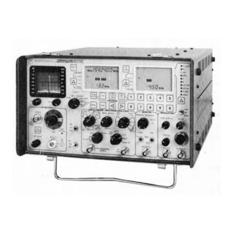
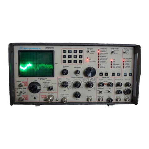
Motorola R-2001A User manual

MOTOROLA
INC.
Communications
Group
R-2001A/R-2002A
COMMUNICATIONS SYSTEM
ANALYZER
© Motorola, Inc. 1980
All Rights Reserved
Printed in U.S.A. 1313 E.Algonquin Road, Schaumburg, II. 60196 68P81069A84-0
5/
30
/80-SK

TABLE OF CONTENTS
Paragraph Page
FOREWORD
................................................................................
SECTION 1
1-1Introduction .............................................................................1-1
SECTION 2 — DESCRIPTION
2-1Description ..............................................................................2-1
2-3 Microprocessor ..........................................................................2-1
2-4 Display
..................................................................................
2-1
2-5System Warnings
.........................................................................
2-1
2-6 Functions
................................................................................
2-1
2-7AM, FM,CW, DSB Signal Generation
......................................................
2-2
2-8 Simultaneous Modulation
.................................................................
2-2
2-9Modulation Display
.......................................................................
2-2
2-10 Sweep Generation
........................................................................
2-2
2-11 SINAD Metering ..........................................................................
2-2
2-12 Multi-Mode Code Synthesizer
.............................................................
2-2
2-13Off-The-AirMonitor
......................................................................
2-2
2-14 IFDisplay
................................................................................
2-2
2-15Spectrum Analyzer
.......................................................................
2-3
2-16
RF
Burnout Protection
....................................................................
2-3
2-17Terminated
RF
Power
Measurement
.......................................................
2-3
2-18
In-Line Power Measurement .....................................................................
2-3
2-19 Duplex Generator
........................................................................
2-3
2-20 500-kHz Oscilloscope ............................................................................2-3
2-21 Frequency Counter
.......................................................................
2-4
2-22
AC/DC Voltmeter.........................................................................
2-4
2-23 Power Supply
............................................................................
2-4
2-24 Accessories
..............................................................................
2-4
SECTION 3 — INSTALLATION
3-1
Packing Information
......................................................................
3-1
3-4
Initial
Setup
..............................................................................
3-1
3-5
Analyzer
.................................................................................
3-1
3-6
Battery
Pack
.............................................................................
3-2
3-7Blower Assembly
.........................................................................
3-2
SECTION 4 — OPERATION
4-1 General .................................................................................4-1
4-3 Controls, Indicators, and Connectors
......................................................
4-1
4-5 Operation
................................................................................
4-12
4-7 Calibrate
...................................................................................
4-12
i

TABLE OF CONTENTS (CONT)
Paragraph Page
SECTION 4 — OPERATION (CONT)
4-8 Generator Operation ..............................................................................4-13
4-9 Duplex Generation
..........................................................................
4-14
4-10 Frequency Counter
...........................................................................
4-15
4-11
Spectrum Analyzer
.......................................................................
4-15
4-12
Monitor
..................................................................................
4-16
4-13
Ext
Wattmeter
...........................................................................
4-17
4-14 Simultaneous Generate and Measurement Operations
.....................................
4-17
SECTION 5 — MAINTENANCE
5-1 Service .................................................................................................5-1
5-6 Replacement
Parts
Ordering
........................................................................
5-1
5-9 Addresses .................................................................................................5-1
5-10 General Offices ......................................................................................5-1
5-11 U.S.Orders.
.............................................................................5-2
5-12 Canadian Motorola Electronics Company
.......................................................
5-2
5-13 AllCountries Except U.
S.
and Canada
....................................................
5-2
5-14 Major Assemblies .............................................................................5-4
5-16 Theory of Operation
......................................................................
5-5
5-17 General
..................................................................................
5-5
5-20 System Control ...............................................................................5-5
5-25 Generate
Mode ..........................................................................
5-5
5-34 Power Meter
...............................................................................
5-11
5-40 Monitor Mode
............................................................................
...5-12
5-52 Duplex Generator
........................................................................
5-14
5-56 Code Synthesizer ..............................................................................5-15
5-65 Frequency Counter
........................................................................
5-17
5-71 Digital Voltmeter (DVM) .........................................................................5-17
5-84 Oscilloscope
............................................................................
5-19
5-96 Sinad Meter
.............................................................................
5-21
5-99
Alignment
Procedure
....................................................................
5-22
5-100
Introduction ............................................................................
5-22
5-102Test Equipment Required
................................................................
5-22
5-104 Preparation for
Alignment ...............................................................
5-23
5-105BasicAlignment Procedure
..............................................................
5-23
5-118Extended Alignment
Procedure ..........................................................
5-27
5-126 Checkout
Procedure ....................................................................
5-32
5-127
Introduction ............................................................................
5-32
5-129Test Equipment Required
................................................................
5-32
5-131
Procedure ..............................................................................
5-33
5-146System
Troubleshooting
.................................................................
5-37
SECTION 6 — SYSTEM INTERCONNECT AND PARTS LISTS
ii

TABLE OF CONTENTS (CONT)
ParagraphPage
SECTION 7 - LOW VOLTAGE POWER SUPPLY (A1)
7-1General
..................................................................................
7-1
7-2 Input Power
Control
......................................................................
7-1
7-6 DC Output Control
........................................................................7-1
7-9 ProtectionCircuitry .........................................................................7-1
7-13High VoltageSupply Control
..............................................................
7-2
SECTION 8 — SCOPE AMPLIFIER (A2)
8-1
General
..................................................................................
8-1
8-2 DeflectionAmplifiers
.....................................................................
8-1
8-3Horizontal Timebase Generator
...........................................................
8-1
8-5 Horizontal Switching ..................................................................... 8-1
8-6
Intensity
Control
......................................................................
8-1
8-8Focus Control
............................................................................
8-1
8-9 Astigmatism,Geometry, and TraceRotation
...............................................
8-1
SECTION 9 - SCOPE/DVM CONTROL MODULE (A3)
9-1 General
.................................................................................
9-1
9-4Scope Vertical
Control ..................................................................
9-1
9-7 SSBDetection..........................................................................9-1
9-8
455
kHz PLL
............................................................................
9-2
9-9
Scope Horizontal
Control
.................................................................
9-2
9-11 SynthesizerSweep
Control ..............................................................
9-2
9-12Scope Z-Axis
Control ...................................................................
9-2
9-13
Modulation Display
Control
..............................................................
9-2
9-17
Peak
Detector
............................................................................
9-3
9-18 DVM
Control
.............................................................................
9-3
9-21 SINAD Detection
....................................:....................................
9-4
9-22 Module
Control ..........................................................................
9-4
SECTION 10— RECEIVER (A4)
10-1General
................................................................................
10-1
10-2 Down Converter ...........................................................................10-1
10-4 Linear IFAmplifierand Detectors .............................................................10-1
10-8
AudioSwitchingand Filtering
..........................................................
10-1
10-10Logarithmic Amplifierand
Detector ......................................................
10-2
10-11AlarmGenerator and
Audio
Amplifier .....................................................
10-2
10-12 Module
Control .........................................................................
10-2
SECTION11— RF SYNTHESIZER (A5)
11-1
General
.................................................................................
11-1
11-2
Frequency Synthesis Scheme
...........................................................
11-1
iii

TABLE OF CONTENTS (CONT)
Paragraph Page
SECTION 11- RF SYNTHESIZER (A5) (CONT)
11-5310-440 MHz Phase Locked Loop........................................................11-1
11-6
60.5
MHz Phase Locked Loop
............................................................
11-1
11-7
550
MHz Phase Locked
Loop ............................................................
11-1
11-9
500-1000 MHz Phase Locked Loop
.......................................................
11-2
11-10
Modulation
Control
......................................................................
11-2
11-11Module Control ........................................................................11-2
SECTION 12 - AUDIO SYNTHESIZER (A6)
12-1 General
................................................................................
12-1
12-2 Private Line Generator ...................................................................12-1
12-7 DPL Generator
..........................................................................
12-1
12-10 1kHz
Tone ............................................................................
12-2
12-11
External
Modulation
....................................................................
12-2
12-12 Modulation Control .....................................................................12-2
12-14 Module Control .............................................................................12-2
SECTION 13— PROCESSOR I/O MODULE (A7)
13-1 General
..................................................................................
13-1
13-2
10.245
MHz Phase Locked
Loop..........................................................
13-1
13-3System ControlBus Interface
............................................................
13-1
13-6 DVM
.....................................................................................
13-1
13-8 Frequency Counter ........................................................................13-1
SECTION 14- IEEE INTERFACE MODULE (A8)
14-1 General
..................................................................................
14-1
14.2
IEEE
Bus Interface
......................................................................
14-1
14-3
RF
Level
Control
.......................................................................
14-1
14-5
Modulation
Control
......................................................................
14-1
14-6 Address Decode and Control Latches ....................................................14-1
SECTION 15- PROCESSOR MODULE (A9)
15-1 General
..................................................................................
15-1
15-2Processor..............................................................................15-1
15-6 Character Generator.......................................................................15-1
SECTION 16— HIGH VOLTAGE POWER SUPPLY (A10)
16-1General
.................................................................................
16-1
16-2 High Voltage Supply .....................................................................16-1
IV

TABLE OF CONTENTS (CONT)
Paragraph Page
SECTION 17— RF INPUT MODULE (AH)
17-1General .................................................................................17-1
17-2Input Protection and Power
Meter .......................................................
17-1
17-4 Wideband Amplifierand Frequency
Converter ............................................
17-1
17-9Duplex Generator
.......................................................................
17-2
SECTION 18- FRONT PANEL INTERFACE MODULE
18-1General
.................................................................................
18-1
18-2Input
Coupling
and Ranging
.............................................................
18-1
18-4DVM Buffer
.............................................................................
18-1
18-5Frequency Counter Preamp
..............................................................
18-1
18-6Scope Vertical
Preamp ..................................................................
18-1
18-7Scope HorizontalPreamp
................................................................
18-1
18-8
Control
and Display Interface
............................................................
18-1
SECTION 19- 10MHz FREQUENCY STANDARD MODULE (A13)
19-1General
.................................................................................
19-1
SECTION 20 — FRONT PANEL (A14)
SECTION21 — BLOWERASSEMBLY
SECTION 22 — IEEE - 488 BUS CONTROL
22-1Introduction ..........................................................................22-1
22-7 IEEE-488 Bus Structure
................................................................
22-3
22-9 Bus Signals
...........................................................................
22-3
22-10 Data Transfer
.........................................................................
22-3
22-12 Programming .........................................................................22-3
22-15Command Structure
...................................................................
22-4
22-24 Command Strings
....................................................................
22-10
22-25 Command Types
.....................................................................
22-10
22-29 TriggerCommand
....................................................................
22-10
22-30Return Data
..........................................................................
22-10
22-35 Programming Commands
.............................................................
22-11
22-36 TerminalMode
.......................................................................
22-11
22-42 Error
Messages .....................................................................
22-11
22-45 Service Requests
.....................................................................
22-14
22-46 Programming Considerations
.........................................................
22-15
22-53 General
..............................................................................
22-16
22-54
R2002A
AnalyzerConfiguration
.......................................................
22-16
SECTION23— BATTERYASSEMBLY
v

LIST OF ILLUSTRATIONS
Figure Page
1-1 Communications System Analyzer ............................................................1-0
2-1AccessoriesSupplied with
Analyzer ........................................................
2-4
3-1TypicalCommunication System Analyzer Packaging ........................................3-1
4-1Controls, Indicators, and Connectors, Front Panel ..........................................4-2
4-2 Controls,Indicators, and Connectors, Left Side
Panel
.......................................
4-3
4-3Controls,Indicators,and Connectors, Rear Panel ..........................................4-3
4-4System AnalyzerTime Base CalibrateTest Setup and CRT Display .........................4-13
4-5Duplex Generation Test Setup and CRT Display ..........................................4-14
4-6Spectrum Test Setup and CRT Display ....................................................4-16
4-7 Wattmeter Test Setup and CRT Display
....................................................
4-17
4-8 Test Setup forFMReceiver Sensitivity Using Generator and SINAD
Meter withCRT Display
...................................................................
4-18
4-9 Test Setup forPager and Alert Functions withCRT Display
.................................
4-19
4-10Test Setup forUsing DVM and Signal Generate withCRT Display ..........................4-20
5-1
Communication
System Analyzer,Top View Cover Removed
.................................
5-3
5-2 Communication System Analyzer,Bottom View Cover Removed ............................5-3
5-4 Generate Mode Block Diagram
............................................................
5-10
5-5Power Meter Block Diagram
...............................................................
5-12
5-6
Monitor
Mode Block Diagram
............................................................
5-13
5-7Duplex Generator Block Diagram
..........................................................
5-15
5-8
Code Synthesizer Block Diagram
.........................................................
5-16
5-9
Frequency Counter Block Diagram
.......................................................
5-17
5-10
Digital
Voltmeter (DVM) Block Diagram
....................................................
5-18
5-11Oscilloscope Block Diagram ............................................................5-20
5-12 Sinad Meter Block Diagram
.............................................................
5-22
5-13Scope Amplifier
Alignment
Points
.........................................................
5-23
5-14Front Panel Interface
Alignment
Points
....................................................
5-26
5-15
Scope/DVM Control
Alignment
Points
.....................................................
5-27
5-16
Horizontal
Time
Base
AlignmentPoints
....................................................
5-27
5-17DVM Input
Buffer
Alignment
Points .......................................................
5-28
5-18 Scope/DVM
Control
Test Point
Numbering .................................................
5-28
5-19 Processor
I/O
A/D
Alignment
Points
.......................................................
5-29
—-5-20 Scope/DVM
Control
Char Sweep
and
Sinad Alignment
Points ..............................
5-30
VI
LIST OF TABLES
Table . Page
1-1Physical Characteristics .................................................................1-1
1-2Electrical Characteristics
...................................................................
1-1
1-3
Input/Output
Characteristics
...............................................................
1-5
2-1AccessoriesSupplied withthe Communication Systems Analyzer
............................
2-5
2-2 Optional Equipment for
Use
withAnalyzer
..................................................
2-5
4-1Controls, Indicators, and Connectors
.......................................................
4-1
5-1List of Subassemblies
......................................................................
5-4
5-2
Control
Buses and Functions
...............................................................
5-9
5-3Basic Test Equipment Required
...........................................................
5-22
5-4 Extended Test Equipment Required ......................................................5-23
5-5 Test
Equipment ..........................................................................
5-32
5-6System
Troubleshooting
..................................................................
5-37
5-7Test Point
Identification
...................................................................
5-42
9-1
Internal DVM Inputs
.......................................................................
9-3
22-1 IEEE-488
Interface
Controllable Functions
...................................
...............
22-2
22-2 Command Categories
.......................................................................
22-4
22-3 Programming Commands
.................................................................
22-5
22-4 Terminal Mode ASC
II
Characters Printable Characters
..................................
22-12
22-5 Error Messages
............................................................
...............
22-14
22-6
SRQ
Data
...................................................................
...............
22-14
22-7 Code Synthesizer Programming Considerations
..............................
..............
22-15
vii

FOREWORD
1.SCOPE OF MANUAL
This manual contains information for the installation, operation, and maintenance ofthe Communications
System Analyzer.
2.PURPOSE AND USE
The MotorolaCommunications System Analyzer isa portable test instrument, designed specificallyforthe
serviceand monitoringof communicationsequipment.Its functionssupersede those of a ServiceMonitor,
expandingthe featuresand capabilities to the point wherein servicingisachieved witha single instrument,
rather than a host of separate equipment.
The R2001Aisthestandard CommunicationsSystemAnalyzer.The R2002AAnalyzer,whichcontainsthe
IEEE-488 Standard interface control bus, isalso available. Programming forthe R2002A iscovered inSecton
22 of this manual.
The Analyzer improves a technician's efficiency andaccuracy andreduces servicing time.
The CommunicationsSystemAnalyzerperformsthefunctionsofsignal generation,signal monitoring, and
the tests normally associated withthe devices listed below.
•Spectrum Analyzer
•Duplex Generator
•Modulation Oscilloscope
•Frequency Counter
•AC/DC Digital
Voltmeter
•RF Wattmeter
•General Purpose Oscilloscope
•Multi-Mode Code Synthesizer
•SINAD Meter
•Sweep Generator
The Analyzermeets the shock and vibration requirements of EIAtest RS152B, thesame specificationsmet
byMotorolamobile radios.This minimizesfailureswhen the instrumentis used in a mobile servicevan,and
means itis as toughas the radios itservices.
The Communications System Analyzerisdesigned to be serviced quickly and easily, should a breakdown
occur. The majorityof the circuitryison seven modular plug-in circuitboards which have built-intestpoints
that aid inisolating the problem to a specific board. Simple plug-inreplacement gets the instrument back in
1

Figure 1-1.Communications System Analyzer
1-0
8521-<15
aaaa
-2
UDIUI
I!IDDEI
so-11S2

SECTION 1
1-1 INTRODUCTION
1-2 Thissectionliststhe physical,
electrical, andinput/output characteristics of the Communications
stem Analyzershown in figure1-1.
Table1-1.PhysicalCharacteristics
Characteristic
Length
Width
Height
Weight
Description
20.75inches (52.7 cm)
15.75inches (40.0 cm)
8.25inches (21.0cm)
48 pounds (21.9 kg) (Excluding Battery Pack)
Table 1-2.Electrical Characteristics
CharacteristicDescription
Signal Generator Mode
Frequency
Range
Resolution
Accuracy
Output (into 50ohms)
Attenuator:
Range:
Accuracy:
10kHz to 999.9999MHz
100Hz
Equal to masteroscillator time base
16dB variable plus 10dBsteps over 13ranges
0.1u V to 1 Vrms(-127 dBm to +13dBm)
±2dB accuracyon 0 dBstep attenuatorrange
±2dB across other step attenuator ranges
±1 dBover temperature range
Spectral purity
Spurious:
Harmonics:
Frequencymodulation
Range:
Accuracy:
FMresidual noise:
External/internalfrequency
range:
External input:
Modes:
<-40dB
<-15
dB
0- 50kHz peak
±5% of fullscale
100Hz
5Hz
-
10
kHz (±1dB)
Approximately150mV for20kHz deviation
Internal,external, microphone orallsimultaneously
1-1

Table 1-2.Electrical Characteristics (Continued)
CharacteristicDescription
Amplitude modulation
Range:
Accuracy:
External/internal frequency
range:
External input:
Modes:
Double sideband suppressed
carrier
Carriersuppression:
0to 80%from 1 to 500MHz
±10% of fullscale from 0%to 50%AM
5
Hz
-
10
kHz
(±1dB)
Approximately 150mV for80%,BNC connector
Internal, external, microphone or allsimultaneously
>
25
dB
(1
MHz
-
500MHz)
MonitorMode
Frequency
Range:
Resolution:
Accuracy:
Frequency error indicator
Input sensitivity
Spurious response
1MHz to 999.9999MHz
100Hz
Equalto that of master oscillator time base
AutorangingCRT display.±10 Hzresolutionfor
frequencyerrormeasurementson 1.5 kHz, 5 kHzand 15
kHz fullscale ranges. ±1Hzresolution on the 50Hz
full scale range.
1.5ft V for 10dB EIA Sinad (narrow band ±6 kHz
mod. acceptance) 7 fjtVfor10dB EIA Sinad (wide
band ±100 kHz mod. acceptance) 4 MHz to 1000MHz.
Useable to 1 MHz.
-40dB typical
0dB image at ±21.4 MHz
-10 dB at L.O. harmonics ±10.7MHz
Deviation Measurement
Range:
Accuracy:
Peak deviation limitalarm:
1,10,100kHz fullscale
±5% of reading ±100 Hzfrom 500Hzto 50 kHzdeviation;
±10% of reading from50 kHz to 75 kHz deviation
Set viakeyboardto 100Hz resolution (0 kHz to
99.9kHz).Audible alarm indicates limit condition inall
Monitor Modes.
AM modulationmeasurement
Range:
Accuracy:
0
to
100%
±5% of full scale
1-2

Table 1-2.ElectricalCharacteristics(Continued)
Characteristic
RF Wattmeter
(Autorangingdisplay)
Frequency range:
Power range:
Accuracy:
Protection
General
Spectrum Analyzer
Dynamic range
Frequency
Range
Full scale frequency
dispersion:
Oscilloscope
Description
1
MHz
to
1000MHz
1.0 wattsto 125wattts
±10%, 1 wattto 125watts
Over temp indicator
>75 dB displayed,- 105dBm to +30 dBm input range
withstep attenuator
4MHz to 1,000MHz
Adjustablebetween 1 MHzand 10MHz
1-3
Duplex Generator
Frequency offset
Modulationlevel(FM only)
Adjustablefrom0 to 10MHz plusfixedoffsetof
45 MHz (high or low side)
Adjustablefrom0 to 20kHz peakdeviation
Size
Frequency response
Externalverticalinputrange
Sweep rates
Sync
8cm x
10
cm
DCto 0.5 MHz (3 dB point)
10mV, 100mV, 1V,10V(perdivision)
1[1s, 10Hs,0.1 ms, 1 ms, 0.01S,0.18(perdivision)
Automatic or normal triggering
Frequency Counter
Frequency range
Readout
Inputsensitivity
10Hzto
35
MHz
5digit,autoranging
30mV from 10Hz to 1 MHz
50mV from 1 MHzto 35MHz

Table 1-2.Electrical Characteristics (Continued)
Characteristic
Description
DigitalVoltmeter
Readout
DC accuracy
AC accuracy
AC bandwidth
Auto ranging digital display, 1,10,100,300voltsfull
scale. AC-dBmcalibratedacross 600 ohms.
±1%of fullscale ±1 least significant digit
±5% of fullscale
50Hzto
10
kHz
Modulation Source
Code Synthesizer
Frequency range
Resolution
Frequency accuracy
Distortion
Signaling sequences
Tone remoteaccess
Digitalprivate line(DPL)
Fixed 1 kHz
Accuracy
Distortion
Externalinput
Microphone
External Jack
Frequency range
Level
Impedance
Code synthesizer external
output level
SINAD Meter
Inputlevel range
Sinad accuracy
5Hzto 9.9999kHz sinewave
0.1Hz
±0.01%
<1%
Fourfixed
1.Tone only
2.Tone withbattery saver
3.Tone and voice
4. Group call
Four user programmable
Remote base access sequence asfollows
Tone A for150msec
Tone B for40 msec 10dBbelow Tone A
Tone A continuously30dB below the firstTone A
burst
Codes 000to 777andinverted
Equalto mastertime base
<1%
Standard RTM 4000A microphone interface with IDC.
5Hzto 10kHz
7vrmsmaximum
10Kohm nominal
0-3vrms intoa 600ohm load
0.5V to 10Vrms
±1 dB at 12dB Sinad
1-4

Table 1-2.Electrical Characteristics (Continued)
Characteristic Manual Frequency Scan
Step size
Step rate
Time Base
Standard TCXO
Optional ovenized high
stability
Power and Environmental
AC
DC
Optional battery
Temperature range
Table1-3.Input/Output Characteristics
Characteristic
Input
Ext mod in
Mic.
Ext Horiz
Vert/Sinad/DVM/Counter In
Description
SwitchSelectable: 100Hz,1 kHz,10kHz,100kHz and
1
MHz
(+
or-)
5steps/sec.
Aging: ±1 x 10-°per year
Temp: ±1 x 10⁻⁶maximum error over the 0°to 55°C
temp. range
Aging: ±1 x 10⁻⁶per year
Temp: +5x 10⁻⁸maximum error over the 0°to 55°C
temp range (warmup to ±5 x 10~7of final frequency
within 20minutes)
100-130 VAC,200-260 VAC47-63 Hz
+11.5
VDC
to
+16
VDC
13.6V battery - provides1 hour continuous operation
0°to 55°C operating; -40to 85°C storage
Description
10Kohms nominal, 150mV typical for 20kHz dev. FMor
80%AM
Mic input provides bias and IDClimiting suitable for
MotorolaRTM 9000A handset. PTTswitches R2001from
monitor to generate.
1volt minimum for fullscreen deflection. Maximum input
10volts.
1Meg ohm, 40pfNominal;±300volts DCmax, 300Vrms
max at frequencies below500Hz,10Vrms max upto
35MHz
•Scope vert in:DCto 500kHz or 50Hzto 500kHz AC
mode (±3 d8)
•Sinadin:0.5to 10Vrms inat1 kHz
1-5

Table 1-3.Input/Output Characteristics (Cont)
Characteristics Description
RFIn/Out
Ext Wattmeter
10MHzstd in(rear panel)
•DVM in:1,10,100and 300V fullscale ACor DC. AC
bandwidth 50 Hz to 10kHz for±5% F.S. accuracy(AC
dBmcalibratedacross600ohms)
•Frequencycounterin: 30mV or greater required from
10Hz to 1 MHz.50mV or greater required from 1 MHz
to
35
MHz
50ohms nominal, 125wattsmax (1-1000 MHz)
CAUTION:
The RF In/OutJackis protectedagainstRF overload.However,
to preventundue stresson the protectedcircuitsit is advisable
toalwaysswitchthesystemtothepower monitormodebefore
applying powerinexcessof200mW. Additionalprotectionis
also obtainedby makingit a practicenot to leave the step
attenuator inthe 0 dB position.
Characteristicssuitable forMotorola ST-1200 series
WattmeterElements
70to350mV rms input required at 10MHz,
impedance greaterthan 50ohms.
Output
Mod out
Demod out
RFin/out
Duplex gen out
10MHz std out (rear panel)
Upto 11vpp into 600ohms 10Hzto 10kHz
Typically 3 vpp into 600 ohms for±5kHz deviation
narrowband, 4 vpp for±75kHz deviationwideband;
DCto10kHz response
1.0Vrms(+13dBm)to0.1Vrms (-127 dBm) 50ohm
nominal sourceimpedance. 10kHz to1.0GHz.
-30 dBm typical,50ohm nominal sourceimpedance
2
MHz
to
1
GHz
250 mV rms nominal output into50ohms
1-6

SECTION 2
DESCRIPTION
2-1. DESCRIPTION
2-2. The CommunicationSystem Analyzeris a portable test instrument designed forservicingand
monitoringof portable, mobile,and land basecommunicationsequipment operatingoverthe frequencyrange
of 1 MHz to 1 GHz. The unitperformsthe functionsof signalgeneration,frequencyerrorand modulation
measurement. It isalso capableof a varietyof tests normallyassociated withthe followingdevices:
Spectrum analyzer
Duplex offsetgenerator
Modulationoscilloscope
Frequency counter
AC/DCdigital-analog voltmeter
RF wattmeter
Generalpurpose oscilloscope
Multi-modecode synthesizer
SINAD meter
Sweep generator
2-3. MICROPROCESSOR.A Motorola M-6800series microprocessor permits keyboard entry of data,
autorangingof displays,fastfrequency access,and permanentstorageof often-usedfrequenciesand codes.
Generate and monitor RF frequencies,tone codes, and timingsequences can be programmed into a
nonvolatile memory, saving time and eliminatingentry errors.When one particulartype of equipment is
continuously serviced, the unitcan beprogrammed to select the mode of operation required when firstturned
on.
2.4DISPLAY. Allfunctions, generated or monitored, are presented on an8 cm x 10cm cathode ray tube
(CRT)in both analog and digitalformat,withthe name of thefunctionbeingdisplayed.TheCRTalsodisplays
controlsettingseliminatingthe need foroperatorsearch of differentequipment panels. Digitalreadouts are
visuallyaided by theuse of the continuouslyautoranging analog linesegments, which are similarto a bar
graph.Each has a base line and calibrationmarkers,inadditionto the intensifiedsegment showingthe
measurement. The user selectable displaysare listed in a column beneath the DISPLAYheading on the front
panel. Choosing a display is accomplished by pressing an arrow button below the column, forup or down
movement, as required. When the appropriatearrowis pressed, the LED adjacentto the selected display
illuminates. FUNCTION isselected in the same way,providing rapid, accuratechangesin servicecapabilityat
the touch of a button.
2-5. SYSTEM WARNINGS. To aid the technicianinservicing, visual warningswillappear on the CRT when
certain overloador cautionconditionsexist.Displayswarnof low batterypower, overheatingoftheRF load, or
animproperattenuatorsetting forparticularmeasurements. Inaddition, a continuousaudible alarmsounds
when a preset deviationlimit isexceeded inmonitor modes. This limit isentered byusing the keyboardand
may beprogrammed from 0 kHz to 99.9kHz,with 100Hzresolution.
2-6. FUNCTIONS. The following paragraphs briefly describe the major functions of the Communications
System Analyzer.
2-1

2-7.AM, FM, CW, DSB Signal Generation.The built-in general purpose signal generatorprovides
continuous coverageof theHF,VHP, and UHF land mobile spectrum forreceivertesting.Many formsof
externaland internal modulationcan be simultaneouslyimpressed on the carriersignalforactualcomposite
signals. Thefrequencyrangeofthe RFsignalgeneratorisfrom10kHzto 1000MHz in 100Hzsteps.Theoutput
of upto 1 Voltrms providessufficientamplitudeto get throughmisaligned tunersand receivers,and is
especiallyeffectivewhen changing a receiver'sfrequency.The high level,cleanoutput is available overthe
entirefrequencyrange of the CommunicationsSystemAnalyzer.The outputfrequencyisreferenced to an
internaltimebase whichcan becalibrated to the WWV Standard. (See paragraph 4-7.)
2-8.Simultaneous Modulation. Modulation issimultaneously available froman internal 1 kHz tone
generator, a multi-mode code synthesizer,and fromexternalinputs.The externalmodulationcan be voice
froma standard Motorolamobile radio microphone (whichplugs intothe frontpanel of the instrument),as well
as a signal applied to the externalBNC input.Separate controlsareprovided forindependently settingthe
levelsof the 1 kHz tone, the code synthesizer,and the externalmodulationsources.The 1 kHz testtoneis a
convenientsource of modulation formaking SlNAD measurements. A MOD OUTconnectorprovidesexternal
access to allof the modulation signals.
2-9. Modulation Display. The recovered audio waveform,or audio used to modulatethe generatorcarrier,
can be viewedon the CRT. It is used to graphicallymeasure deviation, and to aid inwaveformanalysis.
2-10.Sweep Generation. The sweep generator mode provides an RF output that isswept infrequency
across a band centered at the programmedfrequency.A synchronizedhorizontalsweep forthe internal
oscilloscopeallowsfiltercharacteristicsto beeasily determined. This isidealforin-depth troubleshooting of
IFamplifiers and filters.
2-11.SINAD Metering. A comprehensive check of receiver performance canbe madewith a SINAD
measurement. The analog line segment and digital representation of SINAD appear automatically whenever
the unit isin the normal generate mode. The only hookups required are fromthe CommunicationsSystem
Analyzerto the RF input of the receiver undertest, and fromthe audio output of the receiverto the instrument's
multipurposeinput. The measurement, and appropriate servicing,can then be accomplished withouttheneed
for a separate signal generator, SINAD meter ordistortion analyzer.
2-12. Multi-Mode Code Synthesizer. The Communications System Analyzergenerates Private Line tones
(PL),DigitalPrivateLine codes (DPL),two-tonesequential paging codes and tone-remote base signaling
tones. Allcodes are availableat theMod Out jack,as well as being used internally to modulatethe RF signal
generator. Thiseliminatesthe necessity of using separategeneratorsand oscillatorsforgeneralservicing,
settingtransmitterdeviation, or forcheckingtone-remote-basecontrollines. Timingsequences are also
stored intheTone Memory to provide fastset-up and eliminateerrors.User programmable timing sequences
are also provided to allowthestorageof non-standard or futuretimesequences.
2-13.Off-the-AirMonitor. The 1.5uV sensitivity of the Communications System Analyzer receiver allows
off-the-airmonitoringand measurement of transmitterfrequencyerror and deviationto 1000MHz. A variable
squelch allowsweak signalstobe monitored,but can besethighertoensure theproper signal-to-noiseratio
formeasurementaccuracy.The off-the-airmonitorfunctionenables frequentparameter checks without
leavingthe shop, thus spottingsystem degradation early and keeping servicecostsdown,Bandwidth can be
set Wide for off-channel signal location or wide band FM; or Narrow formaximumsensitivityand selectivity.
2-14. IFDisplay. When theIFdisplay mode isselected, the Communications SystemAnalyzer's receiver IF
envelope isshown on the CRT. This allowsthe technician to qualitatively and quantitatively assess the
amplitude modulation envelope of a transmitter.
2-2

2-15. Spectrum Analyzer. Inthis mode of operation the CRT displays a window ofthe RF spectrum whose
bandwidth(from1 MHz to 10MHz) is determined bythe DISPERSION/SWEEP control. The centerfrequency
of thiswindowranges from4 MHz to 1,000MHz, selectableby entering a specificcenter frequencywiththe
keyboard. This center frequency is digitallydisplayed at the top of the CRT screen, eliminatingthe need foran
externalsignalgenerator, and counterto providemarkers. Once a signal is centered on the screen,positive
identificationisaided by switchingthe Analyzerto MONITOR AM or FMand listening to the demodulated
output viathe built-inaudio amplifierand speaker.The spectrum analyzer'scenter frequencycan bescanned
upor down at ratesvarying from0.5 kHz per second to 5 MHz persecond, using the RFscan control.Slow rates
are usedto preciselydetermineasubjectsignal'sfrequencywhilefasterrates areused forlocating intermittent
transmissionsor viewinglargeareasof the spectrum ina shorttime. Uses of the Spectrum Analyzer
are:Intermodulationinterferenceidentification,IFand RF signal tracing, transmitter harmonics
measurements, transmitterspurious checks, and receiver localoscillator radiation.
2-16.RF Burnout Protection. AtRF input levels above 200mW, inany operating mode, the input
automaticallyswitchesto the internal 125wattRF load, thus protecting the attenuator and signalgenerator
againstdamage froma keyed transmitter.If power above 200 mW isappliedinany mode exceptthe power
monitormode an audiable alarmsounds and a visualwarningon the CRT directsthe operatorto switchtothe
power monitor mode.
CAUTION
To preventunduestresson the protected circuitsitisadvisabletoalwaysswitchthe
system to the power monitor mode before applying power inexcessof 200mW.
Additionalprotectionis also obtained by making ita practice notto leave the step
attenuator inthe 0 dB position.
2-17.Terminated RF PowerMeasurement. RF power isautomaticallymeasured when the Communications
System Analyzerisinthe Power-Monitormode. The built-inRF load dissipates up to50wattsforthreeminutes
and upto 125 wattsforone minute.If a high power transmittershould bekeyedinto the unit fora timelong
enough to threatenoverheatingof the power measuring circuitry,the audible alarm soundsand the CRT
displaychangesto read "RFLOAD OVER-TEMP," thus warningthe technicianto un-key. Thisinstrument
functionis furtherenhanced by the simultaneous indication ofRFpower output,carrierfrequency error,and
modulation, all on the same CRT display.
2-18. In-Line Power Measurement. Use ofthe Motorola ST-1200 seriesWattmeterelements inconjunction
with theanalyzer'sexternalwattmeterdisplayprovides measurementof forwardand reflectedantennapower
on the CRT display. This capabilityeliminates the complex hook-ups and the additional instruments normally
required forantenna measurements.
2-19.Duplex Generator. Inthismode, theCommunications System Analyzersimultaneouslyreceives and
generatesthesignalsforduplexradioservicing,whilegenerated andmonitoredfrequenciesareobservedon
the CRT.Inthe 0-10 MHz range,the'Freq.Set'controltunes the properoffsetfrequencyforthe VHF and UHF
bands. The45 MHz mode providesasingleoffsetforthe800 MHzrange. Aswitchis alsoprovided toselect high
or low side offset,as required. The Duplex Generator provides enhanced capabilityto serviceequipment such
as repeaters, car telephones and Emergency Medical Telemetry portables.
2-20. 500-kHz Oscilloscope. This general purpose scope isideal forwaveform analysis intwo-way
communicationservicing.Use itforviewingmodulationsignals(eitherinternallyor externallygenerated),
detectionof asymmetricmodulation or audiodistortion, and general purpose signal tracing and
troubleshooting.
2-3
This manual suits for next models
1
Table of contents
Other Motorola Measuring Instrument manuals

Motorola
Motorola R-2200 User manual

Motorola
Motorola R-20010 User manual

Motorola
Motorola S1051C User manual

Motorola
Motorola R-20018 User manual

Motorola
Motorola SCOUT2300/2 User manual

Motorola
Motorola R2008C User manual

Motorola
Motorola R-2001D User manual

Motorola
Motorola R2010D User manual

Motorola
Motorola R-2550 Owner's manual

Motorola
Motorola R-2002A User manual