manuals.online logo
Brands
  1. Home
  2. •
  3. Brands
  4. •
  5. Motorola
  6. •
  7. Speakers
  8. •
  9. Motorola XTS Series User manual

Motorola XTS Series User manual

, and Motorola are trademarks of Motorola, Inc.
*6881085C36*
Service Manual
68P81085C36-A
PUBLIC-SAFETY
SPEAKER/MICROPHONE
Models: NMN6247, NMN6250, and NMN6251
I. DESCRIPTION
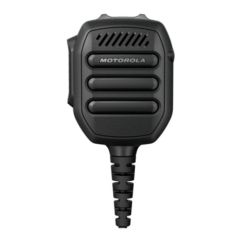
The NMN6247, NMN6250, and NMN6251 Public-Safety
Speaker/Microphones (PSSM) include a speaker, microphone,
push-to-talk (PTT) switch, high/low volume switch, swivel clip,
and cord connector assembly. All three models are exactly the
same, except that the PSSMs’ cord lengths are different:
NMN6247 is 30”, NMN6251 is 18”, and NMN6250 is 24”.
The PSSMs also have a threaded antenna jack located on top
of the housing, which accepts any of the following antennas:
II. PERFORMANCE TEST
A. General
The PSSM’s audio performance is designed to be similar to
that of the radio. The receive audio speaker loudness, with the
high/low switch on the PSSM set for “high,” will equal or
exceed the loudness of the radio speaker.
NOTE
The threaded antenna jack on the PSSM is not wired
as coaxial. Transmit power measurements should
read ZERO at this connector.
The threaded antenna jack (J2) on the PSSM is wired as center
and shield shorted together and connected to the radio
frequency (RF) coax cable center. The RF coax shield is
connected to printed circuit board (PCB) ground for best
radiation performance.
B. Audio test
The PSSM accessory can be checked for proper performance
by comparison with another new or known good unit on the
radio. Start each of the following two tests with the new or
known good unit on the radio, which must have an RF adapter
attached.
1. Microphone - Transmit to a communications monitor
while voicing a tone or the spoken word “four.” The
speaker/microphone should be held at a distance that
causes approximately 3kHz deviation (1.5kHz deviation
for 900Mhz radios). Repeat these conditions using the PSSM
to be tested. Good units compare to each other within
±2kHz deviation.
2. Speaker - Using the communications monitor, generate
an RF signal to the radio. Set the modulation to a 1kHz
tone at 3kHz deviation (1.5kHz deviation for 900Mhz
radios). Set the high/low switch on the PSSM to “high.”
Set the volume control on the radio to a loud, yet
undistorted, position. Without disturbing any settings,
repeat these conditions using the PSSM to be tested.
Good units should sound equally loud and undistorted.
The “low” setting loudness should compare as above.
C. Antenna test
Refer to Table 1 and verify that the proper antenna is being
used. Use one of the following to conduct this test:
• a communications monitor set to spectrum analyzer is
best,
• a monitor receiver set to threshold squelch, or
• a field strength meter.
© 1997, 1998 by Motorola, Inc.
Radio Products Group
8000 W. Sunrise Blvd., Ft. Lauderdale, FL 33322
Printed in U.S.A. 4/98. All Rights Reserved.
Table 1. Antennas
Antenna Frequency Description Insulator
Kit Number Color Code
NAE6546 UHF, 403-435 MHz 3" Helical RED
NAE6547 UHF, 435-470 MHz 3" Helical GREEN
NAE6548 UHF, 470-512 MHz 3" Helical BLACK
NOTES
•The antenna is not supplied with the PSSM kit; it
must be ordered separately.
•It is not recommended to use these PSSMs with VHF
radios, since radio performance is reduced.
•In shipping, a protective rubber seal (Motorola part
number 3205782P01) is inserted in the PSSM’s
antenna port. Use this seal to cover the microphone‘s
antenna port when not in use.
The public safety speaker/microphone (PSSM) includes a
3.5mm earphone jack (J1) located on top of the accessory
connector. A seal, which is attached to the accessory
connector, is provided to cover the earphone jack when it is
not in use.
When the PSSM is attached to the radio, the speaker in the
radio is disabled, and the receiver audio is connected to the
accessory speaker. Similarly, the accessory microphone is
connected to the transmitter, and the accessory PTT switch
can now control the PTT function of the radio. The radio
microphone and PTT switch are still operational, but since the
radio speaker is disabled, you can listen to the received audio
only through the accessory speaker.
CAUTION
!
2
Connect a new or known good PSSM to the radio, which must
have an RF adapter attached. Transmit to the equipment using
the microphone’s PTT by radiating to an input antenna on the
equipment at a distance that causes a mid-scale result. For a
receiver set for threshold squelch, set the squelch to just open
when transmitting. Next, connect the PSSM to be tested to
the radio, and transmit at the same distance as above. The
result should compare closely to the known good or new
microphone for field intensity.
III. HANDLING PRECAUTIONS
To avoid damage to circuits, observe the following handling,
shipping, and servicing precautions.
I. If the PSSM has been exposed to water, turn the unit so
that the speaker grille faces the ground and tap the unit
against your palm to remove any residual water. Blow out
any residual water from the microphone grille area before
operating the radio; otherwise, the sound may be
distorted until the water has evaporated from these areas.
J. For proper RF performance, avoid damage to, or
contamination of, the PSSM’s RF interface connector and
surrounding environmental seal. The RF interface
connector is located near the end of the curved arm that
protrudes from the top of the PSSM housing, and is the
portion that mates with the RF adapter on a properly
equipped radio.
IV. MAINTENANCE
Refer to the schematic diagram, the exploded view, and the
parts lists. Every part in the microphone is identified and
illustrated for assistance in removal and replacement.
If disassembly of the PSSM is required, do not reassemble it
without doing the following (numbers in parentheses refer to
item numbers in the exploded view).
•Remove the O-ring gasket (22) from the cover assembly
(16).
•Inspect the seal areas around the housing (1) and the
cover (16) for foreign material which might prevent the
O-ring gasket from sealing properly.
•Inspect O-ring gasket (22) and both cover screw O-ring
gaskets (18). If any of these are split, cracked, or damaged
in any way, discard and replace them.
•If the main printed circuit board (14) is removed, remove
the speaker spacer (27) and inspect the membrane of the
seal pad (28) for tears or holes. If the membrane is
damaged, remove it, being careful to remove all old
adhesive, and replace it with a new seal pad.
NOTE
When placing the seal pad (28), it is critical that
the small seal pad opening be aligned with the
microphone port in the housing.
•Tighten all hardware loosened or removed during
disassembly per the values listed in the Torque
Specifications table. Use the recommended torque driver
(RSX-4043A Rototorq Tool or equivalent).
If necessary, the external surfaces of the remote speaker
microphone may be cleaned with 0.5% solution of mild
dishwashing detergent in water (one teaspoon of detergent in
a gallon of water).
A. Prior to and while servicing a PSSM, particularly after
moving within the service area, momentarily place both
hands on a bare metal, earth-grounded surface. This will
discharge any static charge your body may have
accumulated.
B. Whenever possible, avoid touching any electrically
conductive part of the unit with your hands.
C. Because they contribute to static buildup, avoid carpeted
areas, dry environments, and certain types of clothing
(silk, nylon, etc.) when servicing a unit.
D. All electrically powered test equipment should be
grounded. Apply the ground lead from the test
equipment to the unit before connecting the test probe.
Similarly, disconnect the test probe prior to removing the
ground lead.
E. If the microphone cartridge is removed from the unit,
place it on a conductive surface, such as a sheet of
aluminum foil which is connected to ground through
100k ohms of resistance.
F. When soldering, be sure the soldering iron is grounded.
G. Prior to replacing circuit components or touching the
microphone cartridge, be sure to discharge any static
buildup. Since voltage differences can exist across the
human body, it is recommended that only one hand be
used if it is necessary to touch the microphone cartridge
and associated wiring.
H. Replacement microphone cartridges should be kept in
conductive packaging until they are placed in the unit.
Torque Torque Torque
Application (In. Lbs.) (N•m) Bit No.
Cover Screws 6 0.68 6680321B78
PC Board Screws 3 0.34 6680321B78
Clip Screws 4 0.45 6680321B78
Toggle Switch Boot 3 0.34 6680370B99
Connector Assembly 3 0.34 6680381B69
Screw
Ear jack Spanner 3 0.34 6680370B89
Antenna Spanner 20 1.13 6680370B90
Retaining Nut 7 .079 6680370B90
!
Wearing a conductive wrist strap (Motorola No. RSX-
4015A) will minimize static buildup during servicing.
When wearing a conductive wrist strap, be
careful near high voltage sources. The good
ground provided by the wrist strap will also
increase the danger of lethal shock from
accidentally touching high-voltage sources.
!
If the aluminum foil is connected directly to
ground, be cautious of possible electrical shock
from contacting the foil and other electrical
circuits at the same time.
WARNING
WARNING
Table 2. Torque Specifications
3
REFERENCE MOTOROLA
SYMBOL PART NO. DESCRIPTION
Electrical Parts List
COIL, RF: unless stated
L1,2 2462575A04 Choke, 1µH
L3 thru 6 2462587Q44 Choke, 0.56µH
LS1 5005213W01 SPEAKER: 1 3/4"; 28½
MK1 5005227J06 MICROPHONE: Electret
SWITCH:
S1 3905834K07 Dome, PTT
S2 4005680K04 Toggle
VR1, 2 4880140L14 DIODE: Zener, 9.1V (See Note)
C1
0.1µF
R2 150
R1 150
C2
.022µFC3
82pF C4
330pF VR1
9.1V
MK1
PTT
S1
MICROPHONE HEAD
L2
1µH
J2
4
3
5
2
1
L6
560nH
L4
C6
1pF
C5
560pF
L3
COAX COAX
BLK BLK
GND
WHT WHT
GND
EXT ANT
PTT
EXTERNAL
L1
1µHEXT MIC
MIC
CORD
GRN GRN
LS1 BLU BLU
SIDE
VIEW
OF
RADIO
CONNECTOR
RED RED
SPKR
SPKR
1
RF
GND
3
5
7
9
11
2
2
L5
0.56nH
0.56nH
0.56nH
6
3
1
8
4
6
8
10
12
13
S2 1
23HI
LO J1
MAEPF-25767-O
5
CAPACITOR, Fixed: pF±5%; 63V
unless stated
C1 2113741B69 0.1µF
C2 2184008H19 .022µF
C3 2113740A53 82
C4 2113740A67 330
C5 2113740A73 560
C6 2113740A03 1
JACK:
J1 0905100W01 Micro, 3.5mm
J2 - - - - - - - - - - Mechanical parts; items 2, 3, 5, 6,
8, 9, and 10 on exploded view
J3 0905830Z01 Connector, Coaxial SMT Note: For optimum performance, order replacement diodes by Motorola part
number only.
J3
4
Exploded View Parts List
ITEM MOTOROLA
NO. PART NO. DESCRIPTION
1 0104007J20 ASSEMBLY, Housing, Mic Head (includes
items 28, 29, and 31)
2 0405534U01 WASHER
3 4305533U01 BUSHING, Antenna
4 0205791P01 NUT, Toggle Seal
5 2900005369 LUG
6 3205560U01 SEAL, Rubber
7 - - - - - - - - - - ANTENNA, Typical
8 0305559U01 SCREW, Pin
9 0205543E03 NUT, Spanner
10 0405327S01 WASHER, Bearing
11 7582154D33 PAD, Speaker
12 1405490Q02 BOOT, Microphone
13 SEE NOTE MICROPHONE
14 8405194S01 PRINTED CIRCUIT BOARD, Main
15 0300139047 SCREW, Cutting
16 0105955P12 ASSEMBLY, Cover
17 3305706X58 LABEL, Kit Number (NMN6247)
or 3305706X59 LABEL, Kit Number (NMN6250)
or 3305706X60 LABEL, Kit Number (NMN6251)
18 3205082E03 GASKET, O-Ring (2 req’d)
19 0382210E19 SCREW, Cover-Captive; #4-40 (2 req’d)
20 0300139982 SCREW, Machine #2-56x.188" (4 req’d)
21 0105957Q44 ASSEMBLY, Belt Clip
22 3205082E63 GASKET, O-Ring
23 SEE NOTE DOME, PTT (S1)
34
13
12
14
1
4
6
2
33
9
7
8
5
24
23
3
10
11
15
16
36
17
29
19 35 18
30
29
28
26 27
20 21
25
31
22
MAEPF-25768-A
39
38
40
32
47 48
51
49
50
37
43
44
42
41
45
Note: Refer to Electrical Parts List for part number and description.
24 3205264L06 SEAL, PTT
25 8405296R03 PRINTED CIRCUIT BOARD, PTT
26 SEE NOTE SPEAKER (LS1)
27 4305407R01 SPACER, Speaker
28 3205190R05 PAD, Seal
29 7505136L03 PAD, Silicon Sponge (2 req’d)
30 SEE NOTE SWITCH, Toggle (S2)
31 4505211R02 LEVER, PTT
32 1386324A01 ESCUTCHEON
33 3305269R01 LABEL, Nameplate
34 8405213S01 PRINTED CIRCUIT, Flexible
35 0405465C01 WASHER, PLASTIC (2 req’d)
36 2900003025 LUG
37 SEE NOTE JACK, Micro (J1)
38 0104007J22 ASSEMBLY, Printed Circuit Board
39 6405241X01 BASEPLATE
40 3205235W01 GASKET
41 3205756Z01 SEAL, Earphone Jack
42 0305731J20 SCREW
43 - - - - - - - - - - part of item 37
44 - - - - - - - - - - CABLE and CONNECTOR; factory test
required, not field repairable
45 0205770Z02 NUT, Retaining
46 3205082E05 O-Ring
47 2805805Z01 ASSEMBLY, RF Connector
48 3205769Z01 ASSEMBLY, Plunger Seal
49 5505737Z01 LATCH
50 2205541V01 PIN
51 4105538V01 SPRING

This manual suits for next models

3

Other Motorola Speakers manuals

Motorola PMMN4131 User manual

Motorola

Motorola PMMN4131 User manual

Motorola Sonic Play 100 User manual

Motorola

Motorola Sonic Play 100 User manual

Motorola ROKR 800 User manual

Motorola

Motorola ROKR 800 User manual

Motorola ROKR 820 User manual

Motorola

Motorola ROKR 820 User manual

Motorola HSN1006A User manual

Motorola

Motorola HSN1006A User manual

Motorola EQ5 - MOTOROKR User manual

Motorola

Motorola EQ5 - MOTOROKR User manual

Motorola NSN6054A User manual

Motorola

Motorola NSN6054A User manual

Motorola BLUETOOTH T305 PORTABLE HANDS-FREE SPEAKER User manual

Motorola

Motorola BLUETOOTH T305 PORTABLE HANDS-FREE SPEAKER User manual

Motorola RMN5072 User manual

Motorola

Motorola RMN5072 User manual

Motorola Sphere User manual

Motorola

Motorola Sphere User manual

Motorola 89242N - EQ5 - Bluetooth hands-free... User manual

Motorola

Motorola 89242N - EQ5 - Bluetooth hands-free... User manual

Motorola Power-Voice TSN6015A Guide

Motorola

Motorola Power-Voice TSN6015A Guide

Motorola HF800 - Bluetooth hands-free Speakerphone User manual

Motorola

Motorola HF800 - Bluetooth hands-free Speakerphone User manual

Motorola EQ5 User manual

Motorola

Motorola EQ5 User manual

Motorola Sonic Play 200 User manual

Motorola

Motorola Sonic Play 200 User manual

Motorola ROKR 500 User manual

Motorola

Motorola ROKR 500 User manual

Motorola HSN4035 Operating instructions

Motorola

Motorola HSN4035 Operating instructions

Motorola DECK ULTRA User manual

Motorola

Motorola DECK ULTRA User manual

Motorola Deck User manual

Motorola

Motorola Deck User manual

Motorola Sonic Play+ 275 User manual

Motorola

Motorola Sonic Play+ 275 User manual

Motorola ROKR 810 User manual

Motorola

Motorola ROKR 810 User manual

Motorola ROKR 800 User manual

Motorola

Motorola ROKR 800 User manual

Motorola MD100X User manual

Motorola

Motorola MD100X User manual

Motorola Sphere User manual

Motorola

Motorola Sphere User manual

Popular Speakers manuals by other brands

Celestion TN range TN1525 Specifications

Celestion

Celestion TN range TN1525 Specifications

Phase-Tech CS PROFESSIONAL CS-6R owner's manual

Phase-Tech

Phase-Tech CS PROFESSIONAL CS-6R owner's manual

Craig cma3561 owner's manual

Craig

Craig cma3561 owner's manual

ITC T-778H owner's manual

ITC

ITC T-778H owner's manual

CyberData 011121 Installation quick reference

CyberData

CyberData 011121 Installation quick reference

Party Light & Sound NEBULA user manual

Party Light & Sound

Party Light & Sound NEBULA user manual

iLive ISBW105BU user guide

iLive

iLive ISBW105BU user guide

Logitech Z506 Getting started guide

Logitech

Logitech Z506 Getting started guide

nedis FSBS110AT quick start guide

nedis

nedis FSBS110AT quick start guide

Insignia NS-CSPBTF1 quick start guide

Insignia

Insignia NS-CSPBTF1 quick start guide

Manhattan Sound Science Atom manual

Manhattan

Manhattan Sound Science Atom manual

Phase CI110 II owner's manual

Phase

Phase CI110 II owner's manual

LG FJ3 Simple manual

LG

LG FJ3 Simple manual

ELAC Carina BS243.4 operating instructions

ELAC

ELAC Carina BS243.4 operating instructions

Acoustic Research AW826 Installation and operation manual

Acoustic Research

Acoustic Research AW826 Installation and operation manual

Wonders Technology DS-827B manual

Wonders Technology

Wonders Technology DS-827B manual

Audibax FREEPORT212 user manual

Audibax

Audibax FREEPORT212 user manual

Gear4 Xorb Wireless 2.1 user manual

Gear4

Gear4 Xorb Wireless 2.1 user manual

manuals.online logo
manuals.online logoBrands
  • About & Mission
  • Contact us
  • Privacy Policy
  • Terms and Conditions

Copyright 2025 Manuals.Online. All Rights Reserved.