Mountain MTN5520 User manual

MTN5520 1 rev. 02/04/03
Model 1006A
6 TON
CAPACITY
RATCHETING
JACK STAND
Model 1006A
6 TON
CAPACITY
RATCHETING
JACK STAND
FOR YOUR SAFETY & TO PREVENT INJURY:
USE ONLY ON HARD LEVEL SURFACES.
DO NOT GET UNDER A VEHICLE THAT IS ONLY SUPPORTED BY A
TROLLEY/SERVICE JACK–USE VEHICLE SUPPORT STANDS.
THIS IS A LIFTING DEVICE ONLY. DO NOT MOVE OR DOLLY THE
VEHICLE WHILE ON THE JACK. IMMEDIATELY AFTER LIFTING,
SUPPORT THE VEHICLE WITH APPROPRIATE MEANS.
DO NOT OVERLOAD. OVERLOADING CAN CAUSE DAMAGE TO OR
FAILURE OF THE JACK.
LIFT ONLY ON AREAS OF THE VEHICLE AS SPECIFIED BY THE
VEHICLE MANUFACTURER.
CENTER LOAD ON SADDLE PRIOR TO LIFTING. OFF-CENTER LOADS
MAY CAUSE DAMAGE TO JACK, LOSS OF LOAD, PROPERTY
DAMAGE, PERSONAL OR FATAL INJURY.
NO ALTERATIONS TO THE JACK SHALL BE MADE.
READ, STUDY AND UNDERSTAND THE OPERATING MANUAL
PACKED WITH THIS JACK BEFORE OPERATING.
FAILURE TO HEED THESE WARNINGS MAY RESULT IN LOSS OF
LOAD, DAMAGE TO JACK, AND/OR FAILURE RESULTING IN
PROPERTY DAMAGE, PERSONAL OR FATAL INJURY.
THIS OPERATING MANUAL CONTAINS
IMPORTANT SAFETY INFORMATION.
READ CAREFULLY AND UNDERSTAND
ALL INFORMATION BEFORE
OPERATING TOOL. SAVE THIS
MANUAL FOR FUTURE USE.
Features:
• Chrome Plated Lift Ram
• Self-Retracting Ram Springs for Fast Ram Retraction
• Push Valve Lever for Fast Air Control
• 3 Position Lock Lever
• Safety Overload Valve
• Large Diameter Wheels for Ease of Operation
Owner/User Responsibility:
The owner and/or user must have a thorough understanding of the
manufacturer’s operating instructions and warnings before using
the service jack. Personnel involved in the use and operation of
equipment shall be careful, competent, trained, and qualified in the
safe operation of the equipment and its proper use when servicing
motor vehicles and their components. Warning information should
be emphasized and understood. If the operator is not fluent in
English, the manufacturer’s instructions and warnings shall be read
to and discussed with the operator in the operator’s native language
by the purchaser/owner, making sure that the operator
comprehends its contents.
Owner and/or user must study and maintain for future reference
the manufacturer’s instructions and pertinent warning information.
Owner and/or user is responsible for keeping all warning labels
and instruction manuals legible and intact. Replacement labels and
literature are available from the manufacturer.
MTN5520
22 Ton Air/Hydraulic Jack
ALWAYS
Support Vehicle with
Appropriately Rated
Support Stands!
Use Service Jack
for Lifting Purposes
ONLY!
SPECIFICATIONS:
Capacity . . . . . . . . . . . . . . . . . . . . . . . . . . 22 Tons
Min. Saddle Height . . . . . . . . . . . . . . . . . . . . . . . 9"
Max. Saddle Height . . . . . . . . . . . . . . . . . . . . . .17"
Stroke . . . . . . . . . . . . . . . . . . . . . . . . . . . . . 4-3/4"
Handle Length . . . . . . . . . . . . . . . . . . . . . . . . . 49"
Wheel Diameter . . . . . . . . . . . . . . . . . . . . . . . . . .8"
Dimensions . . . . . . . . . . . . . . .21"L x 13"W x 56"H
Air Pressure . . . . . . . . . . . . . . . . . . . . . . . . . .90 psi

MTN5520 2 rev. 02/11/03
Assembly Instructions:
This jack comes pre-assembled, except for the handle. The handle is
a two piece handle. Align the thru hole of the upper and lower
piece, and insert (2) M6 allen bolts. Align through hole on the three
position lock lever and insert Phillip screw.
Inspection:
Visual inspection should be made before each use of the service
jack, checking for leaking hydraulic fluid and damaged, loose or
missing parts. Each jack must be inspected by a manufacturer’s
repair facility immediately, if accidentally subjected to an abnormal
load or shock. Any jack which appears to be damaged in any way,
found to be badly worn, or operates abnormally MUST BE
REMOVED FROM SERVICE until necessary repairs are made
by a manufacturer’s authorized repair facility. It is recommended
that an annual inspection of the jack be made by a manufacturer’s
authorized repair facility and that any defective parts, decals or
warning labels be replaced with manufacturer’s specified parts.
A list of authorized repair facilities is available from the
manufacturer.
Maintenance:
To Add Oil: With saddle fully lowered and ram depressed, set jack
in an upright position and remove oil filler plug. Fill until oil is level
with filler plug hole.
To Change Oil: For best performance and longest life, replace the
complete oil supply at least once a year. To drain the oil, remove the
filler plug. Lay the jack on its side and allow the oil to run out into
suitable drain pan. The oil will run slowly because air must enter as
oil drains out. Be careful to prevent dirt or foreign matter from
entering the system. Replace with proper oil.
IMPORTANT! Use only a good grade hydraulic fluid. Avoid
mixing types of oil. Do not use brake fluid, alcohol, glycerin,
transmission fluid, or dirty oil. Improper fluid can cause serious
internal damage to the jack, rendering it inoperative.
Operating Instructions:
IMPORTANT: Before attempting to raise a vehicle, check vehicle
service manual for recommended lifting surfaces.
1. To raise load: Close release valve tightly (by turning handle
clockwise).
DO NOT OVERTIGHTEN.
Position jack under load so
that saddle will contact load firmly and load is centered so it cannot
slip. Operate the air valve until saddle approaches the load. Once
again check to see that saddle is correctly positioned. Raise load to
desired height. Place jack stands of appropriate capacity under the
vehicle. DO NOT CRAWL UNDER VEHICLE WHILE LIFTING
VEHICLE OR PLACING OR REMOVING JACK STANDS!
Place jack stands at vehicle manufacturer’s recommended lift areas
that provide stable support for the raised vehicle.
2. To lower load: Open release valve VERY SLOWLY (by turning
handle counterclockwise). When release valve is opened, saddle
and load will be lowered. Lower the vehicle slowly so as not to shock
load the jack stands. Once repairs are completed, raise vehicle
enough to remove jack stands. Lower vehicle very slowly.
CAUTION: Keep hands or feet away from the hinge mechanism of
the jack.

MTN5520 3 rev. 02/04/03
Troubleshooting:
SOLUTION
The release valve is not closed.
✔Turn the valve clockwise tightly.
Low on hydraulic fluid.
✔✔ Refill the jack to the correct level of
hydraulic fluid.
Pump seals and back-up ring are defective.
✔Clean hydraulic fluid passages, replace seals
and renew hydraulic fluid.
(Must be serviced by qualified service center)
The hydraulic system is filled with air. Open
✔✔the release valve, pump handle rapidly (4)
full strokes to purge air, close release valve.
Return spring is broken or linkages binding.
✔Replace spring if broken. Grease pivot shaft,
oil all lift arm linkages.
Discharge ball is not sealing hydraulic system
and oil may be dirty. Manually flush
hydraulic system by raising and lowering lift
✔arm by hand. Open the release valve, as
required to raise and lower the lift arm.
Manually raise and lower lift arm.
PROBLEM
Jack will not lift load
Jack will not hold load
or handle rises
Jack will not lift to
its full height
Jack will not lower
completely
Jack will not lift smoothly
or jack feels spongy
MTN5520 4 rev. 02/11/03
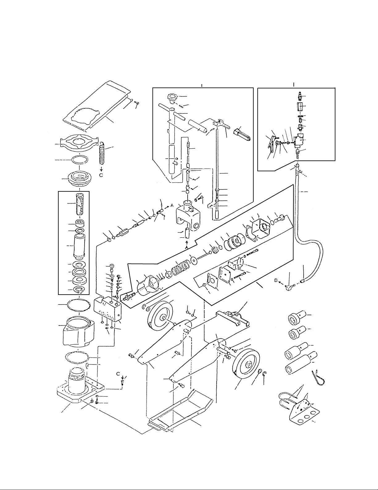
10-26
10-25
10-24
10-22
10-23
10-7
10-5
10-6
10-9
10-8
10-10
10-16
10-14
10-15
10-16
10-12
12-1
12-2
12-3
12-4
12-9
12-7
12-5
12-8
12-6
1-4
1-2
1-3
1-1
6-3
6-14
6-12
6-15
6-9
6-1
6-1
6-9
6-14
6-12
1-3
1-2 7-5 7-6
7-7 7-8
7-11
7-4
7-3
7-13
7-2
7-12
7-1
8-13
5-9
5-5
5-6
5-22
5-2
5-4
5-1
5-9
5-21
5-7
5-3
5-14
5-20
5-18
5-13
5-16
5-11
5-12
4.4 4.6
5-17
4-5
4-11
4-9
4-2
4-1
4-3
4-8
4-10
3-4
2-31
2-19
2-20 3-2
3-12
3-10
2-19
2-25
2-23
3-14
3-13
2-24
2-8
2-7
2-2
2-32
2-1
2-5
2-4
2-3
2-17
2-18
2-22 2-21
6-7
6-6
6-8
2-12
2-13
2-29
2-14
3-8
3-5
3-6
3-9
3-7
5-15
7-0
Air Pump Ass’y
4-0
Release Valve Ass’y
2-0
Piston
Rod
Ass’y
5-0
Handle Ass’y
10-30
Air Valve Ass’y
5-8
5-9
5-19
8-12
8-11
8-10
8-9
8-8
8-7
8-6
8-5
8-4
8-3
8-2
8-14 7-10
7-9
1-4
6-13
6-13
10-4
10-3
10-2
10-1
10-13
2-15
8-1
2-16

MTN5520 5 rev. 02/04/03
Item Part
No. No. Description Qty.
1-1 Wheel Shaft 2
1-2 RS66221-2 Washer 2
1-3 RS66221-3 Wheel 2
1-4 RS66221-4 Snap Ring 2
2-0 RS66222-0 Piston Rod Ass’y 1
2-1 Piston Rod 1
2-2 Packing 1
2-3 Screw 1
2-4 Bush 1
2-5 Snap Ring 1
2-7 Packing Retainer 1
2-8 RS66222-8 Cylinder 1
2-12 Bolt 2
2-13 Packing 2
2-14 Spring Retainer 1
2-15 Safety Valve 1
2-16 Spring 1
2-17 Nut 1
2-18 Oil Seal 1
2-19 O Ring 2
2-20 Oil Tank 1
2-21 RS66222-21 Spring 4
2-22 RS66222-22 Spring Hanger 1
2-23 Machine Screw 4
2-24 Nut 4
2-25 Oil Strainer 1
2-29 Packing 1
2-31 Snap Ring 1
2-32 Back-up Ring 1
3-2 Oil Box 1
3-4 Bolt 1
3-5 Spring 1
3-6 Steel Ball 1
3-7 Steel Ball 1
3-8 Copper Packing 1
3-9 Separator 1
3-10 Back-up Ring 1
3-12 O Ring 3
3-13 Bolt 3
3-14 Spring Washer 3
4-0 RS66224-0 Release Valve Ass’y 1
4-1 Valve 1
4-2 O Ring 1
4-3 Guide 1
4-4 Universal Joint 1
4-5 Spring Pin 1
4-6 Spring Pin 1
4-8 O Ring 1
4-9 Washer 1
4-10 Packing 1
4-11 Snap Ring 1
5-0 RS66225-0A Handle Ass’y - 2 piece 1
5-1 Handle 1
5-2 RS66225-2 Knob 1
5-3 Connecting Rod 1
5-4 Spring Pin 1
5-5 RS66225-5 Stopper (incl. 5-8, 5-9, 5-19) 1
5-6 Lock Lever 1
5-7 Spring Pin 1
5-8 Spring 1
5-9 Washer 3
5-11 RS66225-11 Handle Fork 1
5-12 Bolt 1
5-13 Spring Washer 1
5-14 Connecting Rod 1
5-15 Connecting Rod 1
5-16 Universal Joint 1
5-17 Spring Pin 1
5-18 Spring Pin 1
5-19 Spring Pin 1
5-20 Cotter Pin 1
Item Part
No. No. Description Qty.
5-21 Handle Cap 2
5-22 Handle Cap 1
6-1 Handle Fork Bracket 2
6-3 Frame 1
6-6 RS66226-6 Upper Cover 1
6-7 Machine Screw 4
6-8 Lock Washer 4
6-9 Bolt 4
6-12 Bolt 4
6-13 Bolt 4
6-14 Spring Washer 4
6-15 Lower Cover 1
7-0 RS66227-0 Air Pump Ass’y 1
7-1 Packing Washer 1
7-2 Muffler Cover 1
7-3 O Ring 23.6 x 3.55 1
7-4 Valve Rod 1
7-5 Rubber Pad 1
7-6 Packing Washer 1
7-7 Cover 1
7-8 Spring Washer 1
7-9 Hex Socket Screw M8 x 70 4
7-10 Filter Element 1
7-11 Filter Cover 1
7-12 ø2.5 Steel Ball 1
7-13 ø6 Steel Ball 2
8-1 RS66228-1 Plunger Cover 1
8-2 Air Pump Body 1
8-3 NL Retainer 1
8-4 O Ring 11.2 x 2.65 1
8-5 Packing Guide 1
8-6 Nut 1
8-7 Spring 1
8-8 Washer 1
8-9 Plunger 1
8-10 Retainer 1
8-11 O Ring 25 x 3.55 1
8-12 O Ring 56 x 5.30 2
8-13 Piston 1
8-14 ø3 Steel Ball 2
10-30 RS662210-30 Air Valve Ass’y 1
10-1 Valve Body 1
10-2 Nut 1
10-3 O Ring 1
10-4 O Ring 1
10-5 Packing 1
10-6 Throttle 1
10-7 Spring 1
10-8 Lever 1
10-9 Lever Pin 1
10-10 Lock Lever 1
10-12 Pump Elbow 1
10-13 Hose Connector 1
10-14 Spring 1
10-15 RS662210-15 Air Hose 1
10-16 Hose Band 2
10-22 Air Filter 1
10-23 Connector 1
10-24 O Ring 1
10-25 Connecting Nut 1
10-26 Connector 1
12-1 RS662212-1 Adaptor-A 70 x 20 1
12-2 RS662212-2 Adaptor-B 50 x 20 1
12-3 RS662212-3 Adaptor C 50 x 50 1
12-4 RS662212-4 Adaptor D 50 x 100 1
12-5 RS662212-5 Holder Adaptor 1
12-6 U-Bolt 2
12-7 Nut 4
12-8 Spring Washer 4
12-9 RS662212-9 Hitch Pin 4
Note: only items identified by part number are available
individually.
* Available only in the seal kit, part # RS6622-SK
*
*
*
*
*
*
*
*
*
*
*
*
*
*
*
*
*
*
*
*
*
*
*
*
*
*
*
*
*
*
*
*
*
*
Table of contents
Other Mountain Jack manuals


Popular Jack manuals by other brands


Craftsman
Craftsman 48112 Operator's manual

Meec tools
Meec tools 012149 operating instructions

Meganex
Meganex MEG11 instruction manual

Blitz
Blitz XLift 2,6 user guide

Harbor Freight Tools
Harbor Freight Tools BADLAND 58395 Owner's manual & safety instructions

AME
AME 14400 Instruction manual & parts breakdown

OEM Tools
OEM Tools 24793 Operating instructions and parts manual

OEM Tools
OEM Tools 24856 Operating instructions and parts manual

Titan
Titan EZM-1500 Installation, operation & maintenance manual

Draper
Draper 53089 user manual

kincrome
kincrome K12150 Owner's assembly and operating manual

Performance Tool
Performance Tool W1627 owner's manual