– 4 – – 5 – – 6 –
www.moxa.com/support
+1-714-528-6777 (toll-free: 1-888-669-2872)
+86-21-5258-9955 (toll-free: 800-820-5036)
2013 Moxa Inc., All Rights Reserved
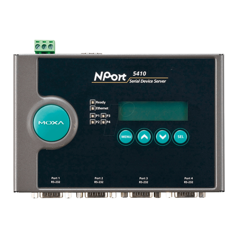
There are four push buttons on the CN2600 nameplate. Going from
left to right, the buttons are:
MENU menu
Activates the main menu, or returns to an
upper level.
Scrolls up through a list of items shown on the
LCM panel’s second line.
Scrolls down through a list of items shown on
the LCM panel’s second line.
SEL select
Selects the option listed on the LCM panel’s
second line.
Use the buttons to access the CN2600’s function menus. As you
move through the various functions and setting options, note that
the top line shows the current menu or submenu name, and the
bottom line shows the submenu name or menu item. Press the SEL
button to access the item displayed on the bottom line.
Refer to CN2600 series User’s Manual for more details.
Hardware Installation
Installing the CN2600
Open the package, and attach the CN2600 to a desktop, or fasten
it to the rack cabinet.
Wiring Requirements
1. Use separate paths to route wiring for power and devices. If
power wiring and device wiring paths must cross, make sure
the wires are perpendicular at the intersection point.
2. NOTE: Do not run signal or communication wiring and power
wiring in the same wire conduit. To avoid interference, wires
with different signal characteristics should be routed
separately.
3. Where necessary, we strongly advise labeling wiring to all
devices in the system.
Connecting the Power
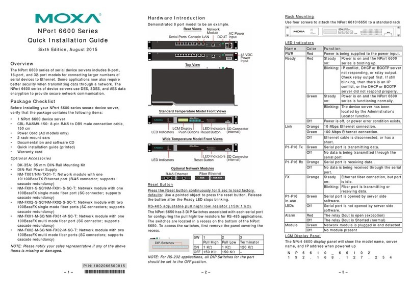
AC: Connect the CN2600 100-240 VAC power line with its AC
connector. If the power is properly supplied, the “Ready” LED will
show a solid red color until the system is ready, at which time the
“Ready” LED will change to a green color.
Connecting to the Network
Connect one end of the Ethernet cable to the CN2600’s 10/100M
Ethernet port and the other end of the cable to the Ethernet
network. There are 2 LED indicators located on the top left and
right corners of the Ethernet connector. If the cable is properly
connected, the CN2600 will indicate a valid connection to the
Ethernet in the following ways:
The top right corner LED indicator maintains a solid
green color when the cable is properly connected to a
100 Mbps Ethernet network.
The top left corner LED indicator maintains a solid
orange color when the cable is properly connected to a
10 Mbps Ethernet network.
Connecting to a Serial Device
Connect the serial data cable between the CN2600 and the serial
device.
Connecting to a Console
A console is a combination of keyboard and monitor, and is used to
configure settings and to monitor the status of your system. If you
do not have a network environment, use a terminal, a PC running
UNIX, or a PC with terminal emulation software (e.g.,
HyperTerminal in Windows; PComm by Moxa). Use an
RJ45-to-DB25 or RJ45-to-DB9 cable to connect the terminal to the
console socket. Refer to the CN2600 User’s Manual for more
details.
Software Installation
Entering the Console Utility
The Console Utility is the main application needed to set up the
server/port configuration, and to execute utilities such as ping,
diagnosis, monitor, and upgrade. There are two ways to enter the
Console Utility. One is to use terminal emulation through a console
terminal, and the other is to telnet from a network terminal.
Refer to the CN2600 User’s Manual for more details.
Pin Assignments and Cable Wiring
10/100BaseTX Port Pinouts
-232/422/485 Port
male) RS-232/422/485 Port
Specifications
100 to 240 VAC, 47 to 63 Hz
235 mA for 100 V
145 mA for 240 V
Standard Models: 0 to 60°C (32 to 140°F)
Wide Temp. Models: -40 to 75°C (-40 to 167°F)
-20 to 70°C (-4 to 158°F), 5 to 95% RH
198 × 45 × 440 mm (7.8 × 1.77 × 17.3 in)
Standards and Certifications
CE: EN55022 Class A/EN55024
FCC: FCC part 15 subpart B, Class A
