manuals.online logo
Brands
  1. Home
  2. •
  3. Brands
  4. •
  5. Sensitron
  6. •
  7. Gas Detector
  8. •
  9. Sensitron SMART3 NC User manual

Sensitron SMART3 NC User manual

Pag. 1
Manuale installazione rapido / Short installation manual
MT4811 rev.2 05/08/2022
SMART3 NC
Manuale installazione rapido / Short installation manual
ETICHETTA IDENTIFICATIVA IDENTIFICATION LABEL
LINK MANUALE PRINCIPALE
Manuale d’uso rilevatori SMART3 NC
Technical manual for SMART3 NC gas detectors
ST/*/*/N1; ST/*/*/N2; ST/*/*/N3; ST/*/*/S1; ST/*/*/S2; ST/*/*/S3;
ST/*/*/C1; ST/*/*/C2; ST/*/*/C3
ATEX marking and additional information label
The fields marked with [..] are compiled according to instructions on page 3.
ST/[1]/[2]/[3]
Ex db IIC [4] Gb
[5] ≤ Ta ≤ [6]
CESI yy ATEX nnnX
WARNING: Do not open when energized
Thread [8]
Label characteristics
Material: 3M 3812, 3M HiPerformance, Roll cover part number: 157001 or equivalent
Dimensions: 22 x 50 mm or bigger
0722
II 2 G
Vmax 27,6 Vdc
Pmax [7]
Year YYYY
Gas detector: [part number] SN:[serial number]
F.S.: [full scale value]
Volt: 12-24 Vdc
Date: YYYY/MM
Line: [product line]
CESI nn ATEX nnnX
Logo in colour or in
black and white
Sensitron S.r.l. ITALY
Viale della Repubblica, 48 – 20010 Cornaredo (MI)
Gas: [gas]
Adj. with: [gas]
Curr: [current]
Output: [output type]
QR code
Doc. number
MEEX3937
Page 1 of 4
Rev. Description Prepared by / Date Checked by / Date Approved by / Date
0ATEX marking details Å. Hellstrand 26/07/2017 Å. Hellstrand 26/07/2017 G. Frigo 26/07/2017
1Updated standard revision Å. Hellstrand 04/12/2019 Å. Hellstrand 04/12/2019 G. Frigo 04/12/2019
2Label revision S. Colombo 05/05/2020 S. Colombo 05/05/2020 G. Frigo 05/05/2020
Esempio di etichetta del rilevatore da compilare / Example of gas detector label to be lled
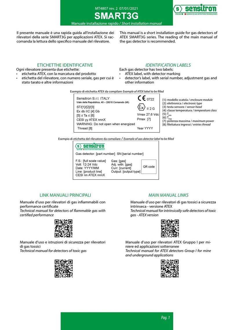
Il presente manuale è una rapida guida all’installazione dei
rilevatori della serie SMART3 NC, impiegati per rilevare la
presenza di sostanze combustibili (%LEL) e tossiche (ppm)
in aree sicure. Si raccomanda la lettura dello specico ma-
nuale del rilevatore.
Ogni rilevatore presenta un’ etichetta, con numero seriale,
gas per cui è stato tarato e altre informazioni.
MAIN MANUAL LINKS
This manual is a short installation guide for gas detectors of
SMART3 NC series, used to detect the presence of combu-
stible (%LEL) and toxic (ppm) gases in non classied areas.
The reading of the main manual of the gas detector is re-
commended.
Each gas detector has a label with serial number, adjustment
gas and other information.
LINK MANUALI ACCESSORI
Scheda RS485
RS485 board
Scheda 3 relè
3 relays board
Scheda 1 relè
1 relays board
Tastierino di calibrazione
Calibration keypad
Display LED Display OLED
Protocollo modbus
Modubus protocol
ACCESSORIES MANUAL LINKS
Kit di calibrazione
Calibration kit
Pag. 2
Manuale installazione rapido / Short installation manual
MT4811 rev.2 05/08/2022
SMART3 NC
Durante le operazioni di montaggio e installazione, gli im-
pianti devono essere messi in sicurezza. Inoltre è opportuno
tenere in considerazione alcune norme generali, quali:
• Si raccomanda di non installare rivelatori gas nelle vici-
nanze di prese d’aria e/o ventilatori che provocano forti
correnti d’aria.
• I rivelatori non devono essere altresì posti in zone nel-
le quali siano presenti vibrazioni e, sebbene immuni da
disturbi a radiofrequenze è consigliabile non installarle
in prossimità di emettitori radio (ponti radio o apparec-
chiature simili).
• Altra buona norma è quella di installare il rivelatore in
zone facilmente accessibili per le operazioni di test e ta-
ratura e per l’inserimento dell’adattatore del kit di cali-
brazione.
• GPL, Vapori di benzina, COe NOsono gas più pesanti
dell’aria. Disperdendosi stazioneranno nella parte bassa
dell’ambiente ed il rivelatore deve quindi essere posizio-
nato a 30 cm dal pavimento. Il CO ha un peso specico
simile a quello dell’aria; è un gas molto tossico e per una
protezione ottimale il rivelatore deve essere installato
alla altezza della respirazione, quindi a circa m 1.60 dal
pavimento. Il metano è un gas più leggero dell’aria e, di-
sperdendosi nell’ambiente, tenderà a salire verso l’alto;
il rivelatore deve quindi essere posizionato a 30 cm dal
sotto per ottenere un ecace intervento.
PREDISPOSIZIONE SITO DI INSTALLAZIONE
INSTALLAZIONE
Modalità per il corretto montaggio:
Il rivelatore deve sempre essere installato con l’elemento
sensibile (testa di rivelazione) rivolta verso il basso. Il conte-
nitore del rivelatore per nessuna ragione deve essere forato.
Per il ssaggio a muro, utilizzare i tasselli da 6x40 mm secon-
do le distanze riportate nella gura sottostante.
INSTALLATION SITE PREARRANGEMENT
INSTALLATION
At the mounting and installation phase be sure all safety
precautions have been considered. Always consider how im-
portant it is the correct positioning of gas detectors to get
the optimum response.
• Be careful never to install gas detectors close to air inta-
kes or fans causing strong air currents.
• Be sure the detectors are attached to a rm base to pre-
vent vibration that can damage them, producing unre-
liable results.
• Although the electronics comply with the electromagne-
tic compatibility rules, it is advised to keep the detectors
at a distance from any radio frequency senders (such as
radio links or similar).
• Please be also sure that detectors are placed in a con-
venient location for future maintenance and calibration
requirements.
• LPG, petrol vapours, COand NOare gases heavier than
air and tend to spread downwards; the detector should
be placed at 30 cm from the oor to maximise the eecti-
veness of the detection. CO has a specic weight simi-
lar to air’s; it is a very toxic gas and to get a reliable pro-
tection, the detector should be placed at the breathing
level, approximately 1.60m above the oor. Methane is
a gas lighter than air and it tends to spread upwards; the
detector should be placed at 30 cm from the ceiling in
order to maximise the eectiveness of the detection.
Correct positioning mode:
The gas detector is always to be mounted with the sensing
element placed downward. For no reasons at all the enclo-
sure can be drilled.
During installation step, the user has to x the detector with
two plugs of 6x40 mm. The plugs must be positioned fol-
lowing the distancies described in the following gure.
100 mm
100 mm
108 mm
Pag. 3
Manuale installazione rapido / Short installation manual
MT4811 rev.2 05/08/2022
SMART3 NC
Schema topograco del circuito: Detector circuit layout:
ON
Terminal for connections
1 2 3 4 5 6
1 3 5 7
2 4 6 8
JP4: Connector
Rs485 board or 1 relay board
Dip-switch to set
thresholds’ alarm and detector adress
JP5: Connector sensing element
1 +Vcc 12-24V
2 RS485 A
3 RS485 B
4 Gnd
5 +Vcc 12-24V
6 +/- 4-20 mA OUT
JP7 Connector
calibration keypad or display or 3 relay board
status LED
JP9:
Pin 1-2 Not to be used
Pin 3-4 Open: Modbus Standard communication protocol
Pin 3-4 Closed: Proprietary protocol tipically used by Multiscan IDI
version 3.00 or before
Pin 5-6 Open: Enables auxiliary boards and display LEDs
Pin 5-6 Closed: Disables auxiliary boards and display LEDs
Pin 7-8 Open: New SMART NC functionalities
Pin 7-8 Closed: Old SMART NC functionalities
1 2 3 4 5 6 7 8
JP6: Connector
Internal preamlifier
PROGRAMMAZIONE JUMPERS PER SOGLIE DI ALLARME / JUMPERS PROGRAMMING FOR ALARM THRESHOLDS
CUSTOM
3 5 10
5 10 15
5 10 20
10 15 25
10 15 30
10 20 30
10 25 35
15 25 40
15 30 45
25 35 50
20 40 60
22 23 24
NOT
USED
20 19 18
19 18 17
(*)
(*)
(*)
IL DIP SWITCH N.2 SELEZIONA
LA MODALITA’ DELL’USCITA IN
CORRENTE
DIP SWITCH N.2 SELECTS THE
CURRENT OUTPUT MODE
POSIZIONE “ON”: USCITA ANALOGICA PROPORZIONALE 4-20 mA CORRISPONDENTE ALLO 0-100%
DEL FONDO SCALA
“ON” POSITION: PROPORTIONAL ANALOG 4-20 mA OUTPUT CORRESPONDING TO 0-100% FULL SCALE
POSIZIONE “OFF”: USCITA DOPPIA SOGLIA 10-20 mA PER CENTRALI A VARIAZIONE DI ASSORBIMENTO
(LE SOGLIE OPERATIVE SONO LA 1 E LA 2).
“OFF” POSITION: 10-20 mA CURRENT OUTPUT TO OPERATE WITH FIRE CONTROL PANELS USING A
CURRENT/VOLTAGE CONVERSION (THE OPERATIVE THRESHOLDS ARE THE 1ST AND THE 2ND).
I VALORI SONO IN % DEL FONDO SCALA (RIL. OSSIGENO VALORI ASSOLUTI) / VALUES IN % FULL SCALE (ABSOLUTE VALUES FOR OXYGEN)
USARE SOLO I DIP-SWITCH 3-4-5-6 PER IMPOSTARE LE SOGLIE DI ALLARME / ONLY USE DIP SWITCHES 3-4-5-6 TO SET ALARM THRESHOLDS
(*) SOLO PER RILEVATORI DI ARRICCHIMENTO - DEFICIENZA DI OSSIGENO / ONLY FOR DETECTORS OF OXYGEN ENRICHMENT - DEPLETION
1 2 3
4 5 6 7
8
ON
1 2 3
4 5 6 7
8
ON
1 2 3
4 5 6 7
8
ON
1 2 3
4 5 6 7
8
ON
1 2 3
4 5 6 7
8
ON
1 2 3
4 5 6 7
8
ON
1 2 3
4 5 6 7
8
ON
1 2 3
4 5 6 7
8
ON
ON
(*)
1 2 3
4 5 6 7
8
1 2 3
4 5 6 7
8
ON
1 2 3
4 5 6 7
8
ON
1 2 3
4 5 6 7
8
ON
1 2 3
4 5 6 7
8
ON
1 2 3
4 5 6 7
8
ON
1 2 3
4 5 6 7
8
ON
1 2 3
4 5 6 7
8
ON
1 2 3
4 5 6 7
8
ON
Pag. 4
Manuale installazione rapido / Short installation manual
MT4811 rev.2 05/08/2022
SMART3 NC
Contact details: SENSITRON s.r.l. Viale della Repubblica, 48 - 20007 - Cornaredo (MI) Italy
TEL. +39 0293548155 - FAX +39 0293548089 - www.sensitron.it - E-mail: [email protected]
LEADER IN SIL2 (SIL3) FIXED GAS DETECTION SYSTEMS
MANUTENZIONE
Sensitron raccomanda un controllo delle perfomance tra-
mite una prova in gas con apposito kit di taratura. Se il di-
spositivo è equipaggiato con una cella elettrochimica o un
sensore catalitico la peridicità del controllo è semestrale; se
invece il sensore è infrarosso, la periodità consigliata è an-
nuale. Durante tali prove se necessario eseguire la taratura di
Zero e Span. Sensitron raccomanda inoltre di eseguire questi
controlli ogni qual volta si genera una condizione di allarme.
Ad ogni controllo, annotare su un apposito registro i risultati
delle prove aettuate. Tale registro deve rimanere a disposi-
zione delle autorità competenti in caso di controlli.
Per ulteriori informazioni consultare l’apposito manuale del
kit di taratura MT894.
MAINTENANCE
Sensitron racommends a check of permance through a
test gas with the proper calibration kit. If the gas detector
is equipped with an electrochemical cell or a pellistor sen-
sor, the check must be biannual. With an infrared sensor the
performance checking must be annual. If required, during
these tests perform the Zero and Span calibration. Moreo-
ver, Sensitron recommends to perform the same tests when
the detector reports a gas reading above an alarm threshold.
Test results should be recorded into a suitable book to be
shown to the Authority in case of inspection.
For further information, refer to the kit calibration manual
MT894.
Sensitron srl lavora per un costante miglioramento dei propri prodotti e si riserva di variarne le ca-
ratteristiche tecniche senza preavviso. Per avere le caratteristiche dei prodotti aggiornate vericare
sul sito www.sensitron.it oppure scrivere a [email protected]
Sensitron srl works for a constant improvement of its products and reserves the right to change the
technical data without notice. To have the updated product characteristics check on the website www.
sensitron.it or write an e-mail to [email protected]
Accensione
Al momento in cui il rivelatore viene alimentato, si accende
ad intermittenza lenta il LED rosso sulla scheda base. L’uscita
in corrente è 1,5 mA circa.
Trascorso 1 minuto, il LED rosso lampeggia con una frequen-
za pari allo stato in cui si trova il rilevatore e l’uscita in cor-
rente è a 4,0mA.
Terminata la fase di preriscaldamento il rivelatore è in grado
di funzionare correttamente, anche se sono comunque ne-
cessarie 2 ore circa anché il rilevatore raggiunga le presta-
zioni ottimali.
Collaudo
Il rilevatore viene tarato in fabbrica per il gas specicamente
richiesto dal cliente. Successivamente è possibile controllare
e eventualmente correggerne la taratura utilizzando l’appo-
sita tastiera di calibrazione.
Vericare la risposta del rivelatore utilizzando una miscela a
composizione nota gas/aria, e l'apposito KIT di taratura.
Uso
Il rivelatore funziona automaticamente e autonomamente,
pertanto non è richiesto alcun contributo da parte del suo
utilizzatore.
Il LED rosso lampeggiante posto sulla scheda base del circu-
ito indica lo stato in cui il rilevatore si trova.
COLLAUDO E USO TESTING AND USE
Power ON
When the detector is powered on, the red LED on the
motherboard starts blinking at slow intermittence. Output
current is nearly 1.5 mA.
After 1 minute, the red LED ash rate is equivalent to the
detector working status and the output current is 4.0mA.
Once the warm-up phase is over, the detector can work cor-
rectly, although the optimal performances will be achieved
after two hours.
Testing
Detectors are factory calibrated for the specic gas required
by the customers. Future adjustment of the preset calibra-
tion can be carried out by employing the calibration keypad.
Testing should be carried out by using a gas mixture in the
appropriate range, along with our calibration kit.
Use
The detector works autonomously and automatically. Once
adequately connected, no further operations are required.
The ashing red LED on the motherboard indicates the de-
tector's working condition as detailed in the main manual.

Other manuals for SMART3 NC

3

Other Sensitron Gas Detector manuals

Sensitron SMART3G Installation and operating instructions

Sensitron

Sensitron SMART3G Installation and operating instructions

Sensitron SMART3R LITE User manual

Sensitron

Sensitron SMART3R LITE User manual

Sensitron PATROL User manual

Sensitron

Sensitron PATROL User manual

Sensitron SMART 3 User manual

Sensitron

Sensitron SMART 3 User manual

Sensitron SMART3G User manual

Sensitron

Sensitron SMART3G User manual

Sensitron LCR2 Series User manual

Sensitron

Sensitron LCR2 Series User manual

Sensitron SMART3G User manual

Sensitron

Sensitron SMART3G User manual

Sensitron MULTISCAN++/S1-32B Guide

Sensitron

Sensitron MULTISCAN++/S1-32B Guide

Sensitron SMART3H LITE User manual

Sensitron

Sensitron SMART3H LITE User manual

Sensitron MULTISCAN 8+ Reference manual

Sensitron

Sensitron MULTISCAN 8+ Reference manual

Sensitron SMART3 NC User manual

Sensitron

Sensitron SMART3 NC User manual

Sensitron SMART 3 User manual

Sensitron

Sensitron SMART 3 User manual

Sensitron HART User manual

Sensitron

Sensitron HART User manual

Sensitron SMART3G-GrI User manual

Sensitron

Sensitron SMART3G-GrI User manual

Sensitron SMART P User manual

Sensitron

Sensitron SMART P User manual

Sensitron SMART3H LITE User manual

Sensitron

Sensitron SMART3H LITE User manual

Sensitron P User manual

Sensitron

Sensitron P User manual

Sensitron SMART S Series User manual

Sensitron

Sensitron SMART S Series User manual

Sensitron SMART3G User manual

Sensitron

Sensitron SMART3G User manual

Sensitron SMART3-R Series User manual

Sensitron

Sensitron SMART3-R Series User manual

Sensitron SMART S-IS User manual

Sensitron

Sensitron SMART S-IS User manual

Sensitron PL4 +D Reference manual

Sensitron

Sensitron PL4 +D Reference manual

Sensitron SMART3G User manual

Sensitron

Sensitron SMART3G User manual

Sensitron Multiscan++PK32 Guide

Sensitron

Sensitron Multiscan++PK32 Guide

Popular Gas Detector manuals by other brands

S&S Northern Merlin GDP2 Installation & operation manual

S&S Northern

S&S Northern Merlin GDP2 Installation & operation manual

CEM GD-3300 user manual

CEM

CEM GD-3300 user manual

Inficon IRwin S quick start guide

Inficon

Inficon IRwin S quick start guide

Medem SEC-B installation instructions

Medem

Medem SEC-B installation instructions

Zellweger Lumidor MicroMAX+ User and maintenance manual

Zellweger

Zellweger Lumidor MicroMAX+ User and maintenance manual

Dräger X-AM 5000 Instructions for use

Dräger

Dräger X-AM 5000 Instructions for use

Electronstandart Pribor PGA-ESP BESTia operating manual

Electronstandart Pribor

Electronstandart Pribor PGA-ESP BESTia operating manual

Elsner Intra-Sewi TWIN L-Pr Installation and startup

Elsner

Elsner Intra-Sewi TWIN L-Pr Installation and startup

Honeywell E3Point user manual

Honeywell

Honeywell E3Point user manual

OTIS OI-315 TOCSIN3 Operation manual

OTIS

OTIS OI-315 TOCSIN3 Operation manual

Bacharach MGS-400 user manual

Bacharach

Bacharach MGS-400 user manual

PGST PA-210G user manual

PGST

PGST PA-210G user manual

Emerson MRLDS-250 Installation and operation manual

Emerson

Emerson MRLDS-250 Installation and operation manual

Samon GJ-EX Series instructions

Samon

Samon GJ-EX Series instructions

New Cosmos Electric NV-100H instruction manual

New Cosmos Electric

New Cosmos Electric NV-100H instruction manual

RC Systems SenSmart 5000 installation guide

RC Systems

RC Systems SenSmart 5000 installation guide

Detcon SmartWireless CXT Operator's installation and instruction manual

Detcon

Detcon SmartWireless CXT Operator's installation and instruction manual

MSA altair 5 operating manual

MSA

MSA altair 5 operating manual

manuals.online logo
manuals.online logoBrands
  • About & Mission
  • Contact us
  • Privacy Policy
  • Terms and Conditions

Copyright 2025 Manuals.Online. All Rights Reserved.