MPS M.C. Rexx QD2000 Series Guide

Uncontrolled Copy - Publication # : INST1144 Rev. 4
Use Care and Service Parts Manual
Bed Model:QD2000_series
QD2250_series
www.mchealthcare.com
beds@mchealthcare.com
M. C. Rexx - Low Bed
Instruction manual
Visit our Web site:
Email us:
WARNING!
To avoid injury, you must read this
manual before using bed.
Table of Contents
Important Safety Precautions .................... 2
Product Specifications ................................. 6
Unpacking and Assembly ............................ 8
Operating Instructions................................... 13
Maintenance..................................................... 18
Troubleshooting Tips ...................................................... 20
Warranty Claims ............................................ 22
Parts Order Form .........................................
Replacement Parts ..................................................
23
24
Warranty .............................................................................. 54
M.C. HEALTHCARE PRODUCTS
a division of Span Medical Products
Canada Inc.
4658 Ontario St.
Beamsville, Ontario
Canada L0R 1B4
Tel: 1 800 268 8671
Fax: 1 905 563 8680
800.779.2660

2
IMPORTANT SAFETY PRECAUTIONS -
Read all instructions before using Bed.
T
he International Electrotechnical Commission (IEC) requires use of icons to improve
readability and increase understanding of the content. The text uses uppercase signal
words "CAUTION", "WARNING" or "DANGER". Iconic symbols are used to permit easier
comprehension.
Classifications and Icons
Customer Support
Maintenance
Operating Instructions
Troubleshooting
Safety Instructions
Assembly
Icons and Symbols used on the
M. C. Rexx - series
Bed
WARNING! Symbol is used to identify situations or actions that may cause severe
injury or death to you or to other persons.
TYPE B APPLIED PART
ALTERNATING CURRENT
FUNCTION LOCK
IP54 ENCLOSURE PROTECTION TYPE - Limited protection against dust and splashed water.
IPX4 ENCLOSURE PROTECTION TYPE - Protection against water sprayed from all directions.
FUNCTION UNLOCKED
SAFE WORKING LOAD
(Note: include the weight of Resident, Head and Foot Panels, Mattress siderails and accessories.)
BED ELEVATION
HEAD DECK ELEVATION
KNEE DECK ELEVATION
UP
DOWN
CSA listing mark with "C" and "US" indicating that the product to which the mark is attached
is certified to the applicable U.S. and Canadian standards.

CAUTION!
Care must be made to ensure that the resident does not fall-on or slide-over the
mattress side stops which may cause injury.
WARNING!
For your safety, the information in this manual must be followed to
minimize the risk of electric shock, fire, or to prevent property damage, personal injury, or
loss of life.
WARNING!
Make sure the bed is in the lowest position when the patient is left
unattended. This can reduce the severity of any injuries resulting from patient falls.
WARNING!
Except for when the bed is being moved, the brakes should always be set
(locked). After applying the brakes test the motion of the bed to ensure that the brakes are
properly engaged. Patients use the bed for support when getting in or out of bed, and could
be injured if the bed unexpectedly moves.
WARNING! POSSIBLE INJURY OR DEATH.
This bed is intended for use as an
adjustable mattress deck surface. Use of this product in any way other than the intended use,
could result in injury or death.
WARNING!
Patients with diminished mental awareness should not be allowed access to
the pendant, as they may become entangled in the cable. Failure to do so may result in injury
or death.
WARNING!
The Safe Working Load of this bed is 450 lbs (200 Kg) evenly distributed,
which includes the weight of the patient, mattress and any accessories and visitor. Also
jumping, falling or standing on the bed will concentrate the load and may result in property
damage, personal injury or death.
WARNING!
Ensure that no arms, hands, legs or feet are under the mattress decks when
lowering them.
WARNING! POSSIBLE INJURY OR DEATH
Use only the proper size mattress
that will minimize the gap between the side of the mattress and the side rails. The gap must
be small enough to prevent the patient from getting his/her neck caught in this zone (read
the FDA Entrapment Guidelines for further information).
WARNING!
When lowering the bed, ensure that no person, limbs, bedding or any
foreign objects are between the bed frame and the floor. Ensure that Over-bed tables and
patient lifts are safely removed.
WARNING!
POSSIBLE INJURY OR DEATH . The Mattress Stops help control the
Entrapment Zone gaps between the Mattress, Side rails, the Head and Foot Boards. Improper installa-
tion or absence of Mattress Stops could result in entrapment injury or death. Ensure the Mattress fills
the entire width and length of the sleeping deck with the corners of the Mattress snuggly fitted within
the Mattress Stops.
3
IMPORTANT SAFETY PRECAUTIONS - continued
Customer Support
Maintenance
Operating Instructions
Troubleshooting
Safety Instructions
Assembly

4
Customer Support
Maintenance
Operating Instructions
Troubleshooting
Safety Instructions
Assembly
WARNING!
Use of replacement parts or accessories from other manufacturer's will
invalidate the warranty and could damage the bed.
WARNING!
Possible fire hazard when used with Oxygen Administrating Equipment
of other than the Nasal, Mask or 1/2 bed length Tent type. Oxygen Tent should not extend
below the mattress support level. Remove or lock-out hand control when using oxygen
administrating equipment.
WARNING!
The Electric Motors must remain dry. Care must be taken during cleaning
and use to ensure that electrical components remain dry.
WARNING!
Ensure that no damage is made to power cords by rolling the bed over them.
Ensure cords are not frayed or damaged.
WARNING!
Fluid spills on the bed electronics can result in a hazard. In the event of a
spill, immediately:
•
Unplug the bed from the power source and remove it from service.
• Remove the patient from the bed and clean the spill
• Remove the bed from service until the bed is tested and determined to be safe.
Failure to do so may result in personal injury or property damage.
WARNING!
The siderails should always be in the up position when the patient is left
unattended. Test the siderails to ensure that they are properly latched before leaving the
patient.
WARNING!
Only authorized / certified personnel should perform preventative
maintenance. Maintenance by unauthorized personnel could result in property damage or injury.
WARNING!
Follow Manufacturer instructions when installing accessories especially
the Patient Helper Bar, this bar could fall and result in injury or death.
IMPORTANT SAFETY PRECAUTIONS - continued
WARNING!
Improper connection of the equipment grounding conductor can result in
the risk of electrocution. DO NOT modify the plug. The plug must be plugged into a 3-prong
receptacle marked "
Hospital Grade" or "Hospital Only"
. Check with a certified electrician.
WARNING!
Plug the bed directly into a 110-120 VAC 60 Hz properly grounded Hospital
Grade outlet. Avoid use of extension cords at all times.
WARNING!
Listen for unusual sounds and watch out for uneven running. Stop the motor
immediately if anything unusual is observed.
5
IMPORTANT SAFETY PRECAUTIONS - continued
Customer Support
Maintenance
Operating Instructions
Troubleshooting
Safety Instructions
Assembly
The entrapment zones are a resultant of the
dimensional interaction between the bed and
components that are often assembled by the
Healthcare Facility and not the Manufacturer.
The Healthcare Facility is responsible for
compliance with the Entrapment Guidelines by
matching the right components and accessories
to the right bed.
To learn more about the entrapment zones,
assessment methods and guidelines for
compliance with the entrapment regulation visit
the FDA website.
DANGER - RISK OF ENTRAPMENT
The U.S. Food and Drug Administration (FDA) has recently warned against the potential danger of
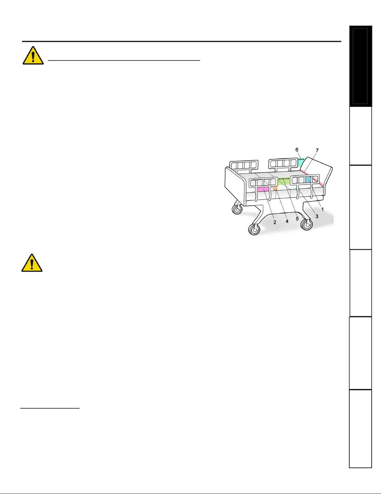
entrapment and published safety guidelines for hospital beds. The FDA has identified seven zones
in the hospital bed system where there is a potential for patient entrapment. Entrapment may occur
in flat or articulated bed positions, with the rails fully raised or in intermediate positions. The seven
entrapment zones are identified in the drawing below.
ENTRAPMENT ZONES:
Zone 1: Within the Rail
Zone 2: Between the Top of the Compressed Mattress and the
Bottom of the Rail, Between the Rail Supports
Zone 3: Between the Rail and the Mattress
Zone 4: Between the Top of the Compressed Mattress and the
bottom of the Rail, at the End of the Rail
Zone 5: Between the Split Bed Rails
Zone 6: Between the End of the Rail and the Side Edge of the Head
or Foot Board
Zone 7: Between the Head or Foot Board and the Mattress End
MC Healthcare is a member of the FDA's Hospital Bed Safety Workgroup. All beds purchased from MC
Healthcare with mattress, side rails and accessories as a complete system meet the federal entrapment
guidelines at the time of shipping. MC Healthcare is available to work with customers to minimize the
risk of patient entrapment.
COMPLIANCE - Entrapment Safety
DISCLAIMER
The M. C. Rexx - series low beds are intended to be used for resting and sleeping in a long
term care environment. The beds are not to be used as a tool for diagnosis (determining cause of
an illness), treatment (action(s) taken to change the course of an illness) or monitoring (reading
and/or recording physiological parameters).

6
PRODUCT FEATURES AND SPECIFICATIONS
The M. C. Rexx series bed is designed for a safe working load of 450 pounds (226kg). Body weight
should be evenly distributed over the surface of the bed. Do Not lay, sit or lean in such a way that the entire
body weight is placed only on a raised head or foot section of the bed.
Customer Support
Maintenance
Operating Instructions
Troubleshooting
Safety Instructions
Assembly
M. C. Rexx Bed Specification
Height Floor to Mattress Support 7 7/8 – 26" Travel range and 7 7/8 – 28" on Fast bed.
Deck Angles 1. Head elevation 0 - 70 degrees with horizontal.
2. Knee elevation 0 - 20 degrees with horizontal.
Adult Bed Length 1. Overall length 85 1/4" inches with Boards (add 3 1/4" for wall bumpers).
2. Sleep surface 80 inches.
Youth Bed Length 1. Overall length 81 1/4" inches with Boards (add 3 1/4" for wall bumper).
2. Sleep surface 76 inches.
Bed Width Overall width (with side rails) 40 1/2" inches.
Mattress Deck 1. Width 35 inches.
2. Length 76 or 80 inches.
Mattress Support Deck Construction Welded steel angle frame and rod.
Mattress Stops Steel Corner and Side Stops.
Bed End Panels Permanent or removable mounting.
Electrical Safety Certification Certified to:
CAN/CSA STD C22.22 No. 601.1-M90
UL Std No. 60601-1 (2003)
Mechanical Safety Certification Conforms to:
IEC 60601-2-38 Clause 28.4(2)
Classification Class I, Type B.
Voltage/Hertz/Phase
Maximum Input Current Rating
120/60/1.
3.5 Amp (120V).
Cord Type / Length 2 .5 Meters minimum, 3 prong hospital grade plug.
Electric Motors Three (3) DC self lubricating Linear Actuators.
Operation 10% Maximum Duty Cycle (2 minutes on/18 minutes off)
Emergency Power back-up battery Pack. 24 V DC Wall Mounted Battery with Charger.
Protection against splashing water IPX4.
Mass of bed 170 lbs without any accessories.
Safe Working Load
200 Kg = 450 Lbs (includes the Patient, Head/foot Panels,
Mattress Side Rails and accessories).
Mobility At any height (7 7/8 - 26") or (7 7/8 - 28").
Swivel Casters Heavy duty 3”– total locking casters.
7
Customer Support
Maintenance
Operating Instructions
Troubleshooting
Safety Instructions
Assembly
PRODUCT FEATURES AND SPECIFICATIONS- continued
Environment conditions
OPERATING Temperature
Relative Humidity
Atmospheric Pressure
STORAGE Temperature
Relative Humidity
Atmospheric Pressure
10 º C to 40 º C
30 % to 75 %
700 to 1060 hPa
-10 º C to +50 º C
20 % to 90 % @ 30 º C - not condensing
700 to 1060 hPa
Motor Function Controls Six (6) function pendant.
1. Hi/Low Elevation Up and Down keys.
2. Head Deck Up and Down keys.
3. Knee Deck Up and Down keys.
Foot End (Staff) Controller
1. Hi/Low Elevation
2. Head Deck
3. Knee Deck
Optional - Factory or Field Installed.
Individual Lock and Unlock control over all functions. FEC
remembers setting before power outage or removal of
foot-board.
Vascular Foot Deck Ratchets Manual elevation to help aid for cases of edema.
Head End Wall Stand-Off Bumpers. Impact absorption bumpers.
3/4 Length Collapsible Side Rail Model #
RR501
Optional - Field Installed.
Fits 76" and 80" Sleeping Surface Decks.
Head End Assist Rail Model # RAD306 Optional - Fits 76" and 80" Sleeping Surface Decks.
Three Position Assist Rail Model # RM930 Optional - Fits 76" and 80" Sleeping Surface Decks.
Frame Mounted Assist Rail # RM950 Optional - Fits 76" and 80" Sleeping Surface Decks.
I.V. Ports Optional.
Trapeze- patient helper bracket and a
patient helper bar.
Optional.
Bed Extender, Board Extender and Rail
Extenders.
Optional - 6" Foot or Head End.
Mattress Proper sized mattress with special firm borders to
prevent patients from being trapped between the
mattress and rail. Contact your M.C. Healthcare Products
Representative for mattress sizing recommendations.
MANUFACTURER DISCLAIMER Specifications are subject to change without notice, MC Healthcare reserves the right to
continuously improve its products. Illustrations are intended to represent the product and may vary from actual production
models.
200 Kg = 450 lbs.
=

8
Your M. C. Rexx Bed is equipped with three motors to operate each of three functions:
Bed up/down Adjusts the height of the bed from 7-7/8” to 26” or 28".
Head up/down Adjusts the angle of the head deck from 0° to 70°.
Knee up/down Adjusts the angle of the knee deck from 0° to 20°.
This instruction manual covers options and accessories which may not be included on your bed.
Before operating your M. C. Rexx Bed, be sure that you have completely read and understood the
instructions and warnings contained in this manual and included with the accessories.
Unpacking Instructions - (PLEASE RECYCLE)
Your M. C. Rexx bed is shipped in a vertical position with the Head-End on the ground. If it has not been
lowered flat, then two people are required to lower it gently to the ground.
Cut the "shipping ties" securing the deck to the frame. There are also ties securing wiring in place, care must be
taken so that only the "shipping ties" are removed. The "shipping ties" can be identified by the fact that they
have not been trimmed.
Remove one package attached to the frame containing the Mattress Stops, the Roller Bumpers and the Board
Mounting Brackets. Make sure that all parts are included prior to disposing of the packaging material and
immediately report any missing parts to MC Healthcare Customer Service.
Mattress
The M. C. Rexx bed has been designed to minimize the risk of patient entrapment while
maintaining as much patient comfort and protection as possible. All mattresses supplied by M.C.
Healthcare Products work together with the siderails to meet the FDA guidelines at the time of
purchase. If other mattresses are used, it is up to the end user to determine whether their mattress is
suitable for minimizing entrapment risks.
In any case only hospital grade mattresses with firm borders, a minimum of 6" thick by 35" wide by
80" long (76" for a 76" deck) should be used. It is also up to the end user to periodically check the
mattresses to ensure that they maintain their dimensions over time.
Contact your local M.C. Healthcare Products Representative for mattress recommendations.
Customer Support
Maintenance
Operating Instructions
Troubleshooting
Safety Instructions
Assembly
ASSEMBLY INSTRUCTIONS
1
2
3
www.mchealthcare.com
Introduction
WARNING! POSSIBLE INJURY OR DEATH
improper routing of the power cord
could result in injury or death. Ensure that you do not remove any Cable ties that are intended to
keep the power cord away from moving parts.
Power Supply Cord
To keep the power supply cord off the floor when
moving or storing the bed, you need to secure the
cord using the VelcroRStrap as shown.
Secu
re
Cor
d with
the
Ve
lc
ro
Str
ap

9
Customer Support
Maintenance
Operating Instructions
Troubleshooting
Safety Instructions
Assembly
ASSEMBLY INSTRUCTIONS - continued
The optional patient helper consists of a bracket mounted to the frame, and an
arm with an adjustable handle. The arm can be located in three positions by use
of a locking spring pin. There is a side position for assistance entering and exiting
the bed (A), an in-bed position for assistance with repositioning (B), and a storage
position (C). The chain is attached using a “quick link” that allows the height and
position of the handle to be easily adjusted. You must follow the instructions
provided with the Helper.
WARNING!
Ensure that the spring loaded Pull Pin is properly engaged to prevent the Patient
Helper Pole from rotating. Failure to do so could result in serious injury.
Patient Helper - optional
A
PULL PIN
B
C
Bed Extender - optional
The bed extender is designed to be attached at the foot or at the head end of
the bed. The extender attaches directly to the foot or the head deck. If a foot
or head board is to be used with the extender, then a set of board extender
brackets are required to offset the foot or head board, and allow clearance for
the extender. The mattress pad extends the actual sleep surface.
To meet FDA Entrapment Guidelines a Side Rail Extender must be used on
beds equipped with 1/2 Length Side-Rails.
WARNING! POSSIBLE INJURY OR DEATH
Use only the proper size mattress and
extension pads in order to minimize the Entrapment Zone gaps. The gaps must be small enough to
prevent the patient from getting his/her neck caught in this location (you must read and follow the
FDA Entrapment Guidelines).
Mattress Stops Installation
Tools Required: 5/16 and 3/8” wrenches.
Parts Included:
Item # Qty Part Number Description
1 4 QS3484 CORNER MATTRESS STOP
2 8 QP2501 MACHINE SCREW #10-32 X 5/8” HEX HEAD ZP
3 8 QP2502 NUT 10-32 HEX NYLOCK ZP
1- Raise the bed to make the installation easier.
2- Place one Mattress Stop (1) in one corner overlapping the pre-punched holes; as illustrated.
3- Place one Screw (2) through one of the holes and thread a Nut (3) onto the screw behind the deck frame.
Tighten Nut finger tight . Repeat for the other hole.
4- Tighten the screws with a 5/16" Wrench while using a 3/8”Wrench to prevent the nut from spinning.
5- Repeat for the other 3 corners of the bed.
6- Tighten all screws.
Procedure:
2
3
1
10
Customer Support
Maintenance
Operating Instructions
Troubleshooting
Safety Instructions
Assembly
ASSEMBLY INSTRUCTIONS - continued
www.mchealthcare.com
Bed Installation
The M. C. Rexx bed is approved for
operation in a dry environment. To operate
the bed, plug the Power Cord running from
the patient left hand side of the frame into
a three prong 110 V hospital grade wall
receptacle. The Hand Pendant is already
plugged into the controller and the bed
should now be operational.
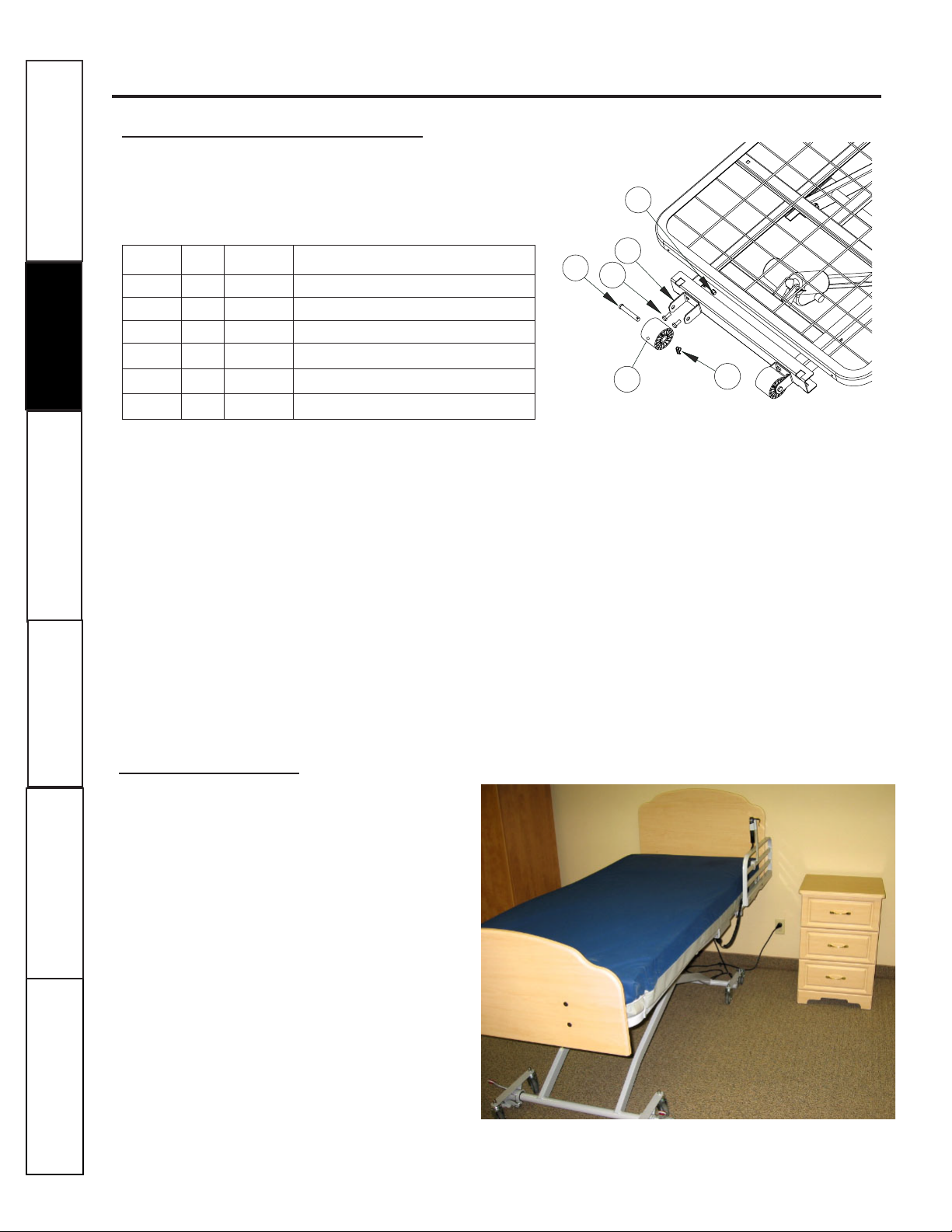
Roller Bumper Installation
Tools Required:
Ratchet wrench with ½” socket- ½” wrench
Parts (included):
Item # Qty Part # Description
1 4 1850 BOLT HEX 5/16-18 X 3/4"
2 2 QP-1550 CLEVIS PIN 7/16 X 2-3/4"
3 2 QP-2041 URETHANE ROLLER
4 2 QS-3560 ROLLER BUMPER BRACKET
5 2 QP-1748 COTTER RING RUE 1/2"
6 4 1854 LOCKNUT 5/16 - 18
Procedure:
Step 1 - Mount Roller bracket (4) on the head end of the bed frame as shown, using two hex head
bolts (1) and lock nuts (6). Repeat for other side.
Step 2 - Hold roller (3) inside the opening of the bracket, and insert clevis pin (2) through both of
the holes in the bracket and the center of the roller to hold it in place.
Step 3 - Insert the cotter ring (5) in the small hole in the end of the clevis pin.
Step 4 - Repeat for the opposite side.
4
2
35
1
6

11
Customer Support
Maintenance
Operating Instructions
Troubleshooting
Safety Instructions
Assembly
Head and Foot Board Mounting Bracket Installation
Tools Required: two 5/32" Hex-Allen-Keys.
Parts (included):
Item # Qty Part # Description
1 4 QP-2432 Board Mounting Bracket
2 8 QP-2431 NUT JCN 1/4-20- 17mm Long
3 8 QP-2433 Screw 1/4-20 x 5/8 Flat Head Hex Drive Zn
Procedure:
HEAD BOARD
Install two Board Mounting Brackets (1) with four Screws
(3) and four Nuts (2) as illustrated. Do not tighten until after
inserting the mounting brackets in the bed frame posts- (see
next page).
FOOT BOARD
Install two Board Mounting Brackets (1) with four Screws (3) and
four Nuts (2) as illustrated. Do not tighten until after inserting the
mounting brackets in the bed frame posts - (see next page).
1
23
HEAD BOARD
23
1
FOOT BOARD
ASSEMBLY INSTRUCTIONS - continued
Bed Components
EMERGENCY BATTERY
EXTENSION CORD SOCKET
BACK-UP PORT
24V BATTERY
HEAD MOTOR
TOTAL FLOOR
LOCK
FOOT MOTOR
CONTROL BOX
END
OF BED
HEAD
POWER CORD
FOOT END CONTROLLER
(FEC) PLUGS
STRAIN RELIEF
POWER CORD
HAND PENDANT
Hi-Lo MOTOR

Customer Support
Maintenance
Operating Instructions
Troubleshooting
Safety Instructions
12
Assembly
ASSEMBLY INSTRUCTIONS - continued
Insert the Head and Foot Boards as illustrated with the proper
Mounting Bracket orientation.
After the Boards are in place, tighten the eight Screws and JCN
Nuts that were left untightened from the previous step.
Attach a # 6 Screw and Nut through each hole in the bottom of
the Foot Board Mounting Brackets to prevent the Foot Board
from being removed accidentally.
Secure the Head Board to the bed frame by installing a Lynch
Pin through the hole in the bottom of each Head Board
Mounting Bracket to prevent the Head Board from being
accidentally removed.
1
2
Head and Foot Board Installation
www.mchealthcare.com
WARNING!
Entrapment Safety:
Use only the proper
size boards and mattress to minimize the Entrapment
Zone gaps. The gaps must be small enough to prevent the
patient from getting his/her neck caught in this location
(you must read the FDA Entrapment Guidelines ).
The entrapment zones are a resultant of the dimensional
interaction between the bed and components that are
often assembled by the Healthcare Facility and not the
Manufacturer.
The Healthcare Facility is responsible for compliance
with the Entrapment Guidelines by matching the right
components and accessories to the right bed.
3
WARNING!
To prevent fingers from getting caught
between the sleeping surface and the foot and head ends of
the bed, the Head and Foot Boards should remain attached
to the bed frame at all times.
4
HEAD BOARD
FOOT BOARD
FOOT BOARD

Maintenance
Operating Instructions
Safety Instructions
Assembly
Maintenance
Operating Instructions
Troubleshooting
Safety Instructions
Assembly
OPERATING INSTRUCTIONS
WARNING!
The siderails should always be in the up position when the patient is left
unattended. Test the siderails to ensure that they are properly latched before leaving the patient.
WARNING!
Always evaluate patients for and guard against patient risk of side rail entrapment
in accordance with medical protocols. Failure to do so could result in injury and/or death.
WARNING!
The siderail pads must be removed prior to operating siderails. Failure to do so
could result in injury.
Customer
Support
Siderails -
All Siderails are optional.
¾ Length Siderails
Lifting the siderail up completely will latch it into the upright position.
To lower the rail, you must pull the large knob which is located at the
foot end of the siderail before lowering. The ¾ rail swings towards the
head of the bed.
Three Position Pivoting Assist Rail
The optional Pivot Assist will latch in three upright
positions. To rotate the Pivot Assist you must press
the release button located at the base of the rail
- you must follow the instructions included with
the rail.
WARNING!
Test the Assist Rail to ensure that it is properly latched before leaving the patient.
WARNING!
To prevent fingers from getting caught
between the rails:
Fixed Assist Rail
The optional Assist Rail fits on the left or the right
hand of bed - you must follow the instructions
included with the rail.
Pull the large knob to lower the side rail to its first position.
Keeping fingers clear from between the rails, pull the small knob to
take the rail to its lowest position. Failure to do so could result in injury.
1.
2.
Safe Hand Position
LARGE KNOB
13
1
2
3
Three Position
Assist Rail
Assist Rail
14
OPERATING INSTRUCTIONS
Customer Support
Maintenance
Operating Instructions
Troubleshooting
Safety Instructions
Assembly
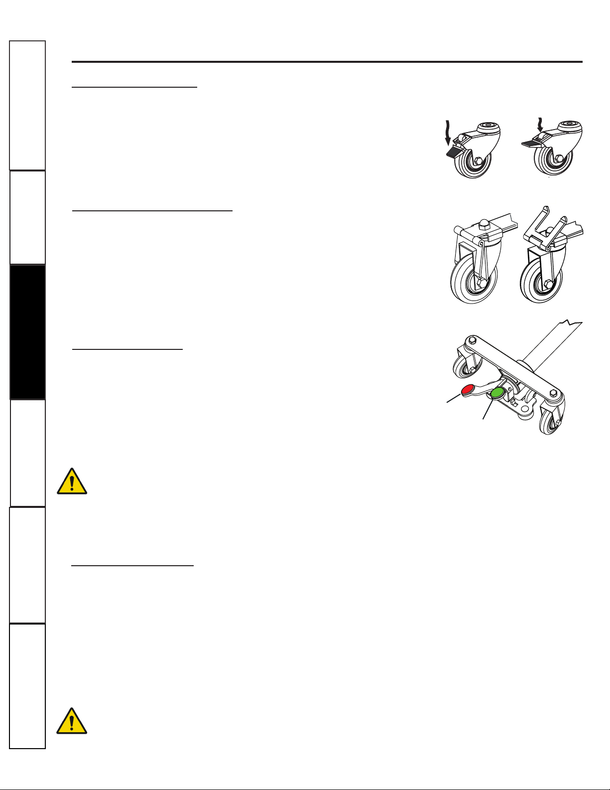
To engage the total lock casters, simply press down on the locking tab with
your toe on all four casters. This will prevent any movement of the caster
(rolling or swiveling). The rubber wheel gives good traction on most floor
surfaces.
To release the casters and allow mobility of the bed, press down on the
release lever to unlock each caster.
Total Lock Casters
LOCKED CASTER UNLOCKED CASTER
WARNING!
When the bed is not being moved, the casters should always be locked. After
applying the brakes test the motion of the bed to ensure that the brakes are properly engaged.
Patients tend to use the bed for support when getting in or out of bed, and could be injured if the
bed unexpectedly moves sideways.
www.mchealthcare.com
Transporting Bed
The M. C. Rexx bed is designed for mobility at any height. Use the Foot Board to move the bed. Never use
Side Rails, Assist Rails or other accessories to move the bed.
To prevent any damage or injury, it is recommended that two Personnel be present when moving a bed.
1 The Power Cord is unplugged and the cord is safely stored off the floor .
2 All the head and foot brakes are released.
3 All accessories used on the bed are secured or removed.
Before moving the bed you should check all around the perimeter of the bed to ensure that no accessories will fall or
get damaged and that:
WARNING!
Do not roll the bed over high thresholds with the patient in the bed.
Directional Lock Hinge
Patients tend to use the bed for support when getting in or out of bed.
Patients could be injured if the bed moves sideways, to guard against
this risk you must engage the "Directional Lock Hinges". Simply flip the
U-shaped tab down with your toe over both casters. This will prevent
any lateral movement (swiveling) of the caster. To release the casters and
allow full mobility of the bed, gently flip the U-shaped tab over the square
leg tube for each caster.
The Total Floor Lock is engaged by simply stepping with the ball of your
foot on the Red end of the Pedal located on the Foot and/or Head ends
of bed - as illustrated. This will immobilize the Foot and/or Head ends of
the bed.
To make the bed mobile again, unlock the Total Floor Lock by stepping
on the green end of the Pedal.
Total Floor Lock
LOCKED
UNLOCKED
RED
LOCKED POSITION
GREEN
15
Customer
Support
Maintenance
Operating Instructions
Troubleshooting
Safety Instructions
Assembly
OPERATING INSTRUCTIONS
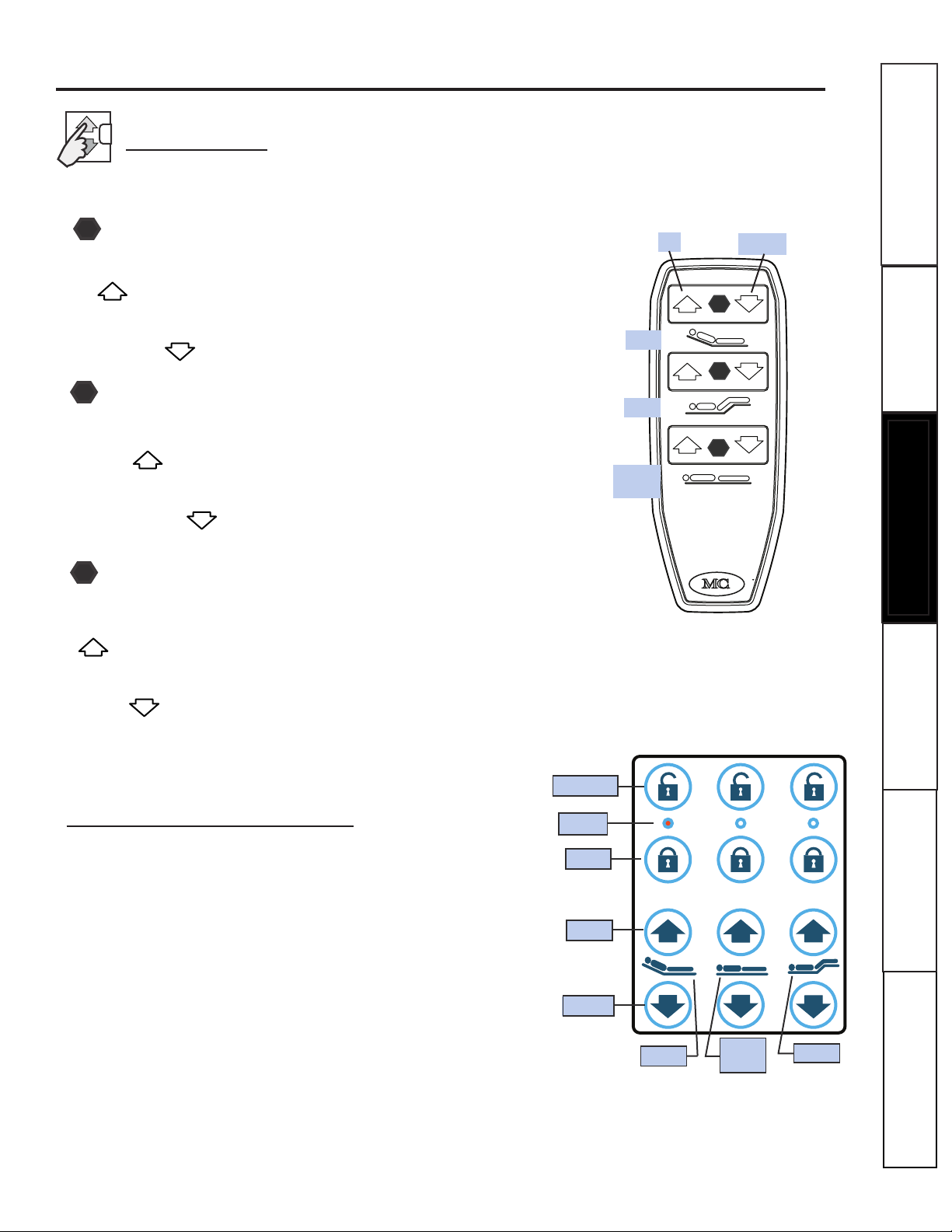
Bed Controls
The M. C. Rexx Bed is electrically operated using Hand Pendant Controls as follows:
To gently raise the patient's Head, press and hold the top Head
UP button on the pendant.
To gently lower the patients Head, press and hold the top
Head DOWN button on the pendant.
Head Deck Operation
1
Knee Deck Operation
2
To gently raise the patient's Knees and Feet, press and hold the
Foot UP button on the pendant.
To gently lower the patient's Knees and Feet, press and hold
the Foot DOWN button on the pendant.
Bed Deck Hi/Lo Elevation
3
To gently raise the Bed, press and hold the bottom Bed UP
button on the pendant.
To gently lower the Bed, press and hold the bottom Bed
DOWN button on the pendant.
1
UP
DOWN
HEAD
2
KNEE
BED
Hi/Lo
3
The FEC (Staff) Controller mounts flush on the Foot-Board
and allows the caregiver to operate the bed or to lockout the
bed functions so that they cannot be operated with the hand
pendant. The FEC remembers the last setting before the foot-
board is removed or before an electrical power outage.
Foot End (Staff) Controller
- The LED light turns ON to indicate a LOCKED function.
- The LED Light flickers when a bed function is being operated.
NOTES:
BED
Hi/Lo
HEAD KNEE
LED
LOCK
UNLOCK
UP
DOWN
Customer Support
Maintenance
Operating Instructions
Troubleshooting
Safety Instructions
Assembly
16
OPERATING INSTRUCTIONS
www.mchealthcare.com
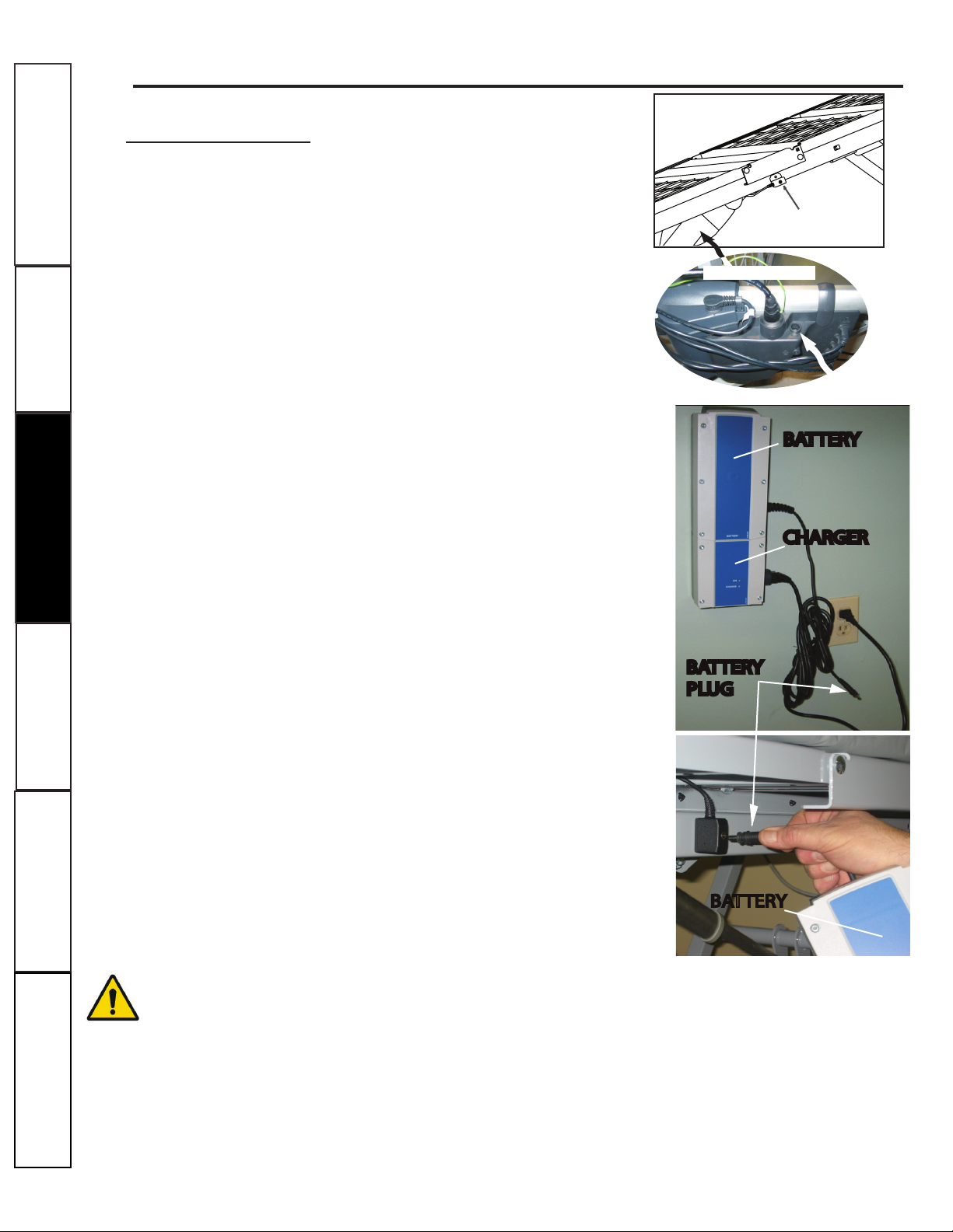
The Back-up Battery Model # Q6598L is for use when there is a
power outage, or the bed needs to be operated where there is no
power source nearby.
A fully charged battery may operate up to 30 beds on one charge.
An optional Back-up Battery Extension Cord is available that allows
easy access to the battery port on the Controller. The Extension
Cord Socket is mounted under the seat deck on the side of the bed.
Plug the Charger into a 110 V socket and insert the Battery in
the Charger - keep the battery charger plugged in when not in
use to maintain a full charge.
Back-up Battery Usage
*To use the Back-Up Battery, remove the battery from the char-
ger, and take it to the bed(s).
*If there is a Battery Extension Cord on the side of the bed, plug
the battery plug into the Socket, and operate the bed nor-
mally.
*If there is no Extension Cord, connect the battery plug into the
Back-up Battery Port on the side of the Controller box, and use
the bed normally.
*When complete, return the Back-up Battery to it’s original
location, and insert it back in the charger.
IMPORTANT!
Depending on the location of the beds within the Healthcare Facility, it is
recommended that at least one Battery-Pack is needed for 1-5 beds with an additional Battery-Pack
for each additional 5 beds. Depending on the layout of the Healthcare Facility more or less Battery-
Packs might be needed. The Healthcare Facility is responsible for matching the number of Batteries
to the number of beds in compliance with Medical Protocols, Agency and Regulatory guidelines.
Back-up Battery
CHARGER
BATTERY
BATTERY
PLUG
BATTERY
Battery Extension Cord
Socket under Seat Deck
24V DC BACK-UP
BATTERY PORT
CONTROL BOX
17
Customer Support
Maintenance
Operating Instructions
Troubleshooting
Safety Instructions
Assembly
MAINTENANCE
WARNING!
The Actuator must be used and maintained
correctly and not exposed to violent treatment or tampered
with. If any irregularities are observed, the Actuator must be
replaced immediately.
Cleaning
The M.C. Rexx bed can be cleaned with warm water and a mild detergent or diluted disinfectant.
Use a damp cloth or a sponge to clean all exposed surfaces of the bed. Take care not to use excessive
water around the control panels and the control box.
WARNING!
The M.C. Rexx bed was not designed to be cleaned using a high
pressure wash tunnel. Never spray directly on to the actuator with a high pressure cleaner.
Preventative Maintenance
There are a number of maintenance items that should be reviewed every 6 months to ensure proper functioning
of the bed.
LUBRICATION
– All pivot and rotating joints should be lightly oiled with a penetrating lubricant containing
an extreme pressure additive (e.g. Castle Iron Man). A lithium based grease is not a suitable alternative for this
application. No lubrication is required on the motor itself, but the clevis pins may be lubricated if required.
Remove any excess oil/grease after application with a cloth.
MOTOR OPERATION– The motors should run smoothly and quietly throughout their range.
Normal operation over full range - The bed should move evenly through its full range of motion from low to high
position and from flat to contoured with no jerking or twisting.
GRINDING, POPPING, OTHER NOISES – The bed should be fairly silent. Some motor/gear noise is
normal and some settling noises are expected, but nothing loud and no squeaking. Look for abnormal wear,
lubricate any joints exhibiting noise.
ACTUATOR SYSTEM - The Actuator must be maintained correctly and not tampered with.
1- The Actuator must be cleaned at regular intervals to remove dust and dirt and inspected for
mechanical damages or wear.
2- Inspect all attachment points, wires, piston rod, cabinet, and plug as well as check that the
actuator functions correctly.
3- The actuator is a closed unit and requires no internal maintenance.
4- To ensure that the pregreased inner tube remains lubricated the actuator must only be washed
down when the piston rod is fully retracted.
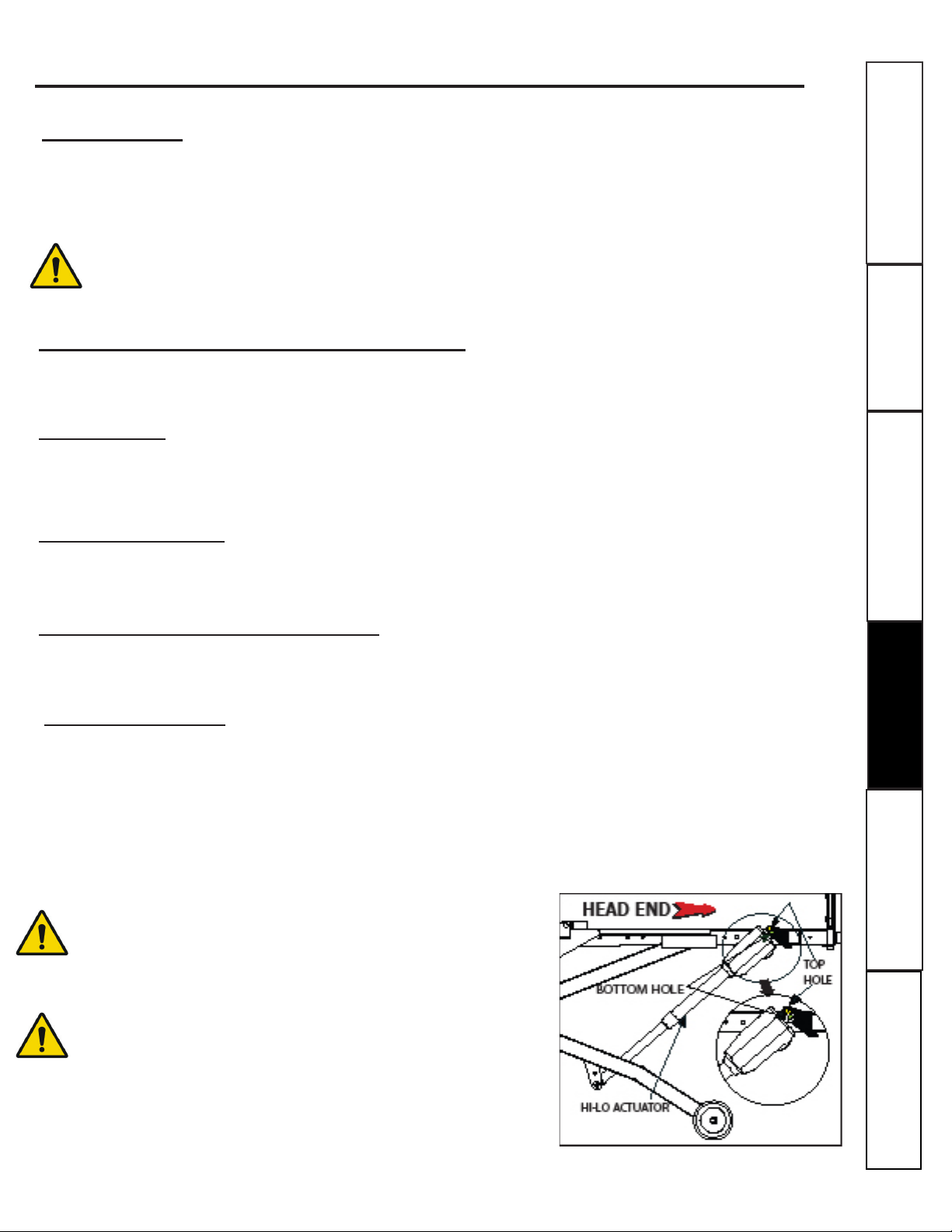
IMPORTANT! PROPER INSTALLATION OF
ACTUATOR
When replacing the Hi-Lo Actuator on this bed
you must ensure that the Actuator orientation is correct and
that the actuator is installed using the bottom hole for QD2250
or top hole for QD2000 on the clevis plates located on the head
end of bed frame. Failure to do so might result in property
damage or injury.

Customer Support
Maintenance
Operating Instructions
Troubleshooting
Safety Instructions
18
Assembly
MAINTENANCE
www.mchealthcare.com
FASTENERS – Ensure that all fasteners are tightened and seated completely. Do not over-tighten the
fasteners at the pivot points of the Decks.
CABLING Inspect the cabling on the bed to ensure that it is all still in place with no drooping or loose
wires, and that it is not interfering with any moving parts. Check for any cut, nicked or crushed wiring.
Reattach any loose wires, and repair or replace any damaged wires.
POWER CORD – Inspect the power cord for nicks or crushed insulation. Replace if damaged with original
manufacturer parts only.
CASTER LOCKING – Check to ensure that the casters swivel and roll freely when unlocked, and do not
swivel or roll when the lock is engaged. Tighten, repair or replace if damaged, loose or not working properly.
Note: a torque of 25-30 lb-ft (300-360 in-lb) should be applied on the 3/8" Caster.
SIDERAILS – Check the action of the siderails. The rails should move freely through their range, latch fully
when raised, and not be excessively “wobbly” when raised.
HEAD & FOOTBOARD PANELS – Inspect the wood panels for nicks, scratches and missing edging. Seal any
damage that penetrates through to the wood to prevent possible water damage.
PAINT FINISH – Check the bed for any loose, missing, peeled, scraped off or flaked paint. Touch up as
required.
OVERALL APPEARANCE – Inspect the bed generally. Visually inspect welds on the bed and accessories
and look at any bent or cracked components. Document any concern and remove the bed from service
immediately until the affected parts are replaced or the corrective action is taken.
WARNING!
Damage to the cotter pins may occur when the bed is in its lowest position
and removing patients using a patient lift and/or cleaning areas under the bed.
NOTE: The low end of the Hi-Lo Actuator must have an "Extended Prong Style Cotter Pin". The "Rue"
type pin is used on all other Clevis Pins.
RETAINING RINGS – All clevis pins must have retaining rings present. Replace any missing rings. All
"Rue" type pins should be manually locked and visually inspected on a regular basis, as illustrated below.

19
Customer Support
Maintenance
Operating Instructions
Troubleshooting
Safety Instructions
Assembly
MAINTENANCE
Preventative Maintenance Inspection Chart
The bed must be inspected at least once a year by qualified technicians.
This chart is included to document these inspections and will help support any future warranty
claims if required.
Parts that are found to be worn or defective should be replaced with new parts from MC
Healthcare. To identify replacement and spare parts please refer to the exploded parts diagrams in
the Service Manual of the bed.
DATE
POWER CORD- NO
FRAYING OR CUTS
BUSHINGS
ACTUATOR
MOTOR OPERATION
NORMAL OPERATION
OVER FULL RANGE
GRINDING POPPING
AND OTHER NOISES
BENT PARTS
CLEVIS PINS AND
FASTENERS
RETAINING RINGS
CABLING NO VISIBLE
WEAR
CASTER LOCKING
SIDE RAIL & LATCHES
HEAD AND FOOT
BOARD PANELS
INSPECT
ALL AROUND
CLEAN DIRT AND
IMPURITIES
PAINT FINISH
INSPECTOR'S
INITIALS
COMMENTS

20
If you are having a problem with your M. C. Rexx bed, please go through this troubleshooting section
to see if your problem can be resolved easily. If you are still having problems, then please call our Parts
and Service Department for assistance at 1-800-268-8671. Do not ship any parts back to M.C. Healthcare
Products without an RMA (Return Material Authorization) number, they will not be accepted, and no credit
will be given.
Customer Support
Maintenance
Operating Instructions
Troubleshooting
Safety Instructions
Assembly
When some, but not all functions work on a bed, it typically indicates that there is a problem with the hand
pendant or one of the motors, but not the Controller.
TROUBLESHOOTING TIPS
PORTS
1 – Foot Motor (Yellow) 2 – Head Motor (Blue)
3 – Hi/Lo Motor (Red) 4 – Spare not used (Red)
H –Hand Pendant (Green)
1
If a nurse lock-out box or Foot End
(Staff) Controller is present, ensure that
it is unlocked. If it is not, then turn the
function switch to the unlock position,
and the function should now work. If this
is not the case, continue with the next
step.
2
Ensure that all of the connectors are firmly
seated, and then check to see if this corrects
the problem.
5
4
3
Try using a different handset, either from
another bed, or a spare. If this resolves the
problem then a replacement handset is
needed.
If the problem persists, try switching the
motor ports. Select a motor that is working,
and plug it into the port that is not working.
If the function works (it may work in
reverse) then the problem is with the motor.
Plug the motor that was not working into a
working port and try it. If the motor works
in this port, then the problem is with the
controller.
Before you call for Service (Always record the Serial Number of the bed)
www.mchealthcare.com
PRoBleM: one MotoR function not woRking
HI-LO MOTOR
24V DCBACKUP
CONTROLLER
120V AC POWER
1
H432
FOOTDECK
MOTOR
BATTERY
HAND PENDANT
GREEN LED
LOCK-OUT BOX OR
FEC CONTROLLER
FEC CABLES
HEADDECK
MOTOR
SPARE
This manual suits for next models
1
Table of contents
Other MPS Medical Equipment manuals


