ST&G 1324 AP User manual

Instructions for 1324 AP / AL
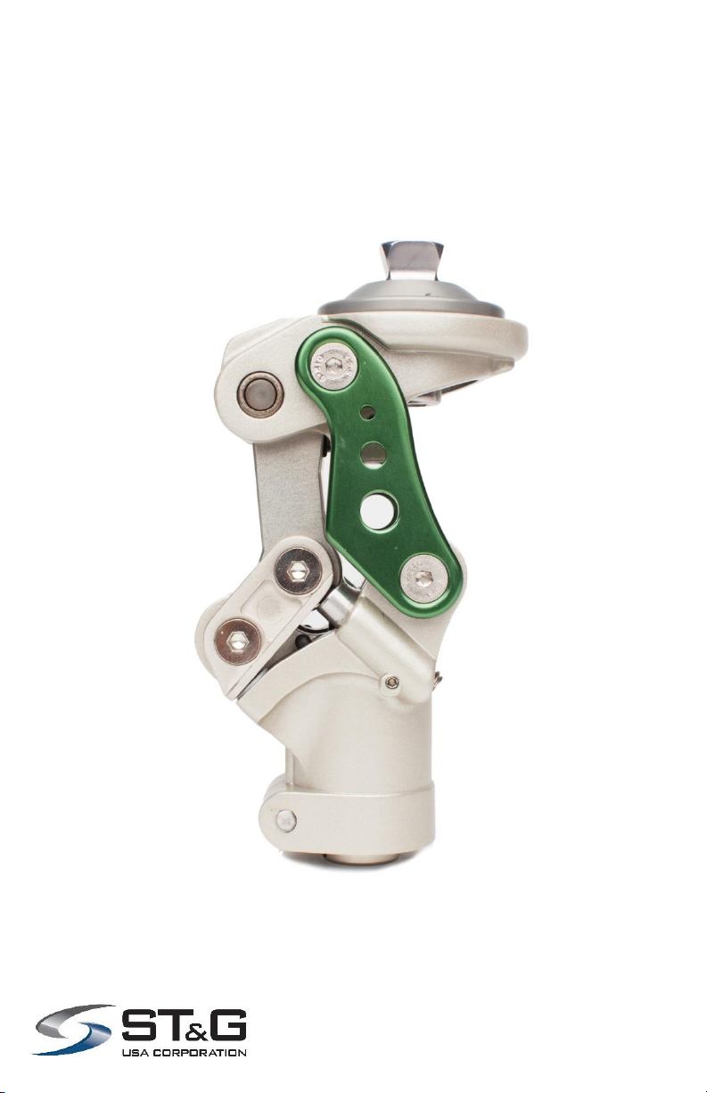
Stance Flexion 5 Bar
Mechanical Knee
ST&G USA Corp. Phone: (714) 524-0663
2691 Saturn St. Fax: (714) 364-8113
Brea, CA 92821 www.stngco.com

1 Description and purpose
These instructions are for use by the practitioner.
The 1324 AP/AL knee is to be used exclusively as part of a
lower limb prosthesis
Recommended for amputees with K2 activity level
Weight limit for a user is up to 125 kg / 275 lbs
Contra-indications
Residual muscular weakness, contractures or proprioceptive dysfunction
including poor balance.
Contra lateral joint instabilities or pathology
Complicated conditions involving multiple disabilities
Product Code
1324 AP / AL
Polycentric Mechanical Knee Unit (Aluminum) with Stance Flexion Control
125Kg
275lbs
Ensure the end user has understood any Instructions for use, especially to
the safety information.

2. Construction
Principal Parts
Frame Aluminum Alloy, Brass, Stainless Steel, Steel
Knee head Aluminum Alloy, Stainless Steel
Knee control Various materials principally Aluminum Alloy, Stainless Steel,
Poly Urethane Copper
1) The First Axis
2) The Second Axis
3) The Third Axis
4) The Fifth Axis
5) The Fourth Axis
6) Knee Head
7) Side Bars
8) Back Linkage
9) Fifth Axial Bars
10) Knee Body
11) Knee Head Level Adjusting Screw
12) Flexion Control Adjusting Screw
13) Lock Screw for Extension Assist Adjusting Screw
14) Extension Assist Adjusting Screw
15) Tube Clamp Screw
16) Friction Swing Resistance Adjustment Screw

The Caution symbol highlights safety information which must be followed carefully.
Be aware of finger trap hazard at all times
Any changes in performance of the knee e.g. instability or lag in transition
from full stance flexion moment to full knee extension moment in the knee
should be immediately reported to the Clinician / Practitioner
Any excessive changes in heel height may adversely affect the stability of
the knee.
The user should be advised to contact their Clinician / Practitioner if their
condition changes.
4 Safety Information
Important:
DO NOT adjust out stance flexion to 0°- must maintain
minimum of 5°stance flexion up to 12°, 0°stance flexion
can potentially lead to knee failure.
3 Function
The flexion control angle up to 12 degree for mimicking normal knee flexion
from heel strike to foot flat of a gait cycle
Pyramid and Knee Disarticulation mounting options
30mm Distal Tube Clamp
Adjustable spring extension assist
Adjustable knee head level angle
Adjustable friction
The most light weight in the present market
NOTE: Stance Flexion set screws have been eliminated. The
threaded holes remain, but will not contain a screw.

5 Maintenance
Maintenance must be carried out by qualified personnel.
Bi-Annual inspection is recommended.
Check for visual defects that may affect proper function.
A loaner system is available should servicing be required.
The wearer should be advised:
Any changes in performance of this device must be
reported to the Clinician / Practitioner.
Changes in performance may include:
Increase in knee stiffness
Knee instability
Any unusual noises
Cleaning:
Use a damp cloth and mild soap to clean the outside surfaces.
DO NOT use aggressive cleaning agents.
If the limb/knee comes into contact with salt or chlorinated water,
it should be rinsed with fresh water and dried.
6 Limitations on use
Intended Life:
Service life of the product is covered by the warranty period (2 years)
This product is recommended for use with other ST&G Products.
Lifting Loads:
Amputee weight and activity is governed by the stated limits.
Combined weight of amputee and carrying load, should not exceed stated weight limit.
Environment:
Avoid abrasive environments such as those containing sand for example
as these may promote premature wear. Avoid contact with talcum
powder.
Operating and Storage Temperature Range:
Exclusively for use between temperatures of -10˚C to 50˚C [14˚F and 122˚F]

7 Alignment and Set-Up
Users be aware of potential finger trap hazard
Note: 4-bar knees inherently are very stable due to the geometry built into each design. This
is commonly referred to as the Instant Knee Center (IKC). The IKC point when doing bench
alignment, will fall behind the traditional TKA line that we will reference. (Fig. 2,3) Tg line in
Fig. 3 is ideal placement, but in certain instances, it may be necessary to accommodate
placement anteriorly (into the T1 zone up to 2mm), or posteriorly (into the T2 zone up to
2mm). The Tg line is referencing a moving weight bearing line, so it could be in T1, neutral, or
in T2 zones.
BENCH ALIGNMENT:
a) With prosthesis assembled, taking into account hip flexion contractures, abduction, Line Of
Progression, and toe out (Fig.2), the TKA plumb line should pass through the knee center (at
the proximal/anterior pivot –red dot pivot Fig.3) and in front of the K point (IKC). Take into
account shoe heel height, and add 3mm safety factor.
Set the bench alignment taking into account the heel height of associated footwear plus 3mm
safety factor!
It is not recommended to have alignment posterior to the reference line, as it
could cause knee instability!
Add
3mm
safety
factor

b) Ideally, the pylon connecting the knee and foot should end up vertical. Of course,
there may be a variance due to the foot alignment recommendations. In this case, the
maximum
anterior tilt of the pylon should not to exceed 4 degrees, and it may be necessary to
utilize offset adapters like the 1222T off set tube clamp
c) The weight line should pass through the centerline of the knee in the Coronal or M/L
plane (Fig. 4). Excessive outset or inset will put undue stress on the knee joint.
d) The weight line for Sagittal or A/P plane should have the plumb line passing through T
(Tg) line. Ideally, Tg line should pass through the knee center (red colored pivot) and be
perpendicular to the ground. (Fig. 3)
e) When to use ZONE 1 option - For the higher weight spectrum patients, Tg line
should pass slightly into the “Zone I” area (up to 2mm), which is indicated as up to “T1”
(Fig. 3) so that it will reduce stance flexion moment forces of the 5th bar. It is
recommended to have controlled stance flexion action of the 5th bar, and not to lock it
out or have excessively long duration of it. Excessive stance flexion moment and/or
duration can be adjusted through tightening the “Flexion Control Adjusting Screw” in,
and/or adjusting alignment (of socket and/or foot) into the T1 zone (up to 2mm). The goal
is to have smooth transition from stance flexion to neutral mid-stance motion, and not
excessive stance flexion duration.
f) When to use ZONE 2 option - For the lighter weight spectrum patients, such as
women and children, Tg line should pass slightly into the “Zone II” area (up to 2mm),
which is indicated as up to “T2” (Fig.3) so that it will increase stance flexion moment
forces of the 5th bar linkage. It is recommended to have controlled stance flexion action
of the 5th bar, and not excessively short duration, or abrupt motion of it. Excessive short
stance flexion moment and/or duration can be adjusted through loosening the “Flexion
Control Adjusting Screw” out, and/or adjusting alignment (of socket and/or foot) into the
T2 zone (up to 2mm). The goal is to have smooth transition from stance flexion to neutral
mid-stance motion, and not abrupt motion or excessively short stance flexion duration.
CAUTION: Please pay extra caution on Tg line passing towards the maximum (up to 2mm) or
past Zone I because it will cause excessive knee head extension force, which will generate
excessive leverage pressure on "back linkage" and "fifth axial bar" and could result in knee
breakage as shown in Fig. 5.
It is highly recommended that Tg line should ONLY pass through the "Red Dot". (Fig. 3)
Fig. 5 An exaggerated
schematic diagram to show
affect on 5-bar linkage with
excessive anterior alignment

8 Knee Adjustment
8.1 Stance Flexion Adjustment
Important! adjustments to Stance
Flexion Bumper screws need to be
symmetrical! Apply thread locker to
screws one at a time to prevent screw
backing out.
Stance flexion adjustment screws are
located on the anterior body of the knee.
With 5mm hex wrench, turning both screws
clockwise decreases the 5th axis motion,
reducing the stance flexion angle. Anti-
clockwise will increase 5th axis motion,
increasing the stance flexion angle.
Adjustments need to be symmetrical!
8.3 Pyramid Head Position Adjusting
Loosen screw with 2.5mm hex
wrench.
Loosen Pyramid bolt with 8mm
hex wrench and rotate to
desired orientation and tighten.
Use 6mm hex wrench to turn screw clockwise
to increase extension assist, and anti-
clockwise to reduce extension assist.
8.2 Extension Assist Adjustment
Note: Loosen set screw prior to
adjusting.
Note: Tighten set screws after
adjusting.
Note: Mark/indicate pyramid orientation. Remove pyramid bolt and apply thread
locker, and torque bolt 18Nm. Tighten set screw to help prevent rotation.
NOTE: Stance Flexion set
screws have been eliminated.
The threaded holes remain, but
will not contain a screw.

8.6 Knee Friction Adjustment
Using a 3mm hex wrench, turn screw:
Clockwise to increase resistance.
Anti-Clockwise to reduce resistance.
Loosen the set screw prior to
adjusting. After adjusting, tighten set
screw.
Use 5mm driver and turn the screw
clockwise to reduce geometric stability of the
knee (high front/low rear) which makes knee
flexion initiation easier. Anti-clockwise will
increase geometric stability of the knee (low
front/high rear) which can make knee flexion
initiation more difficult.
Level or slight up-sloping tilt of 1-2 degrees (clockwise adjustment) is most
common. Anti-clockwise adjustment from factory setting will cause decrease in
bumper life span due to excessive compression forces.
8.4 Knee Head Tilting Adjusting
IMPORTANT! Head Tilt Feature is for fine tuning knee flexion initiation only!
It is not for increasing flexion or extension range for alignment. It is possible to
decrease knee stability by incorrectly adjusting this feature, which could lead to
your patient falling!

GAIT DEVIATIONS AND ADJUSTMENTS:
Excessive Heel Rise:
During walking, first try adjusting the knee friction adjustment by turning it up to
slow knee flexion initiation during swing. It might be necessary to very slightly
increase knee extension assist spring tension by 1/8 turn increments. Increasing
extension assist spring tension alone, will not reduce excessive heel rise
tendencies.
Alignment of this knee is influenced by weight line of socket, and
interaction of foot (stance flexion is reactive by these 2 factors). In most
cases, Stance Flexion might not be visibly noticeable, but the effect can be felt
by the wearer. 5 degrees of Stance Flexion will make a big difference. In some
cases, 12 degrees may be too excessive. Again, check your alignment with the
patient standing to see where the TA line falls versus the knee joint reference
point –the anterior proximal knee pivot.
Terminal Impact:
Terminal Impact can be reduced by increasing knee friction through the two knee
friction adjustment screws. Be sure to adjust both screws symmetrically. Also, it
may be necessary to reduce the extension assist spring tension. (Refer to
Section 8.3, 8.1)

9. Knee Maintenance
9.1 Changing Various bumpers:
For the knee head leveling bumper,
use 2mm hex wrench to loosen the
bumper set screw by turning anti-
clockwise.
Note: Indicate position of the screw prior
to removal. Push out the bumper by
turning the screw with 5mm hex wrench
clockwise.
Place new bumper back into the slot
same as previous one.
For the round shape bumper, use a
small standard screwdriver to pry out
the old bumper.
Insert with a new one.

9.2.2 Changing Stance Flexion Bumper
Use 4mm hex wrench to loosen the screws of fourth and fifth axes to take out the
side bars of stance flexion unit.
Please refer to the picture below
Pull out opposite side bar along with
fourth and fifth axes. Stance flexion
bumpers should be accessible for
servicing.

Key Dimensions:
9 Technical Specification
Operating & Storage Temperature Range: -10˚C to 50˚C ( 14˚F to 122˚F)
Weight (Pyramid/Lotus): 766g / 781g
Recommended Activity: K2
Maximum User Weight: 125kg (275lbs)
Maximum flexion angle: 135 degrees
Proximal Alignment attachment: Rotatable Male Pyramid/
Lotus Adapter
Distal Alignment attachment: Tube Clamp
Tube clamp torque setting: 12Nm
Pyramid Center Bolt: 18Nm
Build Height (Pyramid/Lotus): 112mm / 118.3mm
Materials: Aluminum Alloy, Stainless Steel, Steel, Rubber
Max. 135
Flexed
Build Height:
Pyramid = 112mm
Lotus = 118.3mm
14.5mm

CE Conformity
This product meets the requirements of 93/42/EEC guidelines for medical products.
This product has been classified as a class I product according to the classification
criteria outlined in appendix IX of the guidelines. Please keep this manual in safe place
for future use.
10 Warranty
Warranted for 2 years from the date of invoice by ST&G.
The user should be aware that changes or modifications not approved will void the
warranty.
11 Liability
The manufacturer recommends using the device only under the specified conditions
and for the intended purposes. The device must be maintained according to the
instructions for use supplied with the device. The manufacturer is not liable for
damage caused by the component combinations that were not authorized by the
manufacturer.

ST&G USA Corporation
www.stngco.com e-mail: info@stngco.com
2691 Saturn Street, Brea, CA 92821, USA
Tel: 1-714-524-0663 Fax: 1-714-364-8113
1324IFU Rev. B (01-19-18)
This manual suits for next models
1
Table of contents
Other ST&G Medical Equipment manuals
Popular Medical Equipment manuals by other brands

DMP Electronics
DMP Electronics XTLtouch Programming guide

Blatchford
Blatchford SmartIP Fitting instructions

Rotaid
Rotaid SOLID PLUS HEAT user guide

TensCare
TensCare Perfect mamaTENS Instructions for use

Belluscura
Belluscura X-PLOR Cartridge Replacement Instructions

Schrack Seconet
Schrack Seconet BT-IP user manual

Stryker
Stryker Power-PRO TL Cot Fastener Series Maintenance manual

NRS Healthcare
NRS Healthcare F20421 User instructions

Flaem
Flaem Lella the Ladybug P0406EM F700 Instructions for use

Cardinal Health
Cardinal Health CATALYST Patient Quick Reference Guide

Vermeiren
Vermeiren ILLICO Installation guides

PRALUENT
PRALUENT alirocumab Quick reference guide