Page 4 0901180 Rev: B (09/16)
INDICATION FOR USE
The Control Guard ACCS (Advanced Chemical Concentration System) is designed with ease of setup and use in
mind. By utilizing flow meter technology, the ACCS measures high concentrations of caustic, acid, rinse water or
other liquids with an extremely high degree of accuracy (+/- 2%) thereby ensuring precise chemical feed control. The
Control Guard offers multiple 4-20 mA analog inputs which provide the flexibility of being utilized by any “Off the
Shelf” probe whether it is pH, ORP, conductivity or other analytical measurements from a variety of popular
manufacturers (Rosemount, Sensorex, etc.). These features can be maximized by employing the Control Guard’s
distinctive data logging and reporting capabilities.
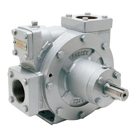
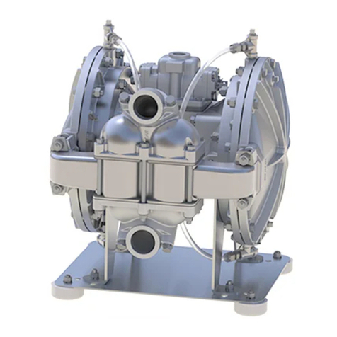
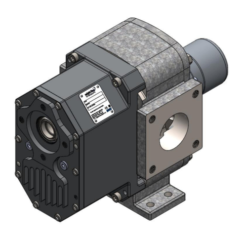
The Control Guard ACCS has the ability to operate up to 3 pumps of various designs including: Peristaltic, Air
Operated Diaphragm (AOD) and Electric Diaphragm Pumps (EDP). These can be employed in any of 4 modes of
operation (signal, relay, repeat cycle and probe - see full details below) either in conjunction or independently of one
another. This allows for more complete and accurate control of your CIP process.
The improved user interface employs an enhanced 64X128 RGB backlit display that is combined with our easy to
program 4 button control keypad which makes programming extremely user friendly and reduces the amount of set
up time while providing critical process information with just a quick glance. With data management and subsequent
reports playing a crucial role in today’s process environment the Control Guard ACCS enables Sanitation Managers
to clearly address process parameters and status conditions with accurate reports as required by current regulatory
requirements.
Modes of Operation
Signal Mode - This mode of operation will run the pump to deliver a specific chemical dosage when triggered by an
activation signal. The pump can be delayed, if required, for applications where the chemical delivery needs to
happen at a later time from when the trigger signal is received. Lastly, the pump can be locked out for a specific
time frame after delivery to prevent accidental repeat dosages.
Relay Mode - This mode of operation will run the pump for as long as a trigger signal is applied. Use of this mode
is intended for applications where the duration of the trigger signal is controlled by another source and the Control
Guard is utilized as a slave pump. The chemical dosage is tracked by how long the pump has run for a specific
time. The pump can stop briefly during the time that the dosage is being tracked. After the specified time has
elapsed, the dosage is then logged into memory for reporting purposes.
Repeat Cycle Mode - This mode of operation has two separate chemical dosages referred to as initial charge and
recharge. When the trigger signal is first applied, the initial charge is activated. The system then counts down a
recharge time after which the recharge volume will be dispensed. The recharge time and recharge volume continue
to repeat activations until the trigger signal turns off.
Probe Mode - This mode of operation utilizes a probe (inductive or analog input) to sense and maintain the
chemical concentration based on a programmed value. When the probe detects that the concentration has fallen
below the programmed setpoint, the pump will turn on to regain the setpoint. While the pump is running, the alarm
delay is monitoring the time that it takes to get the solution back to the setpoint. If the setpoint cannot be reached
within the alarm delay period, the alarm will sound to notify there is a problem. The feed limit setting controls
whether the pump should continue to run, or stop, when the alarm is active. The pulse percent and pulse rate
settings control how the pump will “pulse feed” when close to the setpoint value.
PRE-INSTALLATION SITE SURVEY
(1) Check all applicable plumbing and electrical codes before installation. This will help to ensure that the system is
installed in safe and suitable manner.
(2) Get a wiring schematic of the equipment that the Control Guard will connect to.
(3) Check to make sure that all functions of the equipment are operating properly. This may include; PLCs, timers,
water solenoids, water level switch, and pump motor.
(4) Check the proposed location for a 115, or 230 VAC power source (based on the model you will be using).
(5) Check voltage of all signals that will be used. Measure voltage between the signal and signal common with a
voltmeter. Do not check signal voltage between signal and earth ground.
(6) Check mounting location for chemical injection fittings. Verify the port size with fittings you have for installation.
