Mr. Nixie Manuela HR User manual

Assembly manual „Manuela_HR“ Nixie-clock
Page 1 from 9
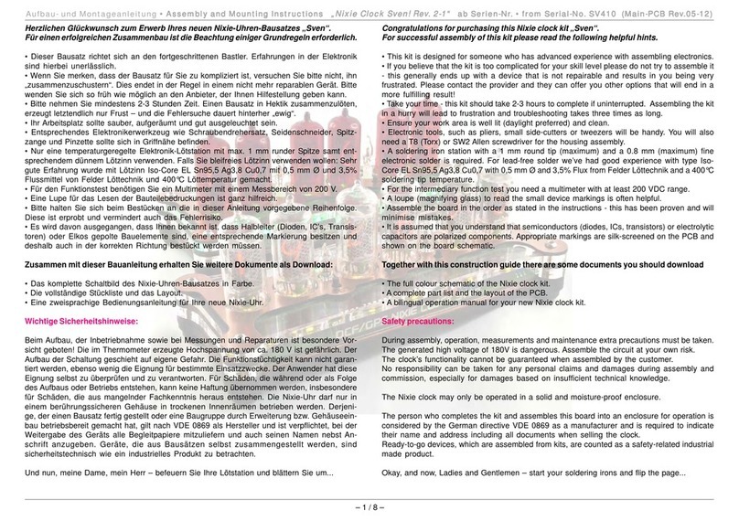
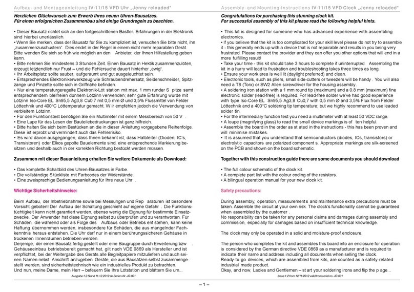
Congratulations for purchasing this stunning Nixie Clock „Manuela_HR“.
For successful assembly of the clock please read the following helpful hints.
This kit is designed for someone who has advanced experience with assembling
electronics - especially working with very fine "filigree" parts.
If you believe that the kit is too complicated for your skill level please do not try to
assemble it - this generally ends up with a device that is not repairable and results in
you being very frustrated. Please contact the provider and they can offer you other
options that will end in a more fulfilling result!
Take your time - this kit should take 2-3 hours to complete if uninterrupted.
Assembling the kit in a hurry will lead to frustration and the troubleshooting afterwards
takes three times as long.
Ensure your work area is well lit (daylight preferred) and clean.
Electronic tools, such as pliers, small side-cutters or tweezers should be handy. You
will also need a T8 (Torx) or SW2 Allen screwdriver for the housing assembly.
A soldering iron with a 1 mm round tip (maximum) and a 0.8 mm (maximum) fine
electronic solder (lead-free) is required.
For the intermediary function test you need a multimeter with at least 200 VDC range.
A loupe to read the small device markings is often helpful.
Assemble the board in the order as stated in the instructions - this has been proven
and will minimize mistakes.
It is assumed that you understand that semiconductors (diodes, ICs, transistors) or
electrolytic capacitors are polarized components. Appropriate markings are silk-
screened on the PCB and shown on the board schematic.
Together with this construction guide you get some additional helpful documents:
The schematic of the clock
A very useful coloured landscape hard copy of the parts placement together with the layout
from top and bottom side and the part list. You should keep this handy during construction as
a reference. All the positions of the resistors, capacitors and semiconductors are shown
enhanced.
A printed operation manual for your Nixie clock. Please keep this manual handy.
Safety precautions:
During assembly, operation, measurements and maintenance extra precautions must be taken. The
generated high voltage of 190V is dangerous. Assemble the circuit at your own risk. The functionality
cannot be guaranteed when assembled by the customer. No responsibility can be taken for any
personal claims and damages during assembly and commission, especially for damages based on
insufficient technical knowledge.
The clock may only be operated in a solid and moisture-proof enclosure.
The person who completes the kit and assembles this board into an enclosure for operation is
considered by the German directive VDE 0869 as a manufacturer and is required to indicate their
name and address including all documents when selling the clock. Ready-to-go devices, which are
assembled from kits, are counted safety-related as an industrial made product.
Okay, and now, Ladies and Gentlemen, start your soldering irons!

Assembly manual „Manuela_HR“ Nixie-clock
Page 2 from 9
1.: Assembly of the board connectors
Please place the PCB solder side up and assemble the ten board connectors from bag 8 as shown in
the picture.
Please have a close look at the picture and do not mismatch male and female connectors or the
direction of the males’ nibbles.
If incorrectly assembled, it is almost impossible, without special tools, to de-solder the connectors
without damaging the board. For better visibility the male connectors are shown in blue and the female
connectors in red.
Important: The pcbs will be separated after the successful powering up of the clock, not before.
Please now remove the four nibbles from the male connectors on the adaptor board (red arrows). You
can easily remove them by bending.
2.: Assembly of the tube LEDs – only for “Desktop” enclosure version
Assemble now the six tube LEDs
from bag 3. Pay attention to their
correct orientation (Anode = long
leg, Cathode = short leg).
Desktop enclosure
As the LEDs are fitted directly on the pcb, solder as fast as
possible from the parts side to positions LED1…6, so as not to
damage the internal chips due to the high temperature.
Office enclosure
Please bend the LED’s leads as shown in the picture and solder them from the solder side to
positions LED11…16.
3.: Installing the resistors
Start installing all the resistors from bag 1. It’s best to start with the most
common resistor (7.5 kohms) and than proceed with the lower quantity ones.
Please note that some resistors are vertically mounted. The ring on the pcb’s
assembly shows you the position of the resistors body (picture).
4.: Assembly of some semiconductors
Next, from bag 2, insert all lower profile parts such as IC sockets (but do not fit the IC themselves),
the MOSFET transistor T17 (Note the correct orientation; the print must not read upside down; also
the Drain pin has two legs, which are tied together; this is shown also on the pcb), the polyfuse R17
and the voltage regulator IC3.

Assembly manual „Manuela_HR“ Nixie-clock
Page 3 from 9
5.: Installation of some capacitors
Note: Please pay careful attention to the correct orientation of all electrolytic capacitors as shown on
the pcb’s assembly print (ring is “-“).
Install from bag 7 all low profile capacitors, these are the 220pF, 1n0 and
100nF ceramic capacitors, the both small 10µF 16V electrolytics and the
0.33F SuperCap capacitor. Take a look at the SuperCap’s correct
orientation shown in the right-hand picture.
Assemble now the LowESR C18 330µF 16V. This capacitor is violet
coloured. Then install the same sized 2µ2 350V C21. Do not mismatch
them with the remaining six “standard” 330µF capacitors and do not
reverse their positions!
The remaining six pcs. “standard” 330µF capacitors will be installed at a later stage.
6.: Assembly of mechanical parts
From bag 9 identify and install some mechanical parts: 3 x push button switches,
slide switch, buzzer, 470µH inductor, crystal and the DC-jack. Due to a pcb
spacing error you must bend the upper pin of the jack a little bit to fit the jack into
the pcb. First, solder this bended pin and then adjust the jack for exact upright
positioning. The spacing between jack and pcb should be max. 1 mm. After
adjusting, solder the two remaining pins. Remove the M8 nut and washer as they
will not be needed.
Attention; The DC jack must fitted at the Desktop version from the top side as usual but at the
Office enclosure the DC jack must be fitted from the solder side as shown in the picture.
7.: The very first electrical test!
Now we will start our first test. Please take a look around your desktop. The following parts should be
left and not fitted at the moment: All multipole integrated circuits, the six “standard” 330µF 16V
capacitors, all 13 MPSA-transistors from bags 5 and 6 and the tubes with their socket pins and the
decimal point LEDs. For reference have a close look at the picture shown below.
Please turn the pcb around again and solder a short wire (e.g. from an off-cut
resistor leg) from the slide-switch pins to the ceramic capacitor as shown in the
right-hand picture.
Now turn the pcb back over and set the LED slide-switch to the “on” position.
Connect the power supply to the circuit and monitor the pcb:
• Keep an eye out for parts that may run hot or “smell like something is burning”.
• Touch carefully the polyfuse R17 (next to the DC jack); it should not be hot.
• All six tube LEDs should light up and if RGB LEDs are fitted, they must start
their colour changing sequences.
Now we can check some generated voltages with your
multimeter. Place the black probe (GND) on the top of the 0.33F
SuperCap as the reference point (shown left). With the red probe
the generated voltage on some test points can be measured.

Assembly manual „Manuela_HR“ Nixie-clock
Page 4 from 9
Set your multimeter to voltage measurement and a range of around 20 VDC.
Check the voltage on testpoint “5V” (right picture). It must be in the range of 5.1…5.5VDC.
Now unplug the power supply and turn the pcb over. Remove the provisional wire from the slide switch
and the capacitor pin. Now solder both solder jumpers labelled “5V” together just below the test points.
Turn around the pcb again and fit all remaining transistors and the six 330µF capacitors C1…C6.
When complete, take some time to carefully inspect your work for any solder bridges or component
placement errors.
Now plug in the MC34063A (IC4) voltage converter.
Decoder IC2 and processor IC1 are not fitted at this time!
Set the slide-switch „LED“ to „off“ and connect the DC power supply to the DC jack again.
Caution: Now the step up converter should work and produces around
190 VDC. At this stage be very carefully during handling the circuity!
Check again if the polyfuse R17 does not run hot. Now the LEDs do not light
up anymore. This is not a fault – so don’t panic.
Put your red probe on the measuring point shown on the right picture, it is the
cathode leg of D16. Check the generated high voltage. It should be in the
range of 180...190 VDC.
Check now all voltages on every pin from both multipole integrated circuit
sockets (the decoder IC1 and the processor IC2). The maximum allowed voltage is 5.5V.
If this test is also finished successfully unplug the clock’s circuit from the power supply and fit now the
both remaining integrated circuits IC1 and IC2.
8.: Fitting the tube sockets.
First take a shallow bowl or a similar pot and put into it all sockets from the bag 10.
First pick up the tube. Now slide on all tube pins the socket pins out of your pot.
Tip: First press gently the socket pins on its upper end with your fingers for a good electrical
contact with the tube pins.
Put the tube aside on a safe place when fitted with all the pins.
Note: With the IN12 tubes only 11 socket pins (and connections) are used.
The pin to the left of the anode pin is not used on the IN12 types (this is the
non-used decimal point).
Please note also that the PCB has also no pad for this Pin (The anode pin has
a white sleeve internally marked.)
Have a look at the right picture.
On the ZM tubes this 12th pin does not exist and therefore this position is left
blank.
Now fit both tubes on the PCB.
Please pay attention of the direction of the tube. The marked anode pin on the
IN-12 tubes must be orientated to the ring marked solder pad on the PCB.
The tall end of all socket pins will easily slide to the pads’ drill holes on the PCB but for the thicker
part of the socket you need a little sense. Depending on the tube sockets tolerances, one or two
socket pins may need a bit of help by tweezers to fit correct in its drill hole.
Please don’t force the tube together with its sockets into the PCB. You’ll need to have a little patience
for this step. Before soldering adjust the tube correctly.
During soldering use as less solder as possible. The socket pins are hollow. If you use too much
solder, the excess solder might flow into the socket pin which will result in soldering the tube to the
socket pin and the PCB.
9. Fitting of the decimal point LEDs
After soldering the two tubes take the decimal point LED’s and the three
spacers* out from its bag. Thread the LED’s through the spacer* and fit this
“combination” into the PCB. Beware of LED orientation again. Do not solder
these LED’s yet. Only bend the LED leads, also do not cut them at this
stage.
Attention: LED7 is not fitted in the Office enclosure version.

Assembly manual „Manuela_HR“ Nixie-clock
Page 5 from 9
* The spacers are only required if ZM tubes are used.
For correct LED adjustment now pick up the front cover. Leave the
protective film! Place the cover over the tubes and slide it down as to
the LED case. Use tweezers to help the LEDs fitting into its cut-outs.
Don’t buckle the cover too hard, it may break! Now solder the LEDs
and cut the leads. Remove the cover.
Now crack only the two adapter cards on the right from the board and fit them at the sockets of the
solder side as shown at the picture.
10.: Final test
Plug again the power supply to the clock.
Caution: 190VDC is present on the board!
Now your clock should start up working with 0:00.00 and counting seconds.
The leading zero is suppressed due to the option settings and the firmware of the pic. So push the
“Adjust” button to bring the six digit date to the display. Now the left-most tube should also light up.
Monitor now for a while the display if all numerals will light up. Sometimes there is an incompletely
soldered contact pin.

Assembly manual „Manuela_HR“ Nixie-clock
Page 6 from 9
11a. Assembling the Desktop enclosure
Remove the power from the clock again. Remove also both adaptor cards and keep them. They will
be very helpful when servicing the clock (but this might not be necessary of course).
First we must mount the four black plastic spacers. Have a look at the photos below how to do that.
Please fasten the spacers only by hand. Do not use any spanner or similar tool!
Now carefully break apart both PCB boards (the Display and Main board) and put the together face to
face with their solder sides. Fix both pcbs with the supplied M3 x 4 screws.
In your kit you found a pre-assembled enclosure. However you should de-assemble this enclosure to
remove the protective films from the Plexiglas frames.
And here’s a design-tip:
When removing both protective films from the Plexiglas you’ll get a fully transparent enclosure. But if
you want a bluish glimmer of the enclosure so you should only remove the protective film from one
side.
On one side of the frame this protective film is always bluish. On the other side the film is either bluish
or bluish with print or frosted white. It’s a little bit difficult to find the “right” side with the only bluish film,
which not may be removed. So have a close look at both photos to find out the right side.
In the left picture, the pure blue film, which you
might prefer to keep on the Plexiglas, is on the
button side, and the film you will always
remove is on the top side.
In the right picture, the pure blue film, which
you might prefer to keep, is on the top side,
and the film you will always remove is on the
button side.

Assembly manual „Manuela_HR“ Nixie-clock
Page 7 from 9
The rear cover is also protected with a film, but only on the outer side (the letters are engraved
mirrored from the inner side, so there’s no protective film on this “engraving side”.
Remove now the protective films from the rear and also from the front cover.
Due to the different size of the ZM and IN tubes, you’ll need a different value of inner frames. For ZM
tubes you’ll need seven pieces, for IN tubes eight frames. Because of the 6 mm more depth when
using eight frames for IN tubes the spacers must mount in a different way:
ZM tubes enclosure: Screw M3 x 8 Ærear cover Æspacer M3 x 17 Æspacer M3 x 25.
IN tubes enclosure: Screw M3 x 8 Ærear cover Ædistance-ring 3 mm Æspacer M3 x 17 Æ
distance-ring 3 mm Æspacer M3 x 25.
Stack the bluish frames in that way onto the
spacers, that the bluish protective film (when
using the “design trick” is facing to the rear,
so you are looking at the non protective
transparent Plexiglas – see also the photo
on the right.
Now apply the tubes board to the enclosure.
Please pay attention for the buttons and the
DC jack on rear that they will fit into their
drilling holes.
Finally fix the board and also the front cover with the four supplied M3 flat hat screws and attach on
button side the four self-adhesive rubber feet.
11.b Assembling the Office Gehäuse
Please remove first from the golden rear
cover both protective films and mount with
four flat hat screws M3x8 the “spacers-
combination” as shown in the right picture.
Please only threaten the screws by hand.
Pay extra attention for correct alignment of
the DJ jack as shown in the picture on the
right.
Spacers M3x12 core / extrenal thread
and M3x12 2x core thread
Spacers M3x15 core / extrenal thread
and M3x18 2x core thread
Drilling for DC-jack

Assembly manual „Manuela_HR“ Nixie-clock
Page 8 from 9
Now remove from all the three supplied mounting frames (1 x
black and 2 x transparent) the protective films and put them over
the spacers. Please not that the black frame must be the first to
put over so it touches the back cover.
Now pick up the assembled board. The distance between board and rear cover is made with four
spacers M3x10. They must be mounted from the solder side of the board and fixed with four screws
M3x6 which are threaded through the drill holes of the board.
It is recommended to remove the tubes when fastening the screws.
Now remove the bolt nut and the washer from the DC jack. Fit now the board in the prepared
enclosure frame. After a slight adjusting the DC jack must fit though its holes in the rear cover. Now fix
the board with four M3x8 flat hat screws. Now screw again washer and bolt nut to the DC jack. Don’t
use any tools for that, screw only by hand, as you might scratch the golden coating.
Now refit the tubes.
Remove now from the engraved front cover the protective film from the rear side and mount it on the
spacers. Pay attention that all buttons will fit into their drill holes. Fit it with two M3x8 flat hat srews at
the lower shorter spacers.
At least remove the protective films from the transparent display frame and from the front cover and
put them over the remaining upper longer spacers. Fit them with the remaining two M3x8 flat hat
screws. After adding the four rubber feeds to the bottom of the clock and mounting the stand clamp on
rear the assembling of your Office clock is finished.
Congratulations!

Assembly manual „Manuela_HR“ Nixie-clock
Page 9 from 9
Vendor
This clock kit was carefully engineered and assembled in Germany by
Jürgen Grau • Feiningerweg 28/1 • 72622 Nürtingen • Germany
Fon: +49 / 7022 / 7896886 • Fax: +49 / 7022 / 90 44 03
E-Mail: [email protected]
Do you have any suggestions? Don’t hesitate and contact me.
Troubleshooting
When you are reading this paragraph than you clock does not work as expected.
If you need to de-solder some parts, never try to clean the pads with a solder sucker or similar and
than trying to pull out the part. This will not work and will result in damaging the pads and / or the
board.
Always heat up all pins together from the removing part (with sufficient solder wire) and pull out the
heated part. After removing you can clean the pads from solder with your solder sucker.
Some faults just at the beginning of the testing procedure:
The LEDs does not light up and the polyfuse R17 runs hot.
Certainly the MosFet transistor is fitted the wrong way round or is damaged due to ESD.
The LEDs does not light up and the R17 remains cold (no current consumption at all).
Diodes D7…D10 or the LEDs fitted the wrong way round. Slide switch is set to “off”,
preliminary wire at the switch position is not soldered correct to the GND pin of the capacitor.
The 5V voltage is too high, around 9V or some more.
IC3 fitted the wrong way round or was mistaken with a transistor. D14 is fitted the wrong way
round or missing.
Some faults when generating the high voltage
The voltage is much too low but more than 12V, R32 is running hot.
Have you really removed the preliminary wire at the switch?
The voltage is much too low but more than 12V, inductor and MosFet are running hot.
Is the value of R24 and C20 correct?
The generated voltage is in its range but R32 runs hot.
Check if one of the transistors T1…T6 has a short circuit.
Too high voltage (more than 5.5V) on some pins of the pic or the decoder
Check the connected transistor T1…T7 for a Base-Emitter short circuit. This is sometimes a problem
with the MPSA42. They will start to “zener” only when connected to high voltage. During measuring
with a simple “low voltage” ohmmeter they look free from defects. So if you suggest such a fault, just
keep the clock running during measuring the voltage over the transistor’s pins but be carefully due to
the surrounding high voltage.
Faulty display
One tube lights up very bright, and all digits are also turned on together.
Check the connected transistor T11…T16 for a short circuit.
One tube does not light up anymore.
If swapping with a non-faulty tube does not help check for correct value of the resistors
R11…R16. Check also for short circuits of the transistors connected to the tube’s Anode.
… To be continued …


Stückliste / Part List Manuela HR Nixie Clock
1. Uhrenbausatz / Clock kit
Nr. Inhalt
Content Beschreibung
Description Code Stück
Pieces
100R R19,R20,R25 3
330R R23,R24,R30,R32 4
1k8 R27,R28,R29,R31 4
560k R11,R12,R13,R14,R15,R16,R22,R26 8
7k5 R1,R2,R3,R4,R5,R6,R7,R8,R9,R10,R18,R21 12
1 Widerstände
Resistors
Polyfuse R17 1
1N5819 D7,D8,D9,D10 4
BAT42 D11,D12,D13,D14,D15,D17,D18 7
UF4004 D16 1
78L05 IC3 1
K155ID1 IC2 1
PIC16F628 IC1 1
MC34063A IC4 1
IRFD220 T17 1
IC Sockel / Socket 8-pol. 1
IC Sockel / Socket 16-pol. 1
2 Halbleiter
Semicond.
IC Sockel / Socket 18-pol. 1
3 LEDs für Röhrenbeleuchtung
LEDs for tubes lighting LED1,LED2,LED3,LED4,LED5,LED6 oder/or
LED11,LED12,LED13,LED14,LED15,LED16 6
LED für Punkte / for Points LED7,LED8,LED9 3
4 LED-Distanzen / LED Spacers nur ZM-Ausführung / only ZM version 3
5 MPSA 42 NPN HV Transistor T1,T2,T3,T4,T5,T6,T7 7+1
6 MPSA 92 PNP HV Transistor T11,T12,T13 ,T14,T15,T16 6+1
27pF “27“ C11,C12 2
1nF „K1K“ C20 1
100nF „104“ C7,C8,C13,C14,C15,C17,C22 7
2µF 350V C21 1
330µF low ESR C18 1
10µF 16V C9,C10 2
330µF 16V C1,C2,C3,C4,C5,C6 (extra Tüte / bag) 6
7 Kodensatoren
Capacitors
0.33F Supercap C16 1
MM FL10G Buchsenleiste / female BU1,BU2,BU4,BU5 4
8 Verbinder
Connectors MM SL10G Stiftleiste / male ST1,ST2,St3,ST4,ST5,ST6 6
Schiebeschalter / Slide switch S4 1
Drucktaster / Button switch 17mm S1,S2,S3 3
Summer / Buzzer 42ohm passiv SND1 1
DC-Buchse / DC jack HEBL21 BU3 1
Spule / Inductor 470µH L1 1
9 Divers
Quarz / Crystal 4.000MHz Q1 1
10 Röhrensockelstifte / Tube socket Pins > 66
11 Leiterplatte / PCB 1
12 Anleitung / Manual 1
13 Schaltnetzteil / Switching Power Supply 1
2. Desktop Gehäuse / Enclosure
St./pcs. ZM Röhren / Tubes St./pcs. IN Röhren / Tubes
1 Frontseite / Frontcover IN 1 Frontseite / Frontcover IN
7 Zwischenteile / Inner 8 Innenteile / Inner
1 Rückseite / Backcover 1 Rückseite / Backcover
6 Schrauben / Screws M3 x 8 6 Schrauben / Screws M3 x 8
2 Distanzen / Spacers M3 x 17 2 Distanzen / Spacers M3 x 17
2 Distanzen / Spacers M3 x 25 2 Distanzen / Spacers M3 x 25
2 Distanzen / Spacers M3 x 6 2 Distanzen / Spaces M3 x 6
2 Distanzen / Spacers M3 x 12 2 Distanzen / Spacers M3 x 12
4 Distanzen / Spacers M3 x 3
2 Schrauben / M3 x 4 2 Schrauben / M3 x 4
4 Gerätefüße / Rubber feeds 4 Gerätefüße / Rubber feeds
1 Pa. Bauwollhandschuhe / gloves 1 Pa. Bauwollhandschuhe / gloves


5
5
4
4
3
3
2
2
1
1
D D
C C
B B
A A
K9
K8
K7
K6
K5
K4
K3
K2
K1
K0
K9
K8
K7
K6
K5
K4
K3
K2
K1
K0
K9
K8
K7
K6
K5
K4
K3
K2
K1
K0
K9
K8
K7
K6
K5
K4
K3
K2
K1
K0
K9
K8
K7
K6
K5
K4
K3
K2
K1
K0
K9
K8
K7
K6
K5
K4
K3
K2
K1
K0
K0
K1
K2
K4
K6
K3
K5
K7
K8
K9
5V3
185V
5V0
5V0
5V3 5V0
185V
Title
Size Document Number Rev
Date: Sheet of
Schematic 1-11
IN-12 / ZM 1100 / ZM 1080 Nixie clock Manuela HR
11Sunday, February 13, 2011
Title
Size Document Number Rev
Date: Sheet of
Schematic 1-11
IN-12 / ZM 1100 / ZM 1080 Nixie clock Manuela HR
11Sunday, February 13, 2011
Title
Size Document Number Rev
Date: Sheet of
Schematic 1-11
IN-12 / ZM 1100 / ZM 1080 Nixie clock Manuela HR
11Sunday, February 13, 2011
LED on/off
5V
Low ESR
ALARM
Fit LED1...6 when used as desktop clock
Fit LED11...16 when used as a wall clock
350V
BU2-6BU2-6
C14
100nK
C14
100nK
C10
10u
C10
10u
R16
560k
R16
560k ST2-6ST2-6
5V5V
ST2-8ST2-8
T6
MPSA42
T6
MPSA42
H5H5
A
1
02
93
84
75
66
57
48
39
210
111
DP 12
BU2-8BU2-8
C8
100nK
C8
100nK
D9
1N5819
D9
1N5819
S2
SET
S2
SET
H3H3
A
1
02
93
84
75
66
57
48
39
210
111
DP 12
R10
7k5
R10
7k5
BU2-10BU2-10
D8
1N5819
D8
1N5819
T16
MPSA92
T16
MPSA92
T1
MPSA42
T1
MPSA42
R8
7k5
R8
7k5
R6 7k5R6 7k5
BU1-6BU1-6
R27 1k8R27 1k8
ST1-10ST1-10
R32
330R
R32
330R
H2H2
A
1
02
93
84
75
66
57
48
39
210
111
DP 12
R22
560k
R22
560k
C1
330µ
C1
330µ
ST2-9ST2-9
ST3-1ST3-1
R28 1k8R28 1k8
R13
560k
R13
560k
BU2-5BU2-5
C20
1nK
C20
1nK
T3
MPSA42
T3
MPSA42
ST3-10ST3-10
ST1-6ST1-6
BU1-5BU1-5
T13
MPSA92
T13
MPSA92
LED3LED3
Q1
4MHz
Q1
4MHz
R9
7k5
R9
7k5
C4
330µ
C4
330µ
C9
10u
C9
10u
ST4-10ST4-10
ST2-4ST2-4
IC4
MC34063A
IC4
MC34063A
SC
1SE
2TC
3GND
4
DC 8
IS 7
VCC 6
CI 5
AC2AC2
LED5LED5
T2
MPSA42
T2
MPSA42
R1 7k5R1 7k5
D7
1N5819
D7
1N5819
ST4-8ST4-8
BU2-1BU2-1
C16
0.33F
C16
0.33F
C18
330u
C18
330u
R7
7k5
R7
7k5
D13
BAT42
D13
BAT42
ST1-8ST1-8
BU1-1BU1-1
R30
330R
R30
330R
IC1
Nixieclock2011
IC1
Nixieclock2011
BCD-C 1
BCD-D 2
BCD-A 17
BCD-B 18
NEONS 3
HRSx10 11
HRSx1 10
MINSx10 9
MINSx1+ADV 8
SECSx10+SET 7
SECSx1+MODE 6
SOUND
13
MCLR
4
KEY-INPUT
12
XTAL1
15
XTAL2
16
VDD
14
GND
5
D17
BAT42
D17
BAT42
BU2-2BU2-2
BU2-9BU2-9
C12 27pC12 27p
ST2-3ST2-3
ST3-4ST3-4
ST1-9ST1-9
LED9LED9
D10
1N5819
D10
1N5819
BU2-4BU2-4
LED11LED11
BU1-2BU1-2
ST4-9ST4-9
R5 7k5R5 7k5
R23 330RR23 330R
T7
MPSA42
T7
MPSA42
R14
560k
R14
560k
ST2-2ST2-2C2
330µ
C2
330µ
R3 7k5R3 7k5
ST1-4ST1-4
ST3-8ST3-8
ST4-7ST4-7
ST3-9ST3-9
T4
MPSA42
T4
MPSA42
AC1AC1
R25 100RR25 100R
LED12LED12
H4H4
A
1
02
93
84
75
66
57
48
39
210
111
DP 12
T14
MPSA92
T14
MPSA92
IC3 78L05IC3 78L05
IN GND
OUT
L1
470uH
L1
470uH
S3
MODE
S3
MODE
ST3-2ST3-2
C5
330µ
C5
330µ
R11
560k
R11
560k
BU1-8BU1-8
H6H6
A
1
02
93
84
75
66
57
48
39
210
111
DP 12
ST3-7ST3-7
ST1-1ST1-1
H1H1
A
1
02
93
84
75
66
57
48
39
210
111
DP 12
ST2-1ST2-1
R26
560k
R26
560k
LED1LED1
R21
7k5
R21
7k5
BU1-9BU1-9
ST4-4ST4-4
LED16LED16
D16
UF4004
D16
UF4004
LED4LED4
R29 1k8R29 1k8
ST2-7ST2-7
ST4-2ST4-2
C22
100nK
C22
100nK
ST2-5ST2-5
R19
100R
R19
100R
C17
100nK
C17
100nK
ST1-7ST1-7
T17
IRFD220
T17
IRFD220
T11
MPSA92
T11
MPSA92
ST4-1ST4-1
BU2-7BU2-7
ST3-5ST3-5
R18
7k5
R18
7k5
ST3-3ST3-3
C15
100nK
C15
100nK
LED8LED8
BU1-10BU1-10
R12
560k
R12
560k
ST4-3ST4-3
C6
330µ
C6
330µ
ST3-6ST3-6
T5
MPSA42
T5
MPSA42
D12
BAT42
D12
BAT42
ST2-10ST2-10
C11 27pC11 27p
BU2-3BU2-3
ST1-3ST1-3
ST4-5ST4-5
D14
BAT42
D14
BAT42
T12
MPSA92
T12
MPSA92
R15
560k
R15
560k
SND1SND1
T15
MPSA92
T15
MPSA92
D11
BAT42
D11
BAT42
S1
ADJ
S1
ADJ
LED13LED13
ST4-6ST4-6
LED2LED2
D18
BAT42
D18
BAT42
R20
100R
R20
100R
BU1-3BU1-3
BU1-7BU1-7
LED14LED14
R24
330R
R24
330R
C13
100nK
C13
100nK
C3
330µ
C3
330µ
ST1-5ST1-5
LED7LED7
BU3BU3
D15
BAT42
D15
BAT42
C7
100nK
C7
100nK
R31
1k8
R31
1k8
S4S4
R4 7k5R4 7k5
R2 7k5R2 7k5
C21
2u2
C21
2u2
IC2
K155ID1
IC2
K155ID1
A
3B
6C
7D
4
VCC 5
GND
12
016
115
28
39
413
514
611
710
81
92
LED15LED15
R17
0.5A
R17
0.5A
BU1-4BU1-4
ST1-2ST1-2
LED6LED6


Other manuals for Manuela HR
1
Other Mr. Nixie Clock manuals

Mr. Nixie
Mr. Nixie Jenny reloaded Quick start guide

Mr. Nixie
Mr. Nixie Strawberry User manual

Mr. Nixie
Mr. Nixie Manuela HR User manual

Mr. Nixie
Mr. Nixie Strawberry IN-28 User manual

Mr. Nixie
Mr. Nixie NUMIQUEEN IV-13 User manual

Mr. Nixie
Mr. Nixie Anita User manual

Mr. Nixie
Mr. Nixie IV-12 VFD-Clock Jenny User manual

Mr. Nixie
Mr. Nixie Lars User manual

Mr. Nixie
Mr. Nixie Anita User manual

Mr. Nixie
Mr. Nixie SV410 Quick start guide