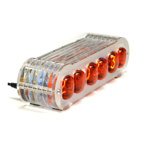
Mr. Nixie Jenny reloaded Quick start guide

Aufbau- und Montageanleitung IVIV
IVIV
IV-11/15-11/15
-11/15-11/15
-11/15 VFD Uhr „JVFD Uhr „J
VFD Uhr „JVFD Uhr „J
VFD Uhr „Jennenn
ennenn
enny ry r
y ry r
y reloaded“eloaded“
eloaded“eloaded“
eloaded“ Assembly- and Mounting-Instructions IVIV
IVIV
IV-11/15-11/15
-11/15-11/15
-11/15 VFD ClocVFD Cloc
VFD ClocVFD Cloc
VFD Clock „Jk „J
k „Jk „J
k „Jennenn
ennenn
enny ry r
y ry r
y reloaded“eloaded“
eloaded“eloaded“
eloaded“
– 1 –
Herzlichen Glückwunsch zum Erwerb Ihres neuen Uhren-Bausatzes.
Für einen erfolgreichen Zusammenbau sind einige Grundregeln zu beachten.
• Dieser Bausatz richtet sich an den fortgeschrittenen Bastler. Erfahrungen in der Elektronik
sind hierbei unerlässlich.
• Wenn Sie merken, dass der Bausatz für Sie zu kompliziert ist, versuchen Sie bitte nicht, ihn
„zusammenzuschustern“. Dies endet in der Regel in einem nicht mehr reparablen Gerät.
Bitte wenden Sie sich so früh wie möglich an den Anbieter, der Ihnen Hilfestellung geben
kann.
• Bitte nehmen Sie mindestens 3 Stunden Zeit. Einen Bausatz in Hektik zusammenzulöten,
erzeugt letztendlich nur Frust – und die Fehlersuche dauert hinterher „ewig“.
• Ihr Arbeitsplatz sollte sauber, aufgeräumt und gut ausgeleuchtet sein.
• Entsprechendes Elektronikerwerkzeug wie Schraubendrehersatz, Seidenschneider, Spitz-
zange und Pinzette sollte sich in Griffnähe befinden.
• Nur eine temperaturgeregelte Elektronik-Löt station mit max. 1 mm runder S pitze samt
entsprechendem bleifreien dünnem Lötzinn verwenden; sehr gute Erfahrung wurde mit
Lötzinn Iso-Core EL Sn95,5 Ag3,8 Cu0,7 mit 0,5 mm Ø und 3,5% Flussmittel von Felder
Löttechnik und 400°C Löttemperatur gemacht. W ir empfehlen jedoch die V erwendung von
verbleitem Lötzinn.
• Für den Funktionstest benötigen Sie ein Multimeter mit einem Messbereich von 50 V .
• Eine Lupe für das Lesen der Bauteilebedruckungen ist ganz hilfreich.
• Bitte halten Sie sich beim Bestücken an die in dieser Anleitung vorgegebene Reihenfolge.
Diese ist erprobt und vermindert auch das Fehlerrisiko.
• Es wird davon ausgegangen, dass Ihnen bekannt ist, dass Halbleiter (Dioden, IC’s,
Transistoren) oder Elkos gepolte Bauelemente sind, eine entsprechende Markierung be-
sitzen und deshalb auch in der korrekten Richtung bestückt werden müssen.
Zusammen mit dieser Bauanleitung erhalten Sie weitere Dokumente als Download:
• Das komplette Schaltbild des Uhren-Bausatzes in Farbe.
• Die vollständige S tückliste mit Farbcodes der Widerstände.
• Eine zweisprachige Bedienungsanleitung für Ihre neue Uhr .
Wichtige Sicherheitshinweise:
Beim Aufbau, der Inbetriebnahme sowie bei Messungen und Rep araturen ist besondere
Vorsicht geboten! Der Aufbau der Schaltung geschieht auf eigene Gefahr . Die Funktions-
tüchtigkeit kann nicht garantiert werden, ebenso wenig die Eignung für bestimmte Einsatz-
zwecke. Der Anwender hat diese Eignung selbst zu überprüfen und zu verantworten. Für
Schäden, die während oder als Folge des Aufbaus oder Betriebs ent stehen, kann keine
Haftung übernommen werden, insbesondere für Schäden, die aus mangelnder Fach-
kenntnis heraus entstehen. Die Uhr darf nur in einem berührungssicheren Gehäuse in
trockenen Innenräumen betrieben werden.
Derjenige, der einen Bausatz fertig gestellt oder eine Baugruppe durch Erweiterung bzw .
Gehäuseeinbau betriebsbereit gemacht hat, gilt nach VDE 0869 als Hersteller und ist
verpflichtet, bei der Weitergabe des Geräts alle Begleitpapiere mitzuliefern und auch sei-
nen Namen nebst Anschrift anzugeben. Geräte, die aus Bausätzen selbst zusammenge-
stellt werden, sind sicherheitstechnisch wie ein industrielles Produkt zu betrachten.
Und nun, meine Dame, mein Herr – befeuern Sie Ihre Lötstation und blättern Sie um...
Ausgabe1.2 Stand11.12.2012abSerien-Nr.JR-001
Congratulations for purchasing this stunning clock kit.
For successful assembly of this kit please read the following helpful hints.
• This kit is designed for someone who has advanced experience with assembling
electronics.
• If you believe that the kit is too complicated for your skill level please do not try to assemble
it - this generally ends up with a device that is not repairable and results in you being very
frustrated. Please contact the provider and they can offer you other options that will end in a
more fulfilling result!
• Take your time - this kit should t ake 3 hours to complete if uninterrupted. Assembling the
kit in a hurry will lead to frustration and troubleshooting takes three times as long.
• Ensure your work area is well lit (daylight preferred) and clean.
• Electronic tools, such as pliers, small side-cutters or tweezers will be handy . You will also
need a T8 (Torx) or SW2 Allen screwdriver for the housing assembly.
• A soldering iron station with a 1 mm round tip (maximum) and a 0.8 mm (maximum) fine
electronic solder (lead-free) is required. For lead-free solder we’ve had good experience
with type Iso-Core EL Sn95,5 Ag3,8 Cu0,7 with 0,5 mm Ø and 3,5% Flux from Felder
Löttechnik and a 400°C soldering tip temperature; but we highly recommend to use leaded
solder tin.
• For the intermediary function test you need a multimeter with at least 50 VDC range.
• A loupe (magnifying glass) to read the small device markings is of ten helpful.
• Assemble the board in the order as st ated in the instructions - this has been proven and
will minimise mistakes.
• It is assumed that you understand that semiconductors (diodes, ICs, transistors) or
electrolytic capacitors are polarized component s. Appropriate markings are silk-screened
on the PCB and shown on the board schematic.
Together with this construction guide there are some documents you should download
• The full colour schematic of the clock kit.
• A complete part list with the colour coding of the resistors.
• A bilingual operation manual for your new clock kit.
Safety precautions:
During assembly, operation, measurement s and maintenance extra precautions must be
taken. Assemble the circuit at your own risk. The clock’s functionality cannot be guaranteed
when assembled by the customer .
No responsibility can be taken for any personal claims and damages during assembly and
commission, especially for damages based on insufficient technical knowledge.
The clock may only be operated in a solid and moisture-proof enclosure.
The person who completes the kit and assembles this board into an enclosure for operation
is considered by the German directive VDE 0869 as a manufacturer and is required to
indicate their name and address including all documents when selling the clock.
Ready-to-go devices, which are assembled from kits, are counted as a safety-related
industrial made product.
Okay, and now, Ladies and Gentlemen – st art your soldering irons and flip the p age...
Issue1.2 from12/11/2012validfrom serialno. JR-001


–Englishtextseefollowingpage–
TechnischeProblememitderJennyReloadedVFDUhr
Bitteaufmerksamlesen!
BeieinigenUhrenergabsichentwedersofortodererstnacheinigerBetriebszeitdasProblem,dass
derMosFetT2heißwurdeunddieUhrnichtmehrfunktionierte.Gleichzeitigverfärbtensich
aufgrundvoneineminternenKurzschlussC13und/oderC20underhitzensichstark.
Eswurdeherausgefunden,dassdieseKeramik‐KondensatorenauseinerChargestammen,diedie
47VBetriebsspannung(dieKondensatorensindmit50Vspezifiziert)aufDauernichtverkrafteten.
BitteüberprüfenSiezuerst,mitwelchenKondensatorenIhreUhrausgeliefertwurdewiefolgt:
TrennenSiedieUhrvomStromund
schraubenSiedieLeiterplatte
heraus.FindenSiediePositionen
vonC13undC20anhandderAb‐
bildungenundsehenSiesichdie
Kondensatorenan.
"Guter"Kondensator"Schlechter"Kondensator
EinHandelnIhrerseitsKondensatorenC13undC20
istnichterforderlich.müssenausgelötetwerden.
DieUhristmitinsgesamtachtdieser100nFKondensatorenbestückt;entwederdie"linke"oder
die"rechte"Ausführung.DerAusfallbetrifftjedochnurC13und/oderC20;d.h.dassdieanderen
sechs"schlechten"KondensatoreninderLeiterplattebelassenwerdenkönnen.
ZumAuslötenderKondensatorenC13/C20gehenSiewiefolgtvor:
ErhitzenSiediebeidenLötaugenproKondensatorgleichzeitigunterZugabevonLötzinnund
ziehenSiedieKondensatoren,z.B.miteinerPinzette,heraus.DanachöffnenSiedieBohrlöcher
miteinerEntlötpumpe.MitdieserMaßnahmeistIhreUhrvorläufigwiederbetriebsbereit,eswird
jedochdringendempfohlen,C13undC20wiederdurch100nF/100VVersionenzuersetzen.
Weiterhinwurdefestgestellt,dassC5undC6amRandeihrerSpezifikationen(je25V)betrieben
werden.BislangsindkeineProblemenbekanntgeworden,jedochwirdempfohlen,diesenbeiden
Elkosjeeinen47kOhmparallelzuschalten,umeinebessereSpannungs‐Symmetriezuerreichen.
DerHerstellerbietetaufWunscheinkostenlosesUpgrade‐Set,bestehendaus2xKeramik‐
Kondensatoren100nF/100Vund2x020447kOhmWiderständenan.BittenehmenSie
DieseModifikationenbetreffenausschließlichUhrenbisSerien‐Nr.:JR‐267
AbSerien‐Nr.:JR‐268sindentsprechendeVerbesserungenvorgenommenworden.

TechnicalissueswithJennyReloadedVFDclock
Pleasereadcarefully!
OnsomeJennymodelsanissueoccuredeitheratonceoraftersometimeofoperationthatthe
MosFetT2runshotandtheclockwasnotfunctionalanymore.AtthesametimeC13and/orC20
becamediscoloredandalsorunsveryhotbecauseofaninternalshortcircuit.Itwasdetectedthat
thisceramiccapacitorsweretakenfromabatch,whichisunabletowithstandthe47Voperating
voltage(thespezificationofthecapacitorsis50V)foralongertime.
Pleasecheckfirst,whichtypeofcapacitorstheclockisequippedasfollows:
Disconnecttheclockfrompower
andunscrewoutthePCB.
LocatenowthepositionsofC13
andC20withthehelpofbothleft
illustrationsandcheckthetypeof
thecapacitors.
"Good"capacitor"Bad"capacitor
NomodificationsCapacitorsC13andC20
needtobemade.needstobeun‐soldered.
Theclockisequippedintotalwitheightofthis100nFcapacitors;eitherthe"left"orthe"right"
version.ThepossibilityofafailureonlycanhappensonC13and/orC20;whichmeansthatthe
remainingsix"bad"capacitorscanberemainsolderedin.
Forde‐solderingcapacitorC13/C20pleasedothefollowingtask:
Heatupbothsolderpadsofeachcapacitorsimultaneouswiththehelpofafatdropofsoldertin
andpulloutthecapacitorswithtweezers.Nextcleanallpadswithade‐solderingpump.
Withthismethodyourclockistemporarlyfunctional,butitisstronglyrecommendedtoreplace
C13andC20with100nF/100Vversions.
Furthermoreitwasmentioned,thatbothelectrolytcapacitorsC5andC6aredrivennearlyoutside
theirvoltagerange(25Veach).Noissueswerereportedsofar,anywayitisrecommededtosolder
bothelectrolytcapacitorsaresistorof47kohmseachinparallelforimprovedvoltage‐symmetry.
Onrequestthemanufactureroffersafreeupgradeset,composedof2xceramiccapacitors
100nF/100Vand2x47kohmssmallsizedresistors.Pleasecontactthemanufacturerviaemail
at[email protected].
Thesemodificationsonlyaffectclocksuptoserial‐no.JR‐267
Startingfromserial‐no.JR‐268adequateimprovementshasbeenmade.

Aufbau- und Montageanleitung IVIV
IVIV
IV-11/15-11/15
-11/15-11/15
-11/15 VFD Uhr „JVFD Uhr „J
VFD Uhr „JVFD Uhr „J
VFD Uhr „Jennenn
ennenn
enny ry r
y ry r
y reloaded“eloaded“
eloaded“eloaded“
eloaded“ Assembly- and Mounting-Instructions IVIV
IVIV
IV-11/15-11/15
-11/15-11/15
-11/15 VFD ClocVFD Cloc
VFD ClocVFD Cloc
VFD Clock „Jk „J
k „Jk „J
k „Jennenn
ennenn
enny ry r
y ry r
y reloaded“eloaded“
eloaded“eloaded“
eloaded“
– 2 –
Wir beginnen mit dem Bestücken der Bauteile mit niedriger Bauhöhe. S tarten Sie mit den
Widerständen und hier am besten mit denjenigen, die am meisten in der Schaltung vor-
kommen. Bestücken Sie immer zuerst einen Wert komplett, bevor Sie den nächsten
Widerstandswert nehmen. R15 und R17 werden verikal eingesetzt und jetzt noch nicht
bestückt! Bestücken Sie jetzt auch nicht R14. Beachten Sie auch die beiden Induktivitäten
L2 und L3, dass Sie diese nicht mit den 1 kOhm Widerständen verwechseln. Seien Sie
auch vorsichtig beim Abbiegen der Anschlussbeine des Quarzes. Bestücken Sie dann die
beiden Dioden und achten Sie auf die Lage des weißen Rings. Die „Polung“ der sechs
Arrays RN1...6, ist unbedeutend. Danach bestücken Sie die USB-Buchse (Tipp: Fixieren
Sie die Buchse, indem Sie einen Pin am Gehäuse von der Bauteileseite aus anlöten). Als
nächstes werden alle Keramik-Kondensatoren bestückt und anschließend die beiden läng-
lichen IC-Fassungen. Achten Sie hier besonders auf die Lage der Nase in den Fassungen.
We will start with the low profile electronic parts; so let’s start with the resistors and here it
is best to start with those values which are mostly commonly used in the circuit. First finish
assembling one value before you pick up the next. R15 and R17 are mounted upright and
may not assembled at this stage! Do also not fit R14 yet. Please do also not mismatch both
inductors L2 and L3 with the 1 kohms resistors.
Please be also carefully when beding the crystal’s leads. Next is to assemble both diodes.
Note the polarity which is marked with a white ring on the diodes package.
The “polarity” of the six resistor arrays RN1...6, which are assembled next, is negligable.
Next step is to assemble the USB jack (Tip: Solder one of the case’s pads from the component
side to fix the part).
Following assemble all ceramic cap acitors and than both oblong IC-socket s. Take special
care for the notches at the sockets.
STOP
Ein paar Worte zur verwendeten Leiterplatte
Dies ist eine sog. 4-Lagen Leiterplatte. Das bedeutet, dass sich Leiterbahnen nicht
wie üblich nur auf der Bauteile- und Lötseite befinden, sondern auch noch „inner-
halb“ in der Leiterplatte auf zwei zusätzlichen Lagen. Sie werden dies beim Löten
bemerken, dass Sie ein wenig mehr Zeit benötigen, bis das Lötzinn sauber fließt.
Im Umkehrschluss bedeutet dies, dass Sie mit einer mechanischen Lötpumpe
oder Entlötlitze die Bauteile NICHT MEHR auslöten können ohne das Board zu
zerstören. Falls Sie einen Bestückungsfehler gemacht haben, lesen Sie bitte unbe-
dingt die Tipps zum Auslöten auf der letzten Seite.
Some words about the printed circuit board
This is a so-called 4-layer PCB, which means that copper tracks are not only present
on the component and solder site, but also the "inside" of the printed circuit board on
two additional inner layers. You will notice this when soldering as you'll need a little
bit more time until the solder flows.
On the other hand, this means also that you CANNOT DESOLDER components with
a mechanical de-soldering pump or soldering wick without screwing up the board.
If you have made an assembly fault, please read the tips for de-soldering on the last
page of this assembly manual.
!4n7 !100n
Nase / Notch
Nase / Notch
Hier zuerst anlöten / Solder here firstInduktivitäten / Inductors
Ring Ring
R14 hier nicht bestücken
Do not fit R14 on this position

Aufbau- und Montageanleitung IVIV
IVIV
IV-11/15-11/15
-11/15-11/15
-11/15 VFD Uhr „JVFD Uhr „J
VFD Uhr „JVFD Uhr „J
VFD Uhr „Jennenn
ennenn
enny ry r
y ry r
y reloaded“eloaded“
eloaded“eloaded“
eloaded“ Assembly- and Mounting-Instructions IVIV
IVIV
IV-11/15-11/15
-11/15-11/15
-11/15 VFD ClocVFD Cloc
VFD ClocVFD Cloc
VFD Clock „Jk „J
k „Jk „J
k „Jennenn
ennenn
enny ry r
y ry r
y reloaded“eloaded“
eloaded“eloaded“
eloaded“
– 3 –
!
Crack
!
1mm
!
Bestücken Sie nun die höheren Bauteile. Beginnen Sie mit der 3,5 mm Klinken-
buchse, gefolgt von der EMV -Drossel und der 47 μH Spule. Speziell bei dieser
müssen Sie sehr lange das Pad erwärmen, bis das Lötzinn sauber fließt. V erlöten
Sie zuerst ein Pad, richten durch erneutes Erwärmen die S pule sauber aus und
verlöten dann das andere. Als nächstes bestücken Sie die Transistoren. Achtung,
diese Bauteile sind elektrostatisch sehr empfindlich. Bevor Sie die Transistoren
berühren, sollten Sie sich an einem Metallgegenstand vorher entladen. Beachten
Sie besonders deren Einbaurichtung gemäß dem Aufdruck und der Abbildung.
Danach bestücken Sie alle Elektrolyth-Kondensatooren. Beginnen Sie am besten
in der Reihenfolge: 4 x 100 μF, dann den 0,33F SuperCap - bitte beachten Sie hier
die auf der Unterseite zu lötenden Brücken gemäß nebenstehender Abbildung und
löten Sie den SuperCap mit ca. 1 mm Abstand zur Bestückungsseite ein. Bestü-
cken Sie jetzt die abgewinkelten Elkos. Achten Sie vor dem Abwinkeln unbedingt auf
die korrekte Polung. Der „-“ Anschluss zeigt immer zur Rückseite. Wichtig: der
große 2200 μF Kondensator muss so eingesetzt werden, dass er rund 1 mm auf
der Unterseite der Leiterplatte herausschaut (Abbildung). Bitte drücken Sie nicht zu
stark, um den schmalen S teg an Ende der Leiterplatte nicht zu zerstören; darin
befinden sich Leiterbahnen! Zum Schluss setzen wir den PLCC28 Sockel ein. Bitte
prüfen Sie lieber dreimal, ob er „richtig gepolt“ mit der Kerbe nach links unten
eingesetzt ist, bevor Sie ihn verlöten. Er kann im Nachhinein nicht mehr ausgelötet
werden, ohne die Leiterplatte zu zerstören, selbst mit einer professionellen Entlöt-
Station.
!
Brücken löten
Solder jumpers
Keine Gewalt beim Einsetzen
No force when mounting
Start now assembling the higher parts. Start with the 1/8“ Stereo TRS jack, followed
by the EMV inductor left hand and the 47uH inductor. Specially when soldering this
part you need to heat up the pads a longer time until the solder tin smelts. Solder
first only one pad; if necessary allign the inductor by re-heating this pad. Next
solder the second pad.
Next step is to assemble the transistors. Be carfule, as this are electrostatic sen-
sitive MosFets. So you should be first „discharged“ by touching a metall part before
assembling these transistors. Keep special care for their correct oriantation
according to the silk screen and the figure.
Next assemble all electrolythic capacitors. Start in following order: 4 x 100uF, 0.33F
Super Cap - take extra care to solder three jumper as on the left picture shown and
solder this capacitor with around 1 mm spacing between the component side and
the capacitor’s package. Now assemble all angled cap acitor. Before bending the
leads take care for correct polarity. The „-“ lead of all capacitors always points to the
rear side of the board.
Note that the 2,200uF capacitor must be assembled in the way as shown in the left
picture. Be careful not to ruin the small support at the rear side of the PCB as it
cunduct tracks!
Finally we assemble the PLCC28 socket. Please „tripple-check“ as he is correct
inserted with it’s notch as shown in the picture. If soldered the wrong way it is
impossible to de-solder this socket without screwing up the board; even with a
professional desoldering iron.

Aufbau- und Montageanleitung IVIV
IVIV
IV-11/15-11/15
-11/15-11/15
-11/15 VFD Uhr „JVFD Uhr „J
VFD Uhr „JVFD Uhr „J
VFD Uhr „Jennenn
ennenn
enny ry r
y ry r
y reloaded“eloaded“
eloaded“eloaded“
eloaded“ Assembly- and Mounting-Instructions IVIV
IVIV
IV-11/15-11/15
-11/15-11/15
-11/15 VFD ClocVFD Cloc
VFD ClocVFD Cloc
VFD Clock „Jk „J
k „Jk „J
k „Jennenn
ennenn
enny ry r
y ry r
y reloaded“eloaded“
eloaded“eloaded“
eloaded“
– 4 –
Warm White Pink Langer Draht = Anode,
bezeichnet mit „A“ auf der
Leiterplatte. Kurzer Draht =
Kathode, markiert mit „O“ auf
der Leiterplatte.
Long wire (Anode) is marked
with an „A“ on PCB, short
wire (Cathode) is marked
with an „O“ on PCB.
!
ENABLE
STEP-UP
CONVERTER
H - I
+
–HV ca. 47 V
5,5 mm
R14auf Unterseite auflöten• Solder R14 from bottom side
Wenn kein
Zeitzeichen-Empfänger
verwendet wird:
If no RTF receiver is
used:
RTF-SOURCE
B - C
und / and
POLARITY
D-F
Wenn das interne ASK-
Empfangs-Modul
verwendet wird:
If the internal ASK
receivermodulis used:
RTF-SOURCE
B - C
und / and
POLARITY
D-F
Wenn der externe DCF/
MSF-Empfänger
verwendetwird.
If the external DCF/MSF
receiveris used:
RTF-SOURCE
A - B
und / and
POLARITY
F- G
Wennderexterne Micro
GPS-Empfänger
verwendetwird.
If the external Micro-
GPSreceiver isused:
RTF-SOURCE
A - B
und / and
POLARITY
D-F
Bestücken Sie abschließend noch die verbleibenden Bauteile, besonders die hochkant
einzubauenden Widerstände R15 und R17 sowie R14, der auf der Unterseite aufgelötet
wird. Bauen die dann die IC’s richtig herum (!) in ihre Fassungen ein und setzen Sie auf
der Unterseite einige Lötbrücken wie rechts dargestellt; z.B. H - I . Achten Sie hier
besonders auf die Abbildungen sowie darauf, ob Sie einen Zeitzeichenempfänger
verwenden werden. Rechts ist auch der korrekte Einbau des optionalen ASK-
Moduls dargestellt.
Schließen Sie die Leiterplatte an eine 5 V S pannungsversorgung an und beob-
achten Sie, ob etwas ungewöhnliches passiert oder ein Bauteil warm wird. Mes-
sen Sie sodann die Anodenspannung an den gekennzeichneten Punkten. Sie
sollte sich im Bereich um 47 V bewegen. Ist alles in Ordnung,
trennen Sie die Leiterplatte wieder von der S tromversorgung.
Bittemachen Sie nicht weiter,solange Sie diese Spannungnicht
messen können sondern suchen Sie nach dem Fehler.
Nachfolgend beginnen wir mit dem Aufbau des Röhren-Montage-
Tools, dem Einbau der Röhren und letztendlich dem Zusammen-
bau der kompletten Uhr .
DS18B20
Finally assemble the remaining parts, specially R15 and R17, which needs to be
mounted vertically and R14, which must be assembled from the solder side as shown
in the picture. Next assemble the IC’s and fit them in the correct position (note the notch
as polarity marking). Now some solder jumpers needs to be made, e.g. H - I . Specially
for the „coding“ of an used RTF receiver have a closer look at the pictures. It is
also shown the correct inserting postion for the optional ASK receiver module.
Now connect the board to a 5 V power source and check if something strange
happens, for exampe a part will run hot. Next pick up your multimeter and check
the Anodevoltage as shown in the picture. The reading should be in the range of
47 V. If every thing is o.k. disconnect the board from the power
source.
Please do not continue until the voltage reading is the given
range and check for the fault.
Following we will assemble the tubes mounting tool which helps
inserting the VFD tubes for exact allignment and at the final stage
we assemble the enclosure.
Die 8 mm LED-Abstandshalter vor dem
Einsetzennichtvergessen!
Don’t forget to fit the 8 mm LED
spacersbeforeassembling theLEDs.

Aufbau- und Montageanleitung IVIV
IVIV
IV-11/15-11/15
-11/15-11/15
-11/15 VFD Uhr „JVFD Uhr „J
VFD Uhr „JVFD Uhr „J
VFD Uhr „Jennenn
ennenn
enny ry r
y ry r
y reloaded“eloaded“
eloaded“eloaded“
eloaded“ Assembly- and Mounting-Instructions IVIV
IVIV
IV-11/15-11/15
-11/15-11/15
-11/15 VFD ClocVFD Cloc
VFD ClocVFD Cloc
VFD Clock „Jk „J
k „Jk „J
k „Jennenn
ennenn
enny ry r
y ry r
y reloaded“eloaded“
eloaded“eloaded“
eloaded“
– 5 –
Aufbau des Röhren-Montage-Tool • Assembling the Tubes-Mounting-Tool
Bitte ziehen Sie jetzt noch nicht die Schutzfolien von den Plexiglasplatten ab • Please do not remove the protectiv covers from the Plexiglas frames yet
2Tx M3 x 12
1Tx M3 x 10 3M3 x 6
M3x12
54 M3 x 20 6
!
Kreuzschl.
Pozidriv
M2,5 x 6
M2,5 x 12 9
7M3 x 30
8
10 Tx M3 x 12
!
Schlitz / Slot
11 Anschlussdrähte leicht verdrillen • Slightly twist tubes wires
Frontseite der Röhren • Front of the tubes
Noch nicht festlöten / Do not solder yet
Drähte „stufig“ abschneiden
Cut wires like a circular stair
M2,5 x 8
12
13
14

Aufbau- und Montageanleitung IVIV
IVIV
IV-11/15-11/15
-11/15-11/15
-11/15 VFD Uhr „JVFD Uhr „J
VFD Uhr „JVFD Uhr „J
VFD Uhr „Jennenn
ennenn
enny ry r
y ry r
y reloaded“eloaded“
eloaded“eloaded“
eloaded“ Assembly- and Mounting-Instructions IVIV
IVIV
IV-11/15-11/15
-11/15-11/15
-11/15 VFD ClocVFD Cloc
VFD ClocVFD Cloc
VFD Clock „Jk „J
k „Jk „J
k „Jennenn
ennenn
enny ry r
y ry r
y reloaded“eloaded“
eloaded“eloaded“
eloaded“
– 6 –
15 18
Ausrichten
Adjust
17 19
21 22
20
Schräg
abschneiden
Cut angular
Jetzt Röhren-
Montagetool zerlegen.
Disassemble tubes
mounting tool now.
23
16
Bitte nicht auseinanderbauen
Please do not disassemble
M3 x 6
M3 x 6
2,7 x 2
!
Unterschiedlicher
Abstand
Different gap
M3 x 12

5
5
4
4
3
3
2
2
1
1
D D
C C
B B
A A
a1
b1
c1
d1
e1
f1
g1
GT1
GT2
GT3
GT1
GT2
GT3
h2
a1
b1
c1
d1
e1
f1
g1
PM
a1
b1
c1
d1
e1
f1
g1
a1
b1
c1
d1
e1
f1
g1
a2
b2
c2
d2
e2
f2
g2
h2
a2
b2
c2
d2
e2
f2
g2
h2
a2
b2
c2
d2
e2
f2
g2
a2
b2
c2
d2
e2
f2
g2
h2
AM
PM
GT3
GT2
GT1
AM
STR
CLK
DTA
BLK
FIL+
DCF
BLK
DTA
CLK
STR
FIL-
TP
DCF
PWM
SEN
PWM
SEN
FIL-
FIL+
TP
5V
5V
HV
5V
5V
5V
5V
5V
5V
HV
5V
5V
5V
5V
Title
Size Document Number Rev
Date: Sheet of
by. Mr.Nixie, valid from Serial VR-001 10.12
IV-11 VFD-Clock JENNY Reloaded
11Monday, November 26, 2012
Title
Size Document Number Rev
Date: Sheet of
by. Mr.Nixie, valid from Serial VR-001 10.12
IV-11 VFD-Clock JENNY Reloaded
11Monday, November 26, 2012
Title
Size Document Number Rev
Date: Sheet of
by. Mr.Nixie, valid from Serial VR-001 10.12
IV-11 VFD-Clock JENNY Reloaded
11Monday, November 26, 2012
Antenna Track 17.4 mm
BU1
USB-Power
16V
16V
16V
25V
25V
16V
OPTIONAL
low ESR
R14 auf Lötseite bestücken
Solder R14 on bottom side
Siehe Bauanleitung
Please read manual
RN4ARN4A
DQDQ
AA
LED3 RGBLED3 RGB
R
G
BA
R4
22k
R4
22k
SND1
Sounder
SND1
Sounder
IC6
PIC16F1936_IV-11
IC6
PIC16F1936_IV-11
MCLR
1
HV SENSE
2
A1 28
LED B 27
LED G 26
LED R 25
A3 7
VSS
8
LED AM 9
LED PM 10
XTAL1/TCXO
11
XTAL2
12
HV PWM
13 LED DST 14
LED ALARM 15
LED DCF/GPS 16
SOUNDER
17
DCF/GPS
18
VSS
19 VDD 20
SET
21 ADJ
22 ALARM
23 DST
24
DTA 3
CLK 4
STR 5
A2 6
a
b
c
d
e
fg
h
H4 IV-11
a
b
c
d
e
fg
h
H4 IV-11
G
2
c3
g7
b5
FI
1
h
4
a6
f8
e9
d10
FI
11
LED2 RGBLED2 RGB
R
G
BA
R12
3k9
R12
3k9
R10
22k
R10
22k
C5
220u
C5
220u
RN1CRN1C
C22
100u
C22
100u
C1
0u1
C1
0u1
RN5ARN5A
L4
47uH
L4
47uH
C10
100u
C10
100u
LED1 RGBLED1 RGB
R
G
BA
Q1
32kHz
Q1
32kHz IC2
HV5812
IC2
HV5812
VHV
1
DOUT
2
HV20 3
HV19 4
HV18 5
HV17 6
HV16 7
HV15 8
HV14 9
HV13 10
HV12 11
BLANK
13
GND
14
CLK
15
STROBE
16
HV11 12
HV10 17
HV9 18
HV8 19
HV7 20
HV6 21
HV5 22
HV4 23
HV3 24
HV2 25
HV1 26
VDD
28
DATA
27
R6
22k
R6
22k
CC
C14
4n7
C14
4n7
RN2CRN2C
R3
1k
R3
1k
H8
IV-15
H8
IV-15
RN6ARN6A
R2
22k
R2
22k
JJ
C7
0u1
C7
0u1
RN1ARN1A
C17
33p
C17
33p
C18
33p
C18
33p
a
b
c
d
e
fg
h
H5 IV-11
a
b
c
d
e
fg
h
H5 IV-11
G
2
c3
g7
b5
FI
1
h
4
a6
f8
e9
d10
FI
11
RN3CRN3C
D6
1N5819
D6
1N5819
C6
220u
C6
220u
D5
1N5819
D5
1N5819
C11
0u1
C11
0u1
RN1BRN1B
C4
0.33F
C4
0.33F
II
1
2
3
4
5
R16
22k
R16
22k
H7
IV-15
H7
IV-15
5V5V
BU2
Time Data
BU2
Time Data
R17
1k
R17
1k
S3
ALARM
S3
ALARM
RN4CRN4C
DQ
VDD
GND
IC7
DS18B20
DQ
VDD
GND
IC7
DS18B20
LED9
SYNC
LED9
SYNC
C19
0u1
C19
0u1
R14
1M
R14
1M
RN2BRN2B
L2
100uH
L2
100uH
T4
2N7000
T4
2N7000
EE
C3
100u
C3
100u
a
b
c
d
e
fg
h
H6 IV-11
a
b
c
d
e
fg
h
H6 IV-11
G
2
c3
g7
b5
FI
1
h
4
a6
f8
e9
d10
FI
11
C16
0u1
C16
0u1 R11
3k9
R11
3k9
T1
2N7000
T1
2N7000
R5
47R
R5
47R
LED7
DST
LED7
DST
RN5CRN5C
C12
100u
C12
100u
a
b
c
d
e
fg
h
H2 IV-11
a
b
c
d
e
fg
h
H2 IV-11
G
2
c3
g7
b5
FI
1
h
4
a6
f8
e9
d10
FI
11
RN3BRN3B
GNDGND
FF
T5
2N7000
T5
2N7000
BB
HH
RN6CRN6C
R8
3k9
R8
3k9
a
b
c
d
e
fg
h
H1 IV-11
a
b
c
d
e
fg
h
H1 IV-11
G
2
c3
g7
b5
FI
1
h
4
a6
f8
e9
d10
FI
11
C21
33p
C21
33p
T2
RFD3055L
T2
RFD3055L
R15
47R
R15
47R
RN4BRN4B
IC1
UCC27524
IC1
UCC27524
ENA
1
INA
2
GND
3
INB
4OUTB 5
VDD 6
OUTA 7
ENB 8
L1L1
C2
2200uF
C2
2200uF
T3
2N7000
T3
2N7000
LED10
Data
LED10
Data
S1
SET
S1
SET
C13
0u1
C13
0u1
L3
100uH
L3
100uH
ASK-RXB2ASK-RXB2
GND
SHT
DAT
5V
5V
GND
GND
ANT
RN2ARN2A
LED6 RGBLED6 RGB
R
G
BA
a
b
c
d
e
fg
h
H3 IV-11
a
b
c
d
e
fg
h
H3 IV-11
G
2
c3
g7
b5
FI
1
h
4
a6
f8
e9
d10
FI
11
RN5BRN5B
C9
0u1
C9
0u1
R13
3k9
R13
3k9
R9
1M
R9
1M
LED5 RGBLED5 RGB
R
G
BA
C20
0u1
C20
0u1
GG
RN3ARN3A
S4
LED/DST
S4
LED/DST
LED4 RGBLED4 RGB
R
G
BA
S2
ADJ
S2
ADJ
RN6BRN6B
DD
LED8
ALARM
LED8
ALARM
T6
2N7000
T6
2N7000
R7
1k
R7
1k

Stückliste / Part List
IV-11 VFD Clock “Jenny Reloaded” Rev.10/2012
Bauteile / Parts Beschreibung / Description Code St./Qty
47R R5,R15 2
1k 5% / 1%
R3,R7,R17 3
3k9 R8,R11,R12,R13 4
22k R2,R4,R6,R10,R16 5
1M R9,R14 2
100µH oder
or 150µH
L2,L3 2
Array 3 x 1k
B102G
RN1,RN2,RN3,RN4,RN5,RN6 6
Widerstände
Ax. Induktivität
Resistors
ax. Inductor
Quarz / Crystal
Quarz Q1 1
33p „33“
33
C17,C18,C21 3
4n7 „472“
472
C14 1
100n „104“
104
C1,C7,C9,C11,C13,C16,C19,C20 8
100µF 16V C3,C10,C12,C22 4
220µF 25V C5,C6 2
2200µF 6V3 Low ESR C2 1
Kondensatoren
Capacitors
0.22 / 0.33F SuperCap C4 1
UCC27524 DIP8 IC1 1
Sockel GS 8 IC1 1
HV5812 PLCC28 IC2 1
Sockel PLCC28 IC2 1
16F1628 DIP28-S IC6 1
Sockel GS 28-S IC6 1
DS18B20 TO92 IC7 1
RGB-LED 5mm LED1…LED6 6
1N5819 Schottky Diode D5,D6 2
2N7000 MosFet TO92 T1,T3,T4,T5,T6 5
RFD3055L MosFet DPAC T2 1
LED 5mm Pink LED7,LED8 2
LED 5mm Warm White LED9,LED10 2
Halbleiter
Semicoductor
Spacer 8 mm LED7…LED10 4
Sounder 42 ohms SND1 1
Drucktaster Switches S1…S4 4
EMV-Drossel / Inductor L1 1
47µH SMD Spule / Inductor L4 1
Mini USB Buchse / Jack BU1 1
Divers
3.5 mm Buchse / 1/8“ TRS Jack BU2 1
Mechanik Metall Distanz / Spacer M3 x 6 (18H2452 / 5.03.063) 4
Plastik Distanz / Spacer 2,7 x 2 (07.51.502) 4
Gummifüße / Bumpers 12,5 x 7 mm (RS 382-2386) 4
Schlitz-Schraube / Slotted-head M2,5 x 8 (14H766) 4
Torx Schraube / Torx screw M3 x 10 (01.53.341) 6
Torx Schraube / Torx screw M3 x 12 (01.53.351) 4
Selbstschneidend / Self-tapping M3 x 6 (01.38.221) / für PCB / TMT 4
Plastik Distanz / Spacer (A-I) M3 x 30 (05.43.739) Tubes Mounting Tool 4
Metall Distanz / Spacer (I-I) M3 x 12 (05.03.125) Tubes Mounting Tool 4
Metall Distanz / Spacer (I-I) M2,5 x 12 (05.02.123) Tubes Mounting Tool 4
Plastik Distanz / Spacer (I-I) M3 x 20 (05.30.320) Tubes Mounting Tool 2


Other Mr. Nixie Clock manuals

Mr. Nixie
Mr. Nixie SV410 Quick start guide

Mr. Nixie
Mr. Nixie IV-12 VFD-Clock Jenny User manual

Mr. Nixie
Mr. Nixie Strawberry IN-28 User manual

Mr. Nixie
Mr. Nixie Anita User manual

Mr. Nixie
Mr. Nixie Manuela HR User manual

Mr. Nixie
Mr. Nixie Lars User manual

Mr. Nixie
Mr. Nixie Strawberry User manual

Mr. Nixie
Mr. Nixie Manuela HR User manual

Mr. Nixie
Mr. Nixie NUMIQUEEN IV-13 User manual

Mr. Nixie
Mr. Nixie Anita User manual