MRC EL-680 User manual

Operation Manual
Hand Motion Shaker
EL-680
6BPLEASE READ THIS MANUAL CAREFULLY BEFORE OPERATION
MRC.7.15

UUSE AND CARE FOR CATALOG NUMBER:
EL-680 Hand Motion Shaker
Variable Speed with Timer and Tachometer
100-960 opm, 115V/230V- 50/60 Hz
UGENERAL INFORMATION
1) Handle this unit with care. Unpack and check that the contents coincide
with the packing-list. If any part is damaged or missing, please advise the
distributor immediately.
2) Do not install or use this equipment without first reading this manual.
3) This manual should always be attached to the equipment and made
available to all users.
4) If you have any doubts or inquiries, please contact your supplier or MRC
technical service.
5) Do not use the apparatus with liquids which can give off vapors capable
of making explosive mixtures.
UPACKING LIST
The standard equipment consists of the following components:
UDescription Qty
Hand Motion Shaker 1
Arms 2
Clamps 8
PowerCord 1
Allen Wrench 3/16 1
Allen Wrench 3/32 1
Use and Care Manual 1

0BUEQUIPMENT DESCRIPTION
Hand Motion Shaker: Electronic regulation between 100 and 960 oscillations
per minute. Oscillation amplitude is 9mm. Easily, detachable arms equipped
with 8 clamps for attaching and processing up to 8 samples at one time.
1BUTECHNICAL FEATURES
Voltage supply 115V/230V, 50/60 Hz
Height 10in
Length 13 in
Width 11.375 in
Maximum Capacity 4 kg (8.8 lbs)
Oscillations per minute 100-960
Power Consumption 0.7 Amps
2BUINSTALLATION
1) Place the apparatus on a flat, horizontal, level surface with sufficient
stability to resist its own vibrations.
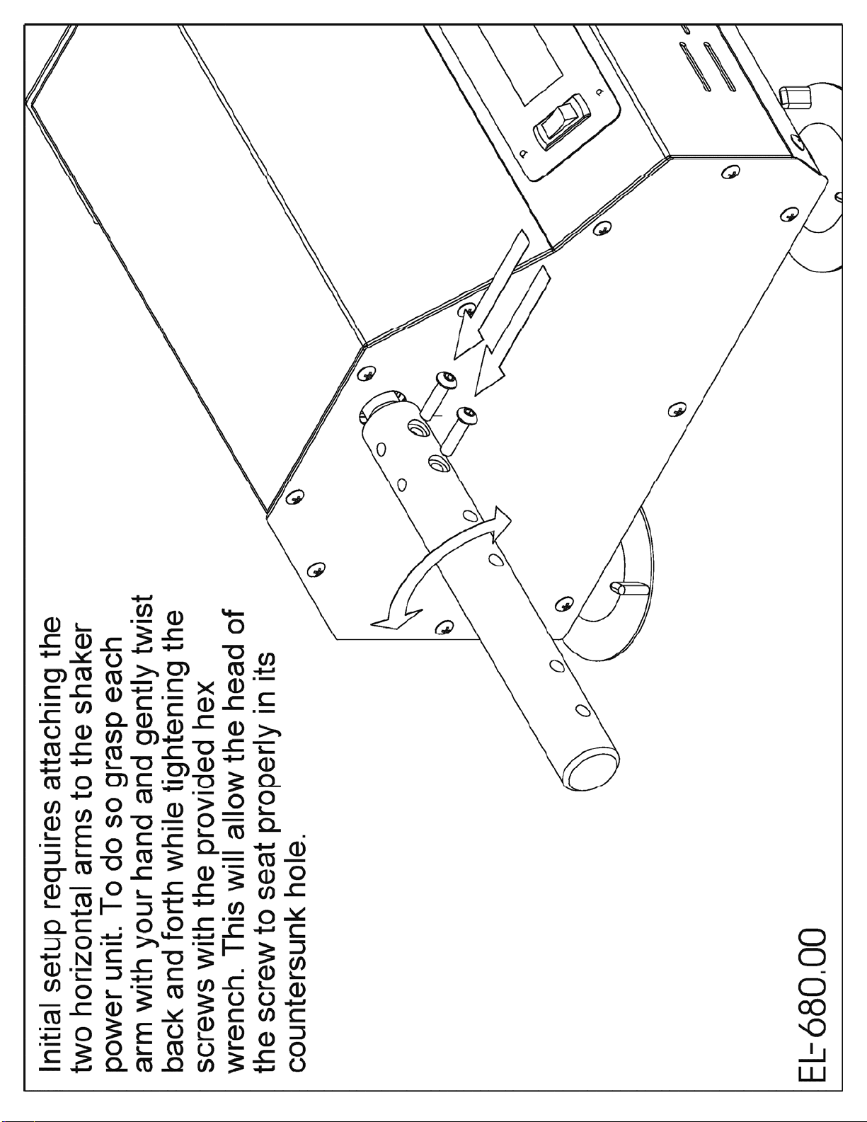
2) Fit the arms with clamps to the shaker side shaft so that the screws
tighten against the flat surface of the shaft.
3BUCAUTION!!! IMPORTANT FOR YOUR SAFTEY
Be sure that the voltage supply is the same as the one indicated on the serial
tag. Operating range is 115V/230V +/- 10%
Do not shake products capable of making an explosive mixture.
Do not use the apparatus if it is not grounded properly.


1) Power Switch
2) Liquid Crystal Display (LCD)
3) Directional Pad (D-Pad)
4) Enter Button
5) Cursor
UOperation:UPress the Power Switch down into the ON position.
The LCD should be lit up showing the main menu. There are three
different run modes to choose from. Select a run mode by moving
the Cursor (using the D-PAD) and press the Enter Button.

Run Mode: When selected the shaker will begin at its lowest speed.
The speed shown in parenthesis (xxxx) is the set speed controlled by
the user. The speed listed to the right is the tachometer read out or
the actual speed of the shaker in real time. The speed can be
increased/decreased by pressing and holding the up/down arrows on
the D-PAD. The longer the button is held down the faster the speed
will increase/decrease. Once engaged the timer will begin counting
all the way up to 999 hours before the timer overflows back to zero.
To pause the shaker move the Cursor to the PAUSE item by
pressing the left arrow on the D-PAD and press the Enter Button.
The clock will pause at its current time and the shaker will gradually
come to a complete stop. The clock and shaker can be resumed at
its current time and speed by selecting RESUME and pressing the
Enter Button. To go back to the main menu move the Cursor to the
EXIT item by pressing the right arrow on the D-PAD and then press
the Enter Button.

Timed Run Mode: The timed run mode features a countdown timer
that automatically shuts the shaker off when the time runs out. When
selected the user will be taken to the Timed Run Setup Menu and will
need to input the run time in hours, minutes, seconds and select the
speed for the run. The left/right arrows on the D-PAD can be used to
move the cursor between hours, minutes or seconds and the up and
down arrows can be used to set the time. The longest run time
allowed is 999:59:59. Once the time is set move the Cursor down by
pressing the right arrow on the D-PAD until the Cursor is next to the
RPM line item. The speed can be set using the up and down arrows
on the D-PAD. Now that the data is set navigate the Cursor to the
START line item using the left/right arrows on the D-PAD and press
the Enter Button.

After selecting START the shaker will begin at the selected speed
and the timer will begin counting down. The speed can be adjusted
in real time using the up/down arrows on the D-PAD. The speed
shown in parenthesis is the target speed controlled by the user and
the speed listed to the right is the actual speed as read by the
tachometer. The shaker and countdown timer can be paused and
resumed. Move the Cursor to the line item PAUSE by pressing the
left arrow on the D-PAD and then press the Enter Button. Exiting
the Timed Run Menu will bring the user back to the Timed Run Setup
Menu.

Speed Run Mode: The speed run allows the user to program in a
set run speed. Once engaged the timer will begin counting all the
way up to 999 hours before the timer overflows back to zero. Select
the speed run mode from the main menu and press the Enter
Button. The user will be prompted with the speed run setup menu.
Set the desired speed using the up/down arrows on the D-PAD. The
left/right arrows can be used to move the Cursor between START
and EXIT. EXIT will take the user back to the main menu. Keep the
Cursor next to the START line item and press the Enter Button.
The user will now be taken to the speed run menu. The shaker will
begin at the speed selected in the setup menu. The speed run menu
behaves in the same way as the run menu with one exception.
Pressing EXIT will not take the user back to the main menu instead
pressing EXIT will take the user back to the speed run setup menu.

Note: All run menus will have two speeds listed. The leftmost speed
will be displayed inside parenthesis. This is the target speed
controlled by the user. The shaker will attempt to match this speed
and should do so within ten seconds after making an adjustment.
The rightmost speed is the tachometer reading, which shows the user
what the shaker is actually running at. The tachometer is accurate
within +/- 1% of actual speed.
Note: Reciprocating shakers will display OSC (oscillations) instead
of RPM (revolutions per minute).
Note: Use slowest speed necessary to produce required shaking
action.
4BMAINTENANCE
CLEANING:
Before removing the casing, disconnect the apparatus from the mains.
The manipulation of the internal electronic circuits of the apparatus by
unauthorized personnel can cause irreparable damage to the apparatus.
When cleaning the plastic, use alcohol with a cotton cloth. When cleaning the
painted metal case, use warm soap and H2O solution.

BELT INSPECTION AND REPLACEMENT:
Inspect belt periodically and replace if actually broken or if the cords are
exposed or frayed. Small outer fabric breaks are not harmful.
Removal of the drive belt may require the adjustment or removal of the motor
and/or the large drive pulley. Installation of a new belt is as follows:
1. Unplug unit to avoid shock and/or electrical component damage.
2. Remove the left side panel to expose the motor and other components.
3. Take note or mark the location of the motor along the adjustable slots in
base plate.
4. Loosen the socket (“allen”) screws that fasten the motor to the base
plate.
5. Slide the motor towards the large pulley to allow the belt to slacken.
6. Remove belt and install new belt with identical number of teeth.
7. Adjust tension on belt. Note: cogged style belt does not need excessive
tension.
FUSE REPLACEMENT:
Replacement fuses for the unit are (2) 3 Amp Slow Blow (Time Delay).
Replace fuses only once. Preventative maintenance has set the fuse to blow
if the motor is over worked. The problem is generally in extreme wear of the
bearings or an object obstructing the shaking action.
NOTE: If replacement fuse blows almost immediately, repairs may be
necessary.
If you have any doubts or inquiries concerning operation contact your supplier or
MRC technical service.

EL-680.00 REPLACEMENT PARTS LIST
PartNo DESCRIPTION QTY.
4112 BEARING 1621-2RS 2
4113 BEARING 1630-2RS 2
4126 BEARING 1200 NSK 1
4127 BEARING 6200ZC3 NTN 1
4259 TIMING BELT 160XL .2"P X 3/8"W NEOPRENE 1
4507 ALUMINUM MOTOR PULLEY 14 GROOVES 1
5528 3.75" SUCTION CUP W/ 5/16-18 THREADED POST 4
5631 3/32 STANDARD ALLEN WRENCH 1
5647 3/16 ALLEN HEX KEY 1
6009 175W POWER SUPPLY 24V/12V RAILS 1
6027.510A 5V VOLTAGE REGULATOR 1
6100 OVERLAY, NO ENCODER 1
6113 FUSE, CYLINDER TIME LAG 3A 2
6278 AC INLET 1
6507.5 ROCKER SWITCH RED ILLUMINATED 1
6649 PLUG 15A/125V TYPE B (115V) 1
6850 DISPLAY BOARD 1
6995.2 100W MOTOR CONTROLER (REPLACEMENT ONLY) 1
6996.500A 100W BRUSHLESS MOTOR 1
7595 #6-32 X 1/4" 18-8 S/S MACHINE SCREW 3
7954 #5-40 X 3/8" FLAT HEAD CAP SCREW 2
8001 #4-40 X 9/32" NYLON BINDING HD SCREW 8
8277 8-32 X 3/8 S/S THSMS 1
8285 #8-32 x 1/4 TRUSS HEAD PHILLIPS 29
8321.5 10-32 x 1/4 SET SCREW KNURLED CUP POINT 8
8554 3/8"-16 X 1" HEX HD. CAP SCREW 4
8586 1/4-20 X 1/2" SOCKET HD CAP SCREW 2
8588.1 1/4-20 X 1" SOCKET HD. CAP SCREW 15
8588.3 1/4-20 X 1.25" SOCKET HD CAP SCREW 5
8589.5 1/4-20 X 2" SOCKET HEAD CAP SCREW 4
9207 #5-40 NYLON-INSERT HEX LOCKNUT 2

9235 #8-32 18-8 S/S MACHINE SCREW NUT 2
9261 1/4-20 ZINC PLATED GRADE 5 STEEL HEX NUT 4
9283 3/8"-24 THINK HEX NUT 2
9435 #12 STEEL WASHER ID 1/4, OD 9/16 2
9531 1/4" ZINC PLATED SPLIT LOCK WASHER 8
9799 4-40 x 5/8" STAND OFF MALE-FEMALE 8
ELP680.202 BAR ARM 1
ELP680.209 MOTOR EXTENTION ADAPTER 1
ELP680.210 BASE WEIGHT 1
ELP680.211 SIDE COLUMNS 2
ELP680.212 PULLEY BLOCK 1
ELP680.213 CRANK BLOCK 1
ELP680.215 CROSS STRAP 1
ELP680.220 BASE PLATE 1
ELP680.223 SIDE PANEL 2
ELP680.240 MOTOR BRACKET 1
ELP680.505A ECCENTRIC SHAFT ASSEMBLY 1
ELP680.507A REAR PANEL ASSEMBLY 1
ELP680.508A CASE ASSEMBLY 1
ELP680.510A FOUR FINGER CLAMP ASSEMBLY 8
ELP680.Q.018 CONNECTING PIN 1
ELP680.Q.200 GEAR 1
ELP680.Q.214 DRIVE CLAMP 1
EP6130.650A WIRING HARNESS ASSEMBLY 1
PLP680.203 RIGHT SHAFT EXTENSION 1
PLP680.204 LEFT SHAFT EXTENSION 1
If you have any questions or inquiries concerning installation or ordering of replacement parts
please contact your supplier or MRC Technical Service @ 972-3-5595252.


(6215)
(6217)
2
BLACK
(6217)
(6278;
FUSES:
(6113)K2
4RED
I'l'l
o
g
o
+
12
DC
OUT
O
POWER
SUPPLY
B
-
1—
(jjpoo
j
1-^
+24
IXJUUT
O
(6995.4)
POWER
CABLE
(6993.3)
I/O
CABLE
S
WHITE
PANEL
GROUNDS
(6215)
(6215)
12
GREEN/YELLOW
13
GREEN/YELLOW
(6215)
(6215)
EBERBACH
CORPORATION
ANN
ARBOR,
Ml
ELECTRICALDIAGRAM
J.B.DRW.
FAB.
ASM.
10/27/14
EL680.605A
Table of contents
Other MRC Paint Sprayer manuals