MRC IncuShaker LOM-7450 User manual

Stackable Incubator Shaker
User's Manual
Please read this user’s manual carefully before using the product.
LOM-7450/7450-CO2/7450-L

Note
1.
2.
3. Preparation
4. Safety Instructions
5. Installation
6. Operational Instructions
7. Structure
8. Control Panel
9. Settings
10. Alarm System
11. Troubleshooting
12. Warranty
13. Packing List
Unpacking Guide
Overview (Features and Specifications)
Please read this manual carefully before installing the equipment. Please follow all
the instructions contained in this manual during operation. Otherwise, the user shall
be responsible for any consequence arising therefrom including potential bodily
harm and/or property damage.
Copyright:
1. No part of this manual may be reproduced, distributed, or transmitted in any form
or by any means, including photocopying, recording, or other electronic or
mechanical methods, without the prior written permission of the publisher, MRC
LTD.
2. Contents contained in this manual, including all technical data, specification, and
performance figures, subject to change without notice.
Preface
Thank you for choosing IncuShaker Series Incubator Shaker. Your trust and support in
MRC LTD. are greatly appreciated.
MRC Incubator Shaker Series is model designed for shaking and heat samples according
to the research and experiment needs in modern biology. State-of-the-art embedded
microprocessor system is utilized in the equipment for its powerful data processing ability,
outstanding stability, excellent interference resistance, and high precision control ability of
the temperature and frequency of the instrument. Sophisticated manufacturing process,
aesthetic product design, and user-friendly interface are elegantly incorporated into the
production of the instrument.
Incubator Shaker is widely used in biology, microbiology, medicine, pharmaceutics, food
science and environmental science, including various biological and chemical reactions
that require high precision control of temperature and frequency, bacteria culture,
fermentation, and hybridization, and enzyme and cell tissue research. It is also applicable
to both static and dynamic culture of microbial cells and strains.
Table of Contents
P7
P8
P9
P11
P12
P13
P14
P22
P24
P26
P27

12
1. Unpacking Guide 1. Unpacking Guide
Note
01. Please contact the manufacturer or your local representative immediately if the
instrument is upside down upon unpacking.
02. Inspect package and contents upon receipt of the instrument. If the instrument is
damaged or if there are any missing accessories according to the packing list, please
contact the manufacturer immediately.
03. Place the instrument on a level and firm surface for use to avoid vibration and noise.
04. Please make sure the power is disconnected and the instrument is not loaded when
moving the instrument. Please move instrument individually before stacking them.
05. When stacking multiple instruments, please make sure the floor load bearing ability is
no less than 1.5 times of the total weight of the instruments. Please place the
instruments beside a wall or on top of a floor with reinforced beam to ensure good
loading condition.
06. Please use the specified fuse and make sure to disconnect power when replacing the
fuse.
07. Please unplug the instrument during maintenance.
08. Do not clean the instrument with corrosive or flammable liquid and make sure this
type of liquid is kept away from the instrument.
09. Please use a power supply specified on the nameplate on the right side of the
instrument.
10. The maximum load of an individual unit is 15 kg. When three units are stacked, the
maximum speed is 250 rpm for the top unit and 300 rpm for the middle. When the
instruments are running with the maximum load, it is recommended to set the
rotation speed no more than 250 rpm.
11. Please make sure the vent of the instrument is kept away from other vents or heat
sources. Otherwise, the compressor may not be able to start normally or start
frequently during the cooling process.
12. Please make sure the gas supply type is in accordance with the requirements and
all the pipes are correctly and firmly connected. Please set the gas pressure as
specified. Any wrong pipe connection or inappropriate air pressure settings may
cause a CO2 gas leak. High CO2 concentration may harm your health and
potentially lead to suffocation or death.
13. Please ensure sufficient ventilation when using CO2. CO2 concentration will
increase in a small confined room and high CO2 concentration is harmful to health.
In addition, please avoid direct inhaling of CO2 when opening the compartment door
of the product.
14. Please place the 4 small footings of the instrument on
top of the 4 big fixed footings when stacking multiple
units.
Lifting the instrument by hand should be prohibited. Please use a lift or a forklift or other
lifting apparatus to raise or move the instrument.
Warning
Unpacking Procedures
1. Place the instrument on a level surface with caution. Remove the packing material and
inspect if the instrument is damaged.
2. Please find the packing list, in the user manual, in the plastic documents pouch inside
the packing box.
3. Check the packing list in the manual make sure there are no missing accessories.
Otherwise, please contact the manufacturer immediately.
push
step 1
step 2
step 3
step 1
step 2
step 3

3
2.1 Description
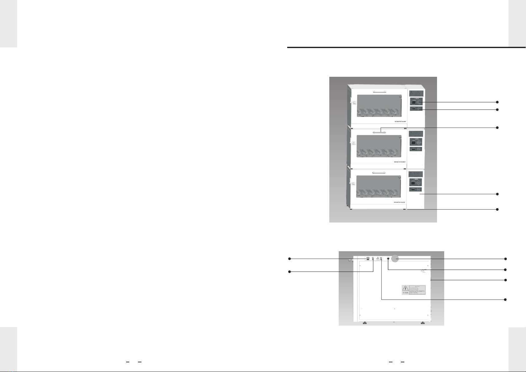
LOM-7450 are a stackable incubator shaker models with cooling function. The instrument
can be used individually or stacked on top of each other to save floor space. Flip-down
door style allows independent operations of stacked instruments, which makes batch
treatment of samples easy. The triple-eccentric counterbalanced drive, with a
circumferential oscillation diameter of 2.6 centimeters, provides dependable and durable
operation of the instrument. Speed terminal feedback system guarantees high precision
oscillation within the speed range of 30 to 300 rpm. Innovatively combined PID and fuzzy
control technique makes into reality less than 0.1 °C temperature fluctuation within 4 °C to
60 °C range. LOM-7450-CO2 are a stackable incubator shaker model equipped with a
CO2 incubator. It is configured with accurate CO2 and humidity monitoring system that
ensures stable pH level for high-efficiency cell culture.
LOM-7450-L are a stackable incubator shaker model that provides 9 levels of lighting
which meets most needs of plant, seed, microbial, and viral cell culture.
The instrument can be operated under continuous or 0 to 999 hours timed mode. Up to 6
segments of parameters' programming automates environmental condition moderations
and treatment time change for the same sample.
Sliding rail structure of the shaking platform makes sample operations convenient. Large
chamber size accepts flasks up to 5 liters.
2. Overview 2. Overview
2.2 Features
● Large view window
● LCD dot-matrix display
● User-friendly interface
● Multi-segment programming
● Extra long timing up to 999
hours
● Soft start and smooth
acceleration
● Open door cut-off switch
● Sliding rail design of the
shaking platform
● Open door light-on switch
● Automatic adjustment of
PID parameters
● Drainage groove
● Multiple safety features
● Stackable instrument
● Automatic defrost
Minimizes the need to open the lid.
Displays settings and measurements.
Enables intuitive control panel and menu
selections.
Automates operation under different sample
treatment needs.
LCD displays remaining time, end-of-study sound
and light alarm.
Soft start technique guarantees smooth acceleration
and prevents samples from spilling.
Stops motion when opening the chamber door to
protect users from potential accidental injury.
Convenient replacement of clamps.
Lamp is automatically turned on when opening the
door to help user handle various operations.
Note: The lighting switch is deactivated when the
chamber door is open; The lamp will always be on.
PID parameters are automatically adjusted
according to different conditions.
Built-in drainage groove makes it easy for getting
the liquid outside of the chamber when cleaning the
instrument.
Safety lock control, refridgerator overload protection,
overtemperature protection, overtemperature alarm,
thermal runaway protection, sensor malfunction
alarm, and automatic shut-down system when
malfunctioning ensures safe operation.
Saves floor space.
Automatically defrosts the evaporator in the
refrigerator; no need to manually defrost the frost
buildup. Temperature rise is less than 1.5 °C during
defrosting.
4

3000
6000
9000
11000
13000
16000
18000
20000
500ml×18 clamps
<1100W
AC220V±22V 50Hz±1Hz
1240mm×777mm×670mm
220kg(single unit)
0-20%
0.1%
Infrared
≤95%
0-20000LX
9 Levels
56
2. Overview
2.3 Specifications
LOM-7450 LOM-7450-CO2 LOM-7450-L
4℃~60℃
±0.3℃(37℃)
0rpm, 30rpm~300rpm
±1 rpm
Φ26mm
6
0999h~
740 500mm×
1
50ml×90/250ml×30/500ml×18/
1000ml×12/500ml×6
Model
Temperature
Settings Range
Temperature
Control Range
Environmental Condition
Temperature
Control Precision
Temperature uniformity
Rotation Speed
Speed Precision
Oscillation Range
Program Segments
Timer Range
Platform Size
Platform Number
Maximum Capacity
Standard Configuration
Power
Power Supply
Overall Size
Net Weight
CO2
Concentration Rang
CO2
Concentration Precision
CO2 Detecting sensor
Chamber Humidity
Illuminance
Control Range
Illuminance
Control Levels
Ambient temperature minus 15 °C to 60 °C (lowest 4 °C)
Temperature Humidity10℃~35℃ 20~80%RH
0.1 °C (in constant temperature state)
-
-
-
-
-
-
-
-
-
-
-
-
2. Overview
Illuminance Levels for models with lighting function:
Illuminance Level Illuminance (Lx)
Natural Light in Chamber
0
1
2
3
4
5
6
7
8
Remark: Listed temperature control range and uniformity are measured when the
lighting function is off for model LOM-7450-L. The lighting function of the model
may affect the temperature uniformity and cooling effectiveness.

●
or other lifting apparatus to raise or move the instrument.
● The CO2 concentration may increase and do harm to your health if using the
instrument in a small confined room.
Please ensure sufficient ventilation when using the instrument with CO2 function on.
The gas concentration will increase in a small confined room and high concentration
of CO2 is dangerous for human health. Additionally, please avoid direct inhalation of
the CO2 gas when opening the chamber door.
Lifting the instrument by hand should be prohibited. Please use a lift or a forklift
78
3. Preparation
The instrument must be placed on a firm and level surface. The total weight of the
instrument when fully loaded must be taken into consideration. There must be suffient
space left around the instrument. It should be at least 50 cm between the instrument
and the wall or any two adjacent instruments.
3.1 Placement Conditions
Warning
3.2 Ambient Conditions
a. Environmental temperature condition:
b. Humidity condition:
10℃~35℃
20~80% RH
3.3 Space Conditions
a. Instrument size with door closed(W X D X H):
b. Instrument size with door open(W X D X H):
c. Overal size when stacking three units(W X D X H):
124×78×67cm
124×132×67cm
124×78×200cm
Please leave adequate space around the instrument to help the cooling system of the
instrument to dissipate heat and future maintenance. It should be at least 50cm between
the instrument and the wall or any two adjacent instruments.
3.4 Power Supply Conditions
Please use the power supply voltage as listed on the nameplate at the right side of the
instrument.
4. Safety Instructions
Lifting the instrument by hand should be prohibited. Please use a lift or a forklift or other
lifting apparatus to raise or move the instrument.
● Make sure whether the local power supply voltage is suitable for use.
● The instrument must be properly grounded.
● Use independent power supply.
● Do not use extended power cord.
● Do not drag the power cord when unplugging.
● Do not use non-specified nor damaged power cord.
● Only professional personnel are allowed to open the power box.
● Tighten the fixing handle on the aluminium platform.
● Ensure good ventilation of the room.
●
Please make sure to follow the safety instructions!
The power supply must be unplugged under any of the situations below:
When moving the instrument
When opening the power box
When changing the fuses
When the instrument is malfunctioning
When the instrument is not in use
●
●
●
●
●

PU Pipe
outer dia. 10mm)
(Inner dia.7mm,
Warning
910
5. Installation 5. Installation
Lifting the instrument by hand should be prohibited. Please use a lift or a forklift or other
lifting apparatus to raise or move the instrument.
Note
Note
5.1 Tools Requirment
a. 2 adjustable wrenches
b. 2 cross screwdriver
c. 1 spirit level
d. 1 lift or forklift or other lifting apparatus with the minimum
loading to be 250 kg
5.2 Installation
a. Place the instrument on the ground as
instructed in Chapter 3.1;
b. Adjust footings: as shown in the figure,
1 of the 4 footings is adjustable.
c. Repeat step b to stack instruments.
Footing Adjustment Method:
1.After stacking the the instrument, turn the hexagon nut down using the wrench to loosen.
2.Insert the screwdrive into the adjustment hole and turn the footing. After the instrument the
leveled (the 4 footings are at the same level), turn the hexagon nut up to tighten.
Please make sure each instrument is level and not shaking when stacking multiple of them.
It is forbidden to load the instrument more than 15 kg of the maximum load. It is for bidden
to exceed the maximum speed, especially for instruments at the 2nd and 3rd levels.
Connect CO2 gas tank
1. Install a regulator with flow control valve onto the gas tank (see optional accessories
2
table). Please choose a regulator with the primary preset pressure to be 25 MPa (250kg/cm .
22
3500l b/in ), and secondary preset pressure to be 0.6 MPa (2.0kg/cm ,30psiG).
2. Using the provided pipe to connect the regulator
with the instrument. The gas inlet port is
positioned at the right side of the instrument
(as shown in figure 1).
3. Adjust the secondary flow control valve to point the pointer to 0.1
– 0.2MPa (as shown in figure 2). It may cause the pipe connect the
incubator and the inlet port to fall off and the leak of the CO2 gas if the
secondary pressure is too high. High CO2 concentration will do harm
to your health and may cause suffocating and death. Maintenance is
required if the inner pipe falls off.
4. Check if there is leak at the connections (pipe with regulator, pipe with
inlet port of the instrument, and pipe with filter).
5. Connection components
A. Schematic diagram B. Actual picture
Gas Inlet
PU Pipe
Filter
Protection Cover
Figure 1
Figure 2
To the filter
Stainless steel hoop
To the CO2 regulator
Note:
1. Do not turn the pressure adjustment rod on the regulator when changing the gas tank.
It will change the secondary pressure if the pressure adjustment rod is turned and more
adjustment will be needed. It may cause the pipe connect the incubator and the inlet port
to fall off. Maintenance is required if the inner pipe falls off.
2. Inspect the conncection of the pipe regularly to ensure it is safely connected. If the pipe
is damaged or aged, change pipe.
3. Use the stainless steel hoop to tighten the connection point of the PU pipe and the filter
to prevent the pipe from falling off and leakage of gas.
4. The CO2 gas purity is more than 99.99%. Low gas purity may cause blocking of the
filter or damage of the electromagnetic valve.
Make sure the gas supply meets the specified requirements. Make sure all the
pipes are properly connected. Make sure the gas pressure settings are correct.
Wrong pipe connection or pressure settings may cause CO2 leakage. High CO2
concentration will do harm to your health and may cause suffocation and death.
Alternative methods should be taken if there is no sufficient ventilation in the
room to guarantee safety. These methods include gas monitoring and alarming
system. Maintain correct gas pressure can prevent gas leakage.
Hexagon Nut

●Product Front View
●Product Side View
11 12
6. Operational Instruction
●
heat dissipation outlet and direct sunshine should be avoided.
● Adjust the instrument footings to level the instrument and make sure the instrument
can operate smoothly.
● Please make sure the instrument is placed at lease 50 cm away from the wall and
other objects.
● Please use a dedicated power outlet with a capacity no less than 1.3 kW and AC 220 V.
● It is not allowed to use gasoline, banana oil, and any other volatile chemicals to contact
with the outside coating of the instrument.
● No experiment samples are allowed in the control panel.
● No excessive force should be used when opening and closing the incubator door to
prevent the instrument from being damaged.
● Please reduce the times of opening the incubator door to help maintain constant
temperature and save CO2.
● After the instrument cooling function is used for 10 days continuously, a heating
dehumidification process is recommended. Recommendation: heat the instrument to
45 °C and last for half an hour.
● Inspect the fastening screws on the flask clamp regularly to prevent it from falling off.
● Please clean the instrument regularly.
● Please check if the v-belt at the bottom of the instrument is not loosened after using the
instrument for 6-12 months. Press the middle part of the v-belt inward about 10 mm.
Please check the abrasion condition of the v-belt after using the instrument for 2 years
and change the same type of v-belt (Z1000) if necessary.
● Please disassembly the side plate at the right and back of the instrument to clean out
dust on the condenser and fan to ensure good heat dissipation and high cooling
efficiency.
● Dehumidification is required if the humidity of the instrument is too high.
● Ensure good ventilation of the room.
● Please make sure the air circulation is sufficient when using CO2. The CO2
concentration will increase in a small confined room and do harm to your health. Also,
please avoid direct inhalation of the CO2 gas when opening the the incubator door.
The instrument should be palced in a clean and dry environment. Any heat source or
7. Structure
Temperature and
speed control panel
CO2 control panel
Handle
Ventilation hole
Adjustable footings
Infrared lamp switch
Power switch
Fluorescent lamp
switch
Filter
CO2 switch
Power inlet

Indicator Light: red light indicates alarm is on; green light indicates the heating or cooling
function is on.
13 14
8. Control Panel
E : Press the button to confirm your current settings.
F : Press the button to start the instrument when it's in “Simple Operation” mode.
A :Press the button to enter the settings menu when in “Simple Operation” or
“Timing Program” modes.
B : Press the button to move the flashing cursor to the right when setting multiple
digits. When the cursor is at the right most digit, press the button to move it to the
first digit.
: Press the button to move the flashing cursor to the left when setting
multiple digits. When the cursor is at the first digit, pres the button to move it to the
last digit.
C : Press the button to move the cursor down. If the cursor is at the bottom line,
press the button to move it to the top.
D : Press the button to change the settings (for example, “YES/NO”, “ON/OFF”, or
number 0 to 9).
: Press the button to change the settings (for example, “YES/NO”, “ON/OFF”, or
number 0 to 9. Long press the button can change value continuously).
G : Press the button to stop the instrument when it's in “Simple Operation or Timing/
Program” mode.
9. Settings
Turn on the power switch at the right side of the instrument after the instrument is properly
placed. “Thanks for choosing MRC LTD. products” will be shown on the display window.
The function selection menu will be displayed after 2 seconds.
Press “ ” button to choose the operation and press “ ” to confirm.
A. Simple Operation
Choose “Simple Operation” on the Main Menu and press the “ ” button to confirm.
The display window will then show the Simple Operation Settings menu.
(For models with illuminating function)
(for models with illuminance function)
Press “ ” button to choose the parameter that needs to be modified; press “ ” or
“ ” button to move the cursor to the digit that needs to be modified and press “ ”
or “ ” button to modified the current number; Press “ ” button when the cursor is at
back to main interface to return to the main interface. Press the “ ” button (wherever
the cursor is) to enter “Smple Operation” page.
Simple Operation
Timing/Program
Main Set
Temp.:37.0℃
Speed:100 rpm
Time:000:00:00
Main Interface
Temp.:37.0℃
Speed:100 rpm
Time:000:00:00
Stop and Return
Temp.:37.0℃
Speed:100 rpm
Light Strength:
Time:000:00:00
Main Interface
1
Temp.:37.0℃
Speed:100 rpm
Light Strength:
Time:000:00:00
Stop and Return
1
...

15 16
9. Settings9. Settings
When the cursor is at “Stop and Return”
Press the “ ” button to stop the operation and return to the main interface.
Press the “ ” button, the instrument will stay in normal operation and enter the “Simple
Operation Settings” page.
Press the “ ” button to stop the instrument and enter the Simple Operation Settings page.
Set
Continue Run
Main Interface
Press the “ ” button to choose the function according to the page displayed and press
the “ ” button to enter the corresponding page.
B.Time/Program Controlled Operation
Choose the “Timing/Program” at the function selection menu and press the “ ” button
to enter the Time/Program Controlled Operation page.
Run as Program
Programming
Main
Press the “ ” button to choose the function according to the page displayed and pree
the “ ” button to enter the corresponding page.
1. The instrument will run with the previously entered program if choosing the “run current
program”. Enter “Timing/Program” page.
(for models with illuminance function)
The instrument will enter the next segment of program to run.
The buzzer will sound 5 times after finishing running the program. Return to “Timing/
Program” page.
When “Timing/Program Operation” shows on the display window, press the “ ” button
to choose whether to continue running.
Stoppig?
Y/N
Press the “ ” or “ ” button to choose “YES/NO” and press the “ ” button to
enter the next page.
When “Timing/Program Operation” shows on the display window, press the “ ” button
to enter the editing page of the current program.
NO.1 Total: 4
Temp.:
Speed:
TimeUp:
37.0℃
100rpm
002:00:00
NO.1 Total: 4
Temp.: 37.0
Speed: 100rpm
Light Strength: 1
TimeUp: 002:00:00
℃
Press the “ ” button to choose the parameter needs to be modified; press the “ ” or
“ ” button to move the cursor to the digit that needs to be modified and press the “ ”
or “ ” button to modify the current value; press the “ ” button to enter the next
programming page. After the last segment of program is edited, press the “ ” or “ ”
button to choose “YES/NO” according to the message displayed and press the “ ”
button to enter the next page.
Saving?
Y/N
(for models with illuminance function)
Temp.:37.0℃
Speed:100 rpm
TimeUp:002:00:00
NO.1 Total: 4
Temp.:37.0℃
Speed:100 rpm
TimeUp:002:00:00
NO.1 Total: 4
Temp.:37.0℃
Speed:100 rpm
TimeUp:002:00:00
Light Strength: 1
NO.1 Total: 4
Temp.:37.0℃
Speed:100 rpm
Light Strength
TimeUp:002:00:00
: 1
NO.1 Total: 4
.
.
.
.
.
.

17 18
9. Settings9. Settings
2. Choose “Programming” to enter the program page.
Set Programs:
Total(1-6): 4
Main Interface
Press the “ ” and “ ” button to modify the number of program segments nad pres
the “ ” button to enter the program page.
Press the “ ” button to choose the parameter that needs to be modified; press the
“ ” or “ ” buton to move the cursor to the digit that needs to be modified and press
the “ ” or “ ” botton to modify the current value; press the “ ” button to enter to
the next program segment. After the last segment is edited, pres the “ ” or “ ” button
to choose “Y/N” according to the message displayed and press the “ ” button to
enter the next page.
Saving?
Y/N
C.Instrument Settings
Choose “Main Set” on the main pageand press the “ ” button to enter.
Basic setting
Com. Addr. Set
Temp. Setting
Main Interface
Press the “ ” button to choose a function and enter the “ ” button to enter the
corresponding operation page.
a) Basic settings
Press the “ ” button to choose the parameter that needs to be modified; press the “ ”
or “ ” button to choose “OFF/ON” and press the “ ” button to save the parameter
setting and return to the “Main Set” page.
b) Contact information settings
Press the “ ”or “ button to choose the parameter that needs to be
modified; press the “ ” or “ ” button to change the number (contact
information settings is effective only in multi-instrument network) and press
the “ ” button to save the parameter settings and return to the “Main
Set” page.
”
c)Temperature control parameters settings by choose Temp. Setting.
(for models with illuminance function)
NO.1 Total: 4
Temp.:
Speed:
TimeUp:
37.0℃
100rpm
002:00:00
NO.1 Total: 4
Temp.: 37.0
Speed: 100rpm
Light Strength: 1
TimeUp: 002:00:00
℃
Speeding Alarm:
Overheat Alarm:
ON/OFF
ON/OFF
Set Password:
XXXX
Return Main Set
Set Com. Addr.:
XX(0-32)

T1: 37.0℃ (+0.0 )
T2: 37.0℃ (+0.0 )
T3: 37.0℃ (+0.0 )
T4: 37.0℃ (+0.0 )
A: 04.0℃ (00.0)
B: 10.0℃ (00.0)
C: 20.0℃ (00.0)
D: 37.0℃ (00.0)
19 20
9. Settings9. Settings
Press the “ ” button to choose the parameter that needs to be modified or “Main
Interface”; press the “ ” or “ ” button to move the cursor to the digit that needs to
be modified and press the “ ” or “ ” button to change the value; press the “ ”
button to enter the password and enter the “password setting” page if the password
enterted is correct; press the “ ” button to enter password and enter the auto adjust the
temp. parameters page if the password entered is correct.
Note: In order to prevent misoperation, the manufacturer will keep the original password.
If the password is lost, please contact the customer service department of the
manufacturer immediately.
C.1 Password Setting Page
Press the “ ” button to choose the parameter that needs to be modified or “Main
Interface”; press the “ ” or “ ” button to move the cursor to the digit that needs to
be modified and pres the “ ” or “ ” button to change the calue; press the “ ”
button to save the password and return to the instrument settings page (the password is
not saved if the cursor is at back to the instrument settings).
C.2 Temperature Control Parameters Settings
Temp. Display
Temp. Calibrate
Temp. Setting
Return Main Set
C.2.1 Temperature Display
Press the “ ” button to choose the parameter that needs to be modified; press the
“ ” or “ ” button to move the cursor to the digit that needs to be modified and press
the “ ” or “ ” button to modify the value (-5 to 4, resets at -5); press the “ ” button
to save the current parameters and return to the temperature control parameter settings
C.2.2 Temperature Calibration
The value outside of the bracket is the target temperature value, the value inside the
bracket is the difference between the actual temperature and the target temperature; the
emperature values of A, B, C, D, E, F listed in the small to large order are (04.0, 10.0, 20.0,
37.0, 50.0, 60.0). Press the “ ” button to choose the parameter that needs to be
modified; press the “ ” or “ ” button to move the cursor to the digit that needs to be
modified and press the “ ” or “ ” button to change the current value (-9 to +9); press
the “ ” button to save the current parameter settings and return to the temperature
control parameter settings page.
C.2.3 Temperature Settings
It will enter the next page after 2 seconds or if pressing the “ ” button.
Press the “ ” button to exit the temperature control parameters settings.
Choose the temperature control parameter settings to enter the corresponding
settings. The whole process takes about 2 hourse. During this process, the power
should not be cut off and the incubator door is not allowed to be opened. Otherwise
page; T1, T2, T3, T4 are the current temperature values of the 4 temperature sensors
inside the incubator, the value in the bracket is the temperature difference between the
sensor value and the precise temperature detector value; (for example: T1: 37 °C, means
the temperature sensor shows the temperature inside the incubator, if the precise
temperature detector at the same spot of the sensor shows the temperature to be 36 °C,
-1.0 will be shown in the bracket, ie (-1.0)).
Set Password:
XXXX
Return Main Set
Temp.is
auto adjusting
Don’t touch the
pad. About 2hours
Temp.
is Auto Adjusting
Please hold on
parameters

CO2:05.0%
00.0%Calibrated Value:
21 22
9. Settings
the temperature parameters may be inaccurate and other unpredictable problems
such as inprecise temperature control or temperature out of control may occur
during normal operation.
d) CO2 Settings
Press the “ ” button and enter the CO2 concentration settings. Press the “ ” button
to move the cursor to the digit that needs to be modified and press the “ ” or “ ”
button to change the current value. Press the “ ” button after the settings are finished.
e) CO2 Calibration
During normal operation, press the “ ” button first and then the “ ” button to enter
the CO2 concentration calibration mode. The first line shown on the display window is the
current CO2 concentration the sensor measures and the second line is the target value.
Press the “ ” , “ ”, and “ ” buttons to adjust the target value. Press the “ ”
button again and then the “ ” to enter normal operation. The calibrated value is saved
and the CO2 calibration is now successful. If press the “ ” button in the calibration
mode, the instrument will exit the CO2 concentration calibration mode, the calibrated value
are not saved.If press the “ ” button in the calibration mode, the instrument will exit the
CO2 calibration and the target value is not saved and reset to factory settings.
The instrument will exit the CO2 calibration automatically if there is no operation in 10
seconds in the CO2 calibration mode and the target value is not saved.
f) Illuminance Setting
During the normal operation, press the “ ” button when “Light Strength: X ” is shown on
the display window to make the cursor flashing at the X point. Press the “ ” and “ ”
buttons to choose the required level and the illuminance setting is finished.
Temp.:
Speed:
Light Strength: X
TimeUp:
Main Interface
37.0℃
100rpm
000:00:00
10. Alarm System
Alarm prompt:
● Overspeed alarm interface
Speeding Alarm
Stop and Return
Stop and Return
Stop and Return
The “Overspeed Alarm” line will keep flashing, the buzz will sound intermittently,
and the instrument will stop running.
● Overtemperature alarm interface
Overheat Alarm
The “Overtemperature Alarm” line will keep flashing, the buzz will sound intermittently,
and the instrument will stop running.
● Communication Failure Alarm Interface
Com. Fault Alarm
The “Communication Failure Alarm” line will keep flashing.
●
The buzz will sound every 2 minutes.
Door Open Alarm

No Inject
Humidity:50%
CO2: 06.0%
50%Humidity:
CO2: 03.0%
:50%Humidity
LCD Display Sound
Overspeed
alarm
Communication
failure
Cause Solution
23 24
10. Alarm System
●
value)
CO2 concentration high alarm (when the CO2 concentration is 1% higher than the set
Alarm indicator light will flash and the buzz will sound. Press any key to stop the buzz but
the alarm indicator light will remain flashing.
●
for no less than 15 minutes)
CO2 concentration low alarm (when the CO2 concentration is 1% lower than the set value
Alarm indicator light will flash and the buzz will sound. Press any key to stop the buzz but
the alarm indicator light will remain flashing.
No gas intake alarm●
The no gas intake alarm will show on the display window if the instrument remains in the
CO2 concentration low status for more than 5 minutes. The alarm indicator light will flash
and the buzz will sound. The electromagnetic gas valve will be closed automatically.
Press any key to cancel the alarm status and the instrument will stop operation.
11. Troubleshooting
Troubleshooting
Error
Intermittent-
siren
Intermittent-
siren
Intermittent-
siren
Intermittent-
siren
Over-
temperature
alarm
No gas intake
Speed difference more than 5 rpm
Electrical malfunction
Electric motor failure
Temperature difference more than
3 degrees
Temperature sensor damaged
Cooling system failure
Heating system malfunction
Communication cable not connected
Communication cable interrupted
Door open
Sensor damaged
Empty CO2 gas tank
Contact local sales/service
Change sensor
Connect communication cable
Restart instrument
Close incubator door
Change sensor
Change CO2 gas tank

Instructions
Display window
off Platform not
shaking
Platform shaking
but the display
window
malfunctioning
Display window on
but platform not
shaking
High temperature
fluctuation
Loud noise
No power
Burned fuse
High frequency
interference source
exists in the same
ower line
Poor contact of door
switch
Frequent door opening
Unleveled instrument
Loose platform
Loose flask clamp
Plug not connected
Power outlet out of power
Power switch off
Change to a new fuse with the same specification
Position: at the powr
outlet
Position: inside the
electrical cabinet
Remove interference source of the same power
line or use a dedicated power line
Press the confirm button to recover display
Contact local sales/service
Reduce times of door opening and decrease
the time consumed when opening the door
Adjust footings to level the instrument
Fasten the fixing screws of the platform
Fasten the fixing screws of the flask clamp
11. Troubleshooting
25 26
Code
Customer tel.: 972-3-5595252

40 × ø16 mm
AC250V/10A
1
1
1
1
1
2
1
1
1
1
1
1
4
1
1
27
Packing List
Name Qty Note
Stackable Incubator Shaker
Accessories
Power Cord
Liquid Collection Tray
Fuse
Cross Screwdriver
M8 Star Nut
User Manual
Certificate
Wrench
Filter
Filter Protection Package
Gas Pressure Regulator
Stainless Steel Hood
PU Pipe (5 m)
Alluminium Foil
Platform handle backup
For Model LOM-7450-CO2 only
Optional Accessories
Name Specifications Name Specifications
50ml
100ml
150ml
200ml
250ml
500m
1000ml
2000ml
3000ml
5000ml
96
800×500
5000ml
Flask Clamp
Flask Clamp
Flask Clamp
Flask Clamp
Flask Clamp
Flask Clamp
Flask Clamp
Flask Clamp
Flask Clamp
Flask Clamp
Flask Clamp
Test Tube Rack
Test Tube Rack
96-Well Microplate
Holder
40 ø14 mm×
Multifunction Spring
Frame
Adjustable Test Tube
Clamp Component
Conical Flask Clamp
Aiuminum Foil
This manual suits for next models
2
Table of contents
Other MRC Paint Sprayer manuals