MRF TB8X21 User manual

OPERATOR’S MANUAL
TELESCOPING BOOM
Model TB8X21
Serial Number 14592-
Manual# 96337 AUG 2020 ENGLISH
COPYRIGHT © 2020
MESSER REPAIR AND FABRICATING, LLC
SAUK CENTRE, MN
PRINTED IN USA
ALL RIGHTS RESERVED

2
Using This Manual
The term loader is used in this manual to refer to a skid
steer loader.
Your loader operator’s manual contains instructions to
safely operate the loader. Anyone who operates a loader
with this attachment installed must rst read, under-
stand and follow the instructions in the loader operator’s
manual.
This manual contains instructions to safely operate and
service the attachment. Anyone who operates or services
the attachment must rst read, understand and follow the
instructions in this manual.
Additional operating or servicing information for the
attachment may be provided online, in video, or in
other publications. This additional information does not
replace, and is not a substitute for reading and following,
the instructions in this manual.
The safety alert symbol is shown in WARNING state-
ments to alert users to hazards which could cause death
or injury. Carefully read and follow the messages.
IMPORTANT notices alert users to instructions which, if
not followed, could result in damage. Carefully read and
follow the messages.
There may be times when the attachment and loader
shown in this manual may not be your exact model. The
model shown will be close enough to your attachment or
loader to accurately convey the information.
The most current information available is included in
this manual. The publisher may revise this manual at any
time and is not required to notify users of revisions.
Replacement Manuals
Be sure to include this operator’s manual if you sell or
transfer ownership of the attachment.
Contact Messer Repair and Fabricating, LLC for a
printed manual, or nd a downloadable manual on our
website.
Using This Aachment
The attachment is designed with three telescoping sec-
tions. It is designed for installation of secondary attach-
ments designed by the manufacturer on the end of the
telescoping sections.
The attachment is designed for installation on a full-size
loader, connected to the loader’s front auxiliary hydrau-
lic couplers.
The manufacturer reserves the right to make improve-
ments, and to discontinue or change specications,
models or design without notice and without incurring
obligation.
Loader Compability
Conrm your loader’s Rated Operating Capacity in the
loader operator’s manual. Do not install the attachment
on the loader if it will exceed the Rated Operating Ca-
pacity during operation because this may cause diculty
in controlling the loader or may cause loader damage.
The attachment is designed for use on loaders with a
Rated Operating Capacity of more than 2000 lbs, but not
to exceed 4000 lbs.
Product Misuse
Product misuse can cause accidents, injury and death.
The manufacturer of the attachment is not responsible
for any harm or injury resulting from product misuse.
Product misuse includes operating or servicing the at-
tachment without following the instructions in this man-
ual, using the attachment in any way for which it was not
designed, and modifying the attachment.
Modicaons
Do not modify the attachment in any way.
Manufacturer Contact
Call Messer Repair and Fabricating, LLC at (833) 352-
3477, or visit www.messerrepair.com.
Introducon

3
SpecicaonsIdencaon Numbers
Record your product information to provide when you
contact the dealer or manufacturer.
Telescoping Boom
Model TB8X21
Serial Number 14592-
Serial Number Locaon
Purchase Date
Dealer
Dealer Phone
Model
Serial #
Product Idencaon and Specicaons
Model TB8X21
Overall Width x Height 1.2 x 0.5 m
(46 x 22 in.)
Overall Length (Collapsed) 2.4 m (96 in.)
Overall Length (Extended) 6.5 m (255 in.)
Cylinders 2 x 48 in.
3500 PSI
Weight 295 kg (650 lb.)

4
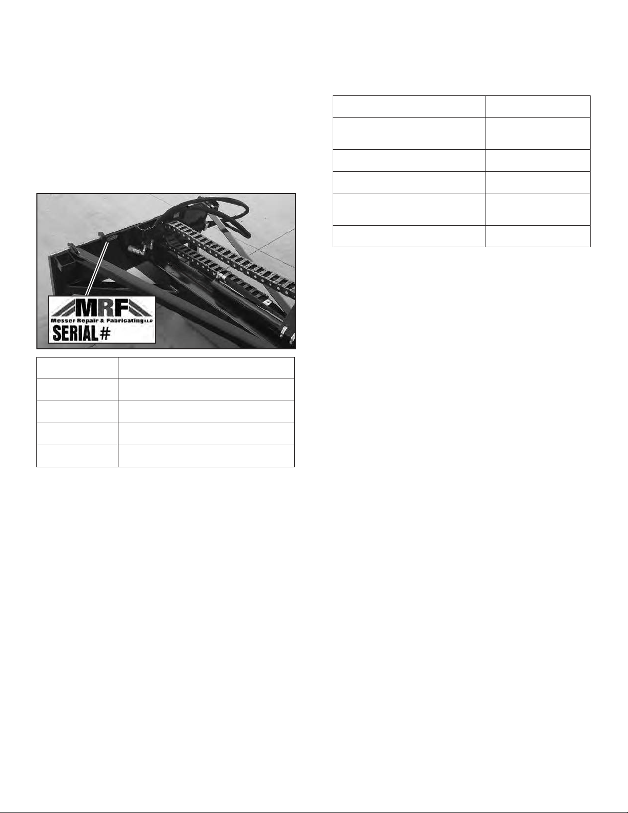
Locaon Descripon Part Number
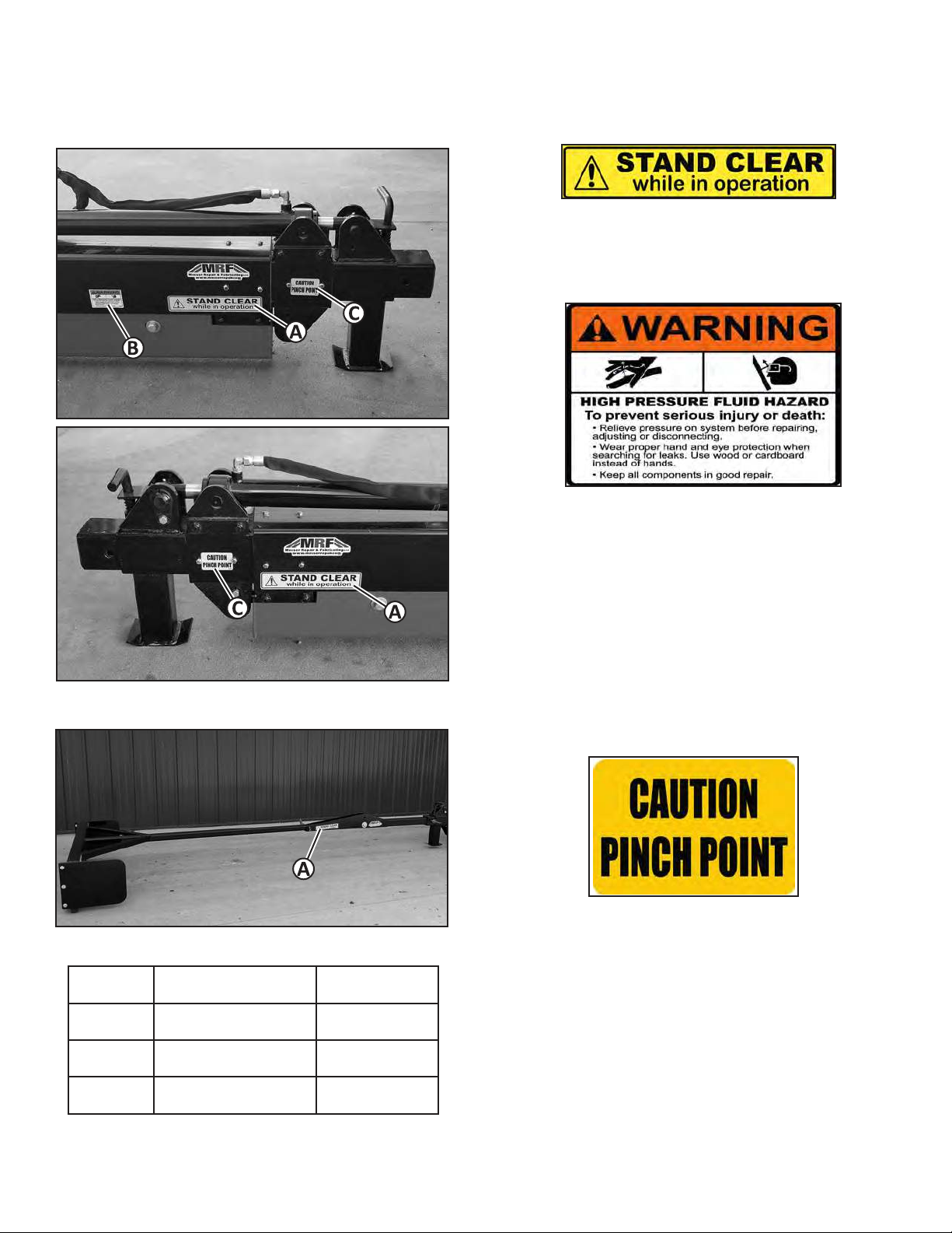
A Stand Clear Decal 96028
B Warning Decal 96117
C Caution Decal 96109
Safety Decals
Decal Locaons (Telescoping Boom) STAND CLEAR DECAL 96028
STAND CLEAR WHILE IN OPERATION
WARNING DECAL 96117
HIGH PRESSURE FLUID HAZARD
To prevent serious injury or death:
• Relieve pressure on system before repairing, adjust-
ing or disconnecng.
• Wear proper hand and eye protecon when search-
ing for leaks. Use wood or cardboard instead of
hands.
• Keep all components in good repair.
CAUTION DECAL 96109
PINCH POINT
Decal Locaons (Oponal Roof Rake)

5
Wear Protecve Equipment
• Wear gloves to protect hands from burns if hydraulic
couplers become hot during operation.
• Never wear sandals or other light footwear when op-
erating or servicing the attachment. Wear protective
footwear when handling blades or heavy parts.
• Do not wear loose tting clothing which may
become entangled when operating or servicing the
attachment.
Parking Safely
1. Follow the instructions in the loader operator’s man-
ual to park the loader safely.
2. Fully collapse the boom.
3. Fully lower the attachment to level ground.
4. Stop the loader engine and remove the key from the
switch.
5. Do not leave the loader operator seat until the engine
and all other moving loader and attachment parts
have stopped.
6. Follow the instructions in the loader operator’s man-
ual to exit the loader safely. Use the attachment step
area if one is provided.
Operang Safely
• Do not allow anyone to operate the attachment
unless they have rst read and understood the loader
and the attachment operator’s manuals.
• Do not allow anyone to operate the attachment
unless they have rst read and understood the safety
and warning decals on the loader and on the attach-
ment.
• The attachment owner is responsible for training oth-
ers to safely operate the attachment, and is responsi-
ble for any injuries or harm which occurs while the
attachment is being operated.
• If an area to step on the attachment has been provid-
ed, be sure to use it when entering and exiting the
loader.
• Before operating, replace any worn or damaged
safety decals.
• Before operating, thoroughly inspect the attachment
to be sure all hardware (bolts, nuts, etc.) is installed
and tightened.
• Before operating, thoroughly inspect the attachment
to be sure it is in working order. If the attachment
is damaged or otherwise not in working order, do
not operate until it has been repaired by a qualied
technician.
• Before raising or lowering the attachment be sure the
area is clear of bystanders.
• Do not operate the loader or the attachment if you
are under the inuence of alcohol, drugs, or medica-
tions which may cause drowsiness.
• Do not allow children to operate the loader or the
attachment.
• Do not allow anyone who has not been trained to
operate the loader or the attachment.
• Never allow riders on the attachment.
• Keep hands, feet or other objects away from under-
neath the attachment while operating.
• Fully lower the attachment to level ground when you
are done operating.
• Never leave the attachment unattended while in a
raised position.
• When transporting the attachment installed on the
loader, travel at a slower speed to maintain control.
Servicing Safely
• Disconnect the attachment hydraulic hoses from the
loader before servicing. Do not service the attach-
ment when the hydraulic hoses are installed on the
loader.
• Remove the attachment from the loader before ser-
vicing when instructed to do so in this manual.
• Do not allow anyone to service the attachment
unless they have rst read and understood the loader
and the attachment operator’s or service manuals.
• Do not allow anyone to service the attachment
unless they have rst read and understood the safety
and warning decals on the loader and on the attach-
ment.
• The attachment owner is responsible for training oth-
ers to safely service the attachment, and is responsi-
ble for any injuries or harm which occurs while the
Safety

6
Preparing for Installaon
1. Check the loader and attachment hydraulic couplers
to be sure the surfaces are clean before connecting.
2. Inspect the couplers for damage or wear and replace
if needed for proper connection.
Installing the Aachment
1. Follow the instructions in the loader operator’s
manual to install the attachment and exit the operator
station safely.
2. Fully lower the loader lift arms.
3. Move the loader attaching plate levers (A) to the
unlocked (up) position either manually or by using
the loader controls.
IMPORTANT
AVOID DAMAGE!
Aaching plate levers may be damaged if they strike
the aachment. Be sure the aaching plate levers do
not hit the aachment during installaon.
4. Tilt the loader attaching plate forward, and drive
the loader forward until the top edge of the loader
attaching plate is under the top ange (B) of the
attachment mounting frame.
5. Raise the loader lift arms slightly until the attaching
plate is fully seated under the top ange.
6. Tilt the attaching plate backward to raise the front of
the attachment.
attachment is being serviced.
• Before inspecting or servicing the attachment, fol-
low the Parking Safely instructions in this manual
and disconnect the attachment hydraulic hoses from
the loader.
• Always securely block the attachment to prevent
accidental release of the lifting mechanism when
inspecting or servicing the attachment.
Hydraulic Fluid Safety
• Read and understand the hydraulic safety informa-
tion in the loader operator’s manual before operating
or servicing the attachment.
• Use cardboard or a board when you check for a leak.
• Fluid in hydraulic hoses is under extreme pressure.
If uid is injected into your skin seek medical treat-
ment immediately.
• Do not handle any hydraulic components until pres-
sure has been relieved from the system.
• Disconnect the attachment hydraulic hoses from the
loader before inspection or service.
• Inspect attachment hydraulic hoses and hose shields
for damage or wear before attaching to the loader.
Safety Decals
Safety decals may be installed on the attachment to warn
users of safety hazards:
• DANGER decals provide warnings about hazardous
situations which will result in death or serious injury
if not avoided.
• WARNING decals provide warnings about hazard-
ous situations which could result in death or serious
injury if not avoided.
• CAUTION decals provide warnings about hazardous
situations which could result in injury if not avoided.
Read and understand all safety decals before operating
or servicing the attachment.
See the Safety Decal Location illustration in this manual
to conrm where decals are installed on the attachment.
Safety decals which are missing, worn or faded must
be replaced. Replacement safety decal part numbers are
included in this manual. Contact the attachment manu-
facturer for replacement decals.
Safety / Installing and Removing

7
10. Connect the attachment hydraulic hoses to the load-
er’s front auxiliary couplers (D).
a. Install the male couplers into the female couplers
and pull or push the sleeves (E) to be sure they are
locked into place.
b. Rotate the coupler sleeves as shown so the ball (F)
is outside the groove (G) to prevent the coupler
disconnecting (Some sleeves may not have this
locking mechanism).
Removing the Aachment
1. Follow the instructions in the loader operator’s man-
ual to remove the attachment and exit the operator
station safely.
2. Fully lower the loader lift arms and the attachment
to level ground.
3. Follow instructions in the loader operator’s manual
to relieve hydraulic pressure in the front auxiliary
hydraulic coupler lines.
4. Stop the loader engine.
WARNING
AVOID INJURY!
Hydraulic couplers may become hot during operaon.
Avoid burns by wearing gloves when disconnecng
hydraulic couplers.
7. Move the loader attaching plate levers (A) to the
locked (fully down) position either manually or by
using the loader controls.
8. Park the loader. (See Parking Safely in this manual.)
IMPORTANT
AVOID DAMAGE!
The aachment may come o the loader if it is not
secured to the aaching plate. The aaching plate
pins or wedges must be extended into the aachment
with the levers fully down.
Picture Note: Wedge on left side shown. Check the
wedges or pins on both sides of the attachment.
9. Check to be sure the loader attaching plate pins or
wedges (C) extended into the holes in the bottom
of the attachment mounting frame. If not, move the
loader attaching plate levers to the unlocked (up)
position and repeat installation.
Installing and Removing

8
5. Disconnect the attachment hydraulic hoses from the
loader’s front auxiliary couplers (A).
a. Rotate the coupler sleeves (B) so the ball (C) is
aligned with the groove (D) to allow the coupler
to disconnect (Some sleeves may not have this
locking mechanism).
b. Grasp and push or pull the sleeves to disconnect
the couplers.
6. Install protective caps on the couplers if they are
provided, and store the couplers on the attachment
hydraulic hoses into the hose coupler storage area
(E) as shown.
WARNING
AVOID INJURY!
Loader aaching plate levers which are operated
manually may have spring tensioning. Firmly grasp
the levers and move the levers slowly.
7. Move the loader attaching plate levers (F) to the
unlocked (up) position as shown either manually or
by using the loader controls.
8. Tilt the loader attaching plate forward slightly and
drive the loader backward until the top edge of
the attaching plate clears the top ange (G) of the
attachment mounting frame.
Installing the Secondary Aachments
1. Install the telescoping boom attachment on the
loader.
2. Park the loader (See Parking Safely in this manual.)
3. Remove the pin (A) and hitch pin (B) from the end
of the manual extension tube.
4. Install the secondary attachment in the tube with the
hitch pin and pin.
Installing and Removing

9
Pre-Operaon Inspecon
Before starting operation, inspect the area you will be
operating in and inspect the attachment.
Inspect the Work Area
1. Conrm the area is clear of bystanders including
animals. Establish a safety zone by keeping bystand-
ers and animals beyond a 100 foot radius around the
attachment when operating.
Inspect the Aachment
1. Inspect the attachment to be sure it is in working or-
der. If the attachment is damaged or not in working
order, do not operate until it has been repaired by a
qualied technician.
Theory of Operaon
The Telescoping Boom hydraulic hoses are connected
to the loader front auxiliary hydraulic couplers. The
loader’s hydraulic controls are used to extend and retract
the hydraulic cylinders, which extend and collapse the
boom.
Operang
Descripon
A - Hose Carrier
B - Main Frame Tube
C - Primary Extension Tube
D - Secondary Extension Tube
E - Manual Extension Tube
F - Hydraulic Cylinder
G - Cylinder Guard
H - Step Area
I - Hose Coupler / Secondary
Aachment Storage Area
J - Spring Pin Assembly

10
3. See the D-Ring Hitch Attachment Load Capacities
table to conrm the weight does not exceed your lift
capacity.
IMPORTANT
AVOID DAMAGE!
Use straps or chains with high enough rated capacity
to li the load.
4. Secure the load to the D-Ring with straps or chains.
5. Raise the load, taking care not to exceed the maxi-
mum boom length or 70-degree operating angle as
shown.
Operaon
1. Follow the instructions in the Installing and Remov-
ing section to install the attachment.
2. Park the loader. (See Parking Safely in this manual.)
3. Install the secondary attachment (See Installing the
Secondary Attachments).
4. Perform the pre-operation inspection.
Adjusng the Boom Length
1. Turn to unlock the sping pin assembly (A) and slide
out the manual extension tube (B) if needed.
2. Position the nearest hole in the manual extension
tube to lock the spring pin assembly into place to
secure the manual extension tube.
3. Use the loader hydraulic controls to extend the
primary (C) and secondary (D) extension tubes as
needed.
Using the Secondary D-Ring Hitch Aach-
ment
1. Install the D-Ring Hitch Attachment (See Installing
the Secondary Attachments).
2. Conrm the weight of the load you intend to lift.
Operang
D-Ring Hitch Aachment Load Capacies
Loader Rated Operating Capacity 2000 2500 3000 4000
Maximum Load with Boom Horizontal and Collapsed 870 lbs 1180 lbs 1490 lbs 1900 lbs
Maximum Load with Boom Horizontal and Fully Extended 280 lbs 410 lbs 540 lbs 727 lbs
Maximum Load, Boom at 70-degree Operating Angle and Collapsed 2000 lbs 2500 lbs 3000 lbs 3975 lbs
Maximum Load, Boom at 70-degree Operating Angle and Fully Extended 975 lbs 1290 lbs 1600 lbs 2040 lbs
700

11
Operang
IMPORTANT
AVOID DAMAGE!
Always raise the loader li arms to raise the load
before extending the primary and secondary exten-
sion tubes.
a. Tilt the loader attaching plate and raise the loader
lift arms until you reach the roughly 70-degree
operating angle as shown.
b. Use the loader hydraulic controls to adjust the
boom length to extend both the primary and sec-
ondary extension tubes as needed.
IMPORTANT
AVOID DAMAGE!
Always fully collapse the extension tubes before
lowering the loader li arms.
6. Lower the load.
a. Use the loader hydraulic controls to fully collapse
the extension tubes.
b. Lower the loader lift arms.
Using the Secondary Roof Rake Aachment
1. Install the Roof Rake Attachment (See Installing the
Secondary Attachments).
2. Install the pins in the front hole (A) as shown for
xed operation, or in the rear hole (B) for oating
operation.
3. If you need to adjust the boom length to include ex-
tending the manual extension tube, adjust the boom
length.
4. Raise the telescoping boom attachment and adjust
the boom length to position the roof rake a few inch-
es above the surface of the roof.
5. Lower the roof rake to contact the roof.
6. Rake the roof by collapsing the boom and slowly
backing the skid steer loader as needed.
a. As you back the skid steer loader you may need
to raise the telescoping boom to avoid putting too
much weight on the roof.
Transporng the Aachment
On the Loader
Check to be sure the attachment is correctly installed on
the loader before hauling the loader on a trailor or truck.
Follow all loader, truck or trailer operator’s manual
instructions to safely haul the loader.
Hauling the Aachment
Follow all truck or trailer operator’s manual instructions
to securely fasten the attachment to the truck or trailer
with straps or chains.

12
Service Intervals
Every 8 hours or daily:
• Grease the cylinder mount pins.
• Inspect the attachment and hoses for damage and
wear. Replace parts as needed.
• Check and tighten all hardware.
Weekly:
• Inspect the plastic wear ats and replace as needed.
Lubricaon
Recommended Grease
Standard Lithium
Lubricang the Cylinder Mount Pins
1. Use the loader hydraulic controls to fully collapse
the boom.
2. Park the loader. (See Parking Safely in this manual.)
WARNING
AVOID INJURY!
Disconnect the aachment hydraulic hoses from the
loader before servicing.
3. Disconnect the attachment hydraulic hoses from the
loader.
4. Lubricate the two grease ttings (A) until grease
appears in the joints.
Servicing the Plasc Wear Flats
Four plastic wear ats (A) are bolted to the inside surfac-
es at the ends of the main frame assembly tube and the
primary extension tube.
1. Use the loader hydraulic controls to fully extend the
boom.
2. Park the loader. (See Parking Safely in this manual.)
WARNING
AVOID INJURY!
Disconnect the aachment hydraulic hoses from the
loader before servicing.
Inspecng the Wear Flats
1. Inspect all eight 1/4 in. thick ats for wear. If the
visible edge of any wear at is worn down to 1/8 in.
or less, replace the at.
Replacing the Wear Flats (Primary Extension Tube)
1. Use the loader hydraulic controls to fully extend the
boom primary extension tube (A) and secondary
extension tube (B).
Servicing

13
2. Raise the boom enough to lift the stand (C) o the
ground, position a block under the trunnion mounts
(D) and lower the boom to rest on the block.
3. Remove the bolt (E), nut and cylinder pin weldment
to disconnect the top hydraulic cylinder.
4. Use the loader hydraulic controls to fully retract the
top hydraulic cylinder.
WARNING
AVOID INJURY!
Use a safe liing device with rated capacity to li the
aachment or heavy aachment parts.
5. Slide out and remove the secondary extension tube
(B) to replace the wear ats on the end of the prima-
ry extension tube (A).
6. Remove the at cap screws to replace each wear at
as needed.
7. If you are not replacing the wear ats in the main
frame assembly tube (G), install the secondary ex-
tension tube and connect the top hydraulic cylinder.
Replacing the Wear Flats (Main Frame Assembly
Tube)
1. Follow the Replacing the Wear Flats (Primary Ex-
tension Tube) instructions to remove the secondary
extension tube.
2. Remove the bolt (H) and cylinder pin weldment to
disconnect the bottom hydraulic cylinder.
3. Use the loader hydraulic controls to fully retract the
bottom hydraulic cylinder.
WARNING
AVOID INJURY!
Use a safe liing device with rated capacity to li the
aachment or heavy aachment parts.
4. Slide out the primary extension tube (A) only far
enough to remove it, taking care not to pull the hy-
draulic hose and hose carrier.
5. Remove the at cap screws to replace the wear ats
on the end of the main frame assembly tube (G) as
needed.
6. Install the primary extension tube and connect the
bottom hydraulic cylinder.
Servicing
7. Install the secondary extension tube and connect the
top hydraulic cylinder.

14
Servicing
Idenfying Hydraulic Hoses
Part Item Roung
A #96285 1/4 x 46 in. Routed from cylinder pin end to T.
B #96286 1/4 x 50 in. Routed from cylinder base end to T.
C #96287 1/4 x 134 in. Routed from cylinder pin end through hose carrier to T.
D #96288 1/4 x 146 in. Routed from cylinder base end through hose carrier to T.
E #96284 3/8 x 98 in. Routed from T to female coupler.
F #96284 3/8 x 98 in. Routed from T to male coupler.
G Hose Guide
H Hose Retainer

15
Replacing the Hydraulic Cylinders
WARNING
AVOID INJURY!
Remove the aachment from the loader or tractor
before servicing.
1. Fully retract the boom and both hydraulic cylinders.
2. Remove the attachment from the loader.
Replacing the Top Cylinder
1. Remove the worm drive clamps (A) attaching the
hose guide weldment to the cylinder.
2. Disconnect the ttings (B) and hydraulic hoses from
the cylinder.
3. Remove the bolt (C), nut and cylinder pin weldment
to remove the cylinder.
4. Install the new cylinder with the bolt, nut and cylin-
der pin weldment.
5. Connect the ttings and hydraulic hoses.
6. Install the worm drive clamps.
Replacing the Boom Cylinder
1. Remove the four bolts (A) and washers attaching the
Replacing the Hydraulic Hoses
1. Fully collapse the boom and park the loader. (See
Parking Safely in this manual.)
WARNING
AVOID INJURY!
Disconnect the aachment hydraulic hoses from the
loader or tractor before servicing.
2. Disconnect the attachment hydraulic hoses from the
loader.
3. Disconnect and remove the hydraulic hose you are
replacing.
• When replacing the hoses with couplers, remove
the hose retainer (A) and route the hose through
the guide (B).
• When removing the hoses attached to the top
hydraulic cylinder, remove the hose retainers
(C). Remove the nuts and bolts (D) attaching the
hose carrier to the hose guide weldment to make
replacement easier.
4. Route the new hose through the guides and install
with the retainers.
Servicing

16
cylinder guard and remove the guard.
2. Disconnect the ttings (B) and hydraulic hoses from
the cylinder.
3. Remove the two tie straps (C) securing the hoses to
the cylinder.
4. Remove the bolt (D), nut and cylinder pin weldment
to remove the cylinder.
5. Install the new cylinder with the bolt, nut and cylin-
der pin weldment.
6. Install the ttings and hoses to the cylinder.
7. Install tie straps to secure the hoses to the cylinder.
Servicing
Troubleshoong
Cause Acon
Tubes won’t expand or collapse. 1. Check to be sure the attachment hydraulic couplers are fully connected.
2. Check for foreign material in the tubes.
3. See the loader operator manual to check loader hydraulic pressure and ow.
4. Contact the attachment manufacturer.

17
Replacement Parts

18
Replacement Parts
Replacement Parts
Contact Messer Repair and Fabricating, LLC for replacement parts.
Part numbers may change without notice.
Item Qty. Part Number Part Descripon
1 1 09920 Main Frame Assembly
2 1 10483 Hose Guide Weldment
3 4 09916 Wear Flat, Plastic, 5 x 24 in.
4 2 WCTM2X48 Cylinder, 2 x 48 Trunnion Mount, 3500 PSI
5 1 09719 Cylinder Guard
6 1 96204 Tube, Primary Extension
7 4 09922 Wear Flat, Plastic, 4 x 24 in.
8 1 09712 Tube, Secondary Extension
9 1 09389 Tube, Manual Extension
10 4 09703 Trunnion Mount
11 2 Bolt, 1/2 x 1.25
12 2 09269 Cylinder Pin Weldment
13 1 Nut, 1/2
14 1 09422 Spring Pin Assembly
15 1 96237 Hitch Pin, 5/8, with Clip
* 2 96231 Hose Carrier
* 1 96284 Hose, 3/8, 98 in.
* 1 96285 Hose, 1/4, 46 in.
* 1 96286 Hose, 1/4, 50 in.
* 1 96287 Hose, 1/4, 134 in.
* 1 96288 Hose, 1/4, 146 in.
* 2 6801-06-08 90° Adapter Fitting
* 4 6801-06-06 90° Adapter Fitting
* 2 2704-06-06-06 Tee Fitting
* 2 T-2004HS Hydraulic Clamp, 1/4
* 1 T-2006HS Hydraulic Clamp, 3/8
* 1 96165 Nipple Assembly Male, 1/2'' ORB-#8, 3/4"-16 SAE
* 1 96164 Coupler Assembly Female, 1/2'' ORB-#8, 3/4"-16 SAE
* 12 Bolt, 1/2-13x1-1/2 Grade 5
* 2 Bolt, 3/8-16 x 1-1/4 Grade 5
* 2 Lock Nut, Top, 3/8"-16 Grade C

19
Item Qty. Part Number Part Descripon
* 8 Screw, Machine, #10-32 x 2-1/4
* 8 Lock Nut, Nylon Insert, #10-32 Grade 2
* 16 Cap Screw, Flat, 1/4-20 x 3/4
* 16 Lock Nut, Top, 1/4-20 Grade C
* 2 Clamp, Worm Drive, #48 1-1/2" to 3-1/2" Dia 9/16"
*Part not shown.
Replacement Parts
Item Qty. Part Number Part Descripon
1 1 10958-P Pivoting Arm
2 1 10960 Rubber Blade, Double Sided, 10 in.
3 2 10969-P Bolt On Sides
4 1 10953-P Base Tube
5 1 HP02 Hitch Pin, 5/8 x 4, with Clip
6 4 10504-P Backer Plates
* 1 96134 Bolt Kit, Single Blade
* 1 Bolt, 3/4 x 4
* 1 Locknut, 3/4
* 4 Bolt, 5/8 x 3-1/2
* 4 Locknut, 5/8
* 6 Bolt, 1/2 x 1-1/4
* 6 Locknut, 1/2
*Part not shown.

20
MESSER REPAIR & FABRICATING, LLC
Limited Warranty and Terms and Conditions of Sale
The following limited warranty, and terms and conditions of sale (the “Limited Warranty”) apply to all equipment, products,
parts, and goods (any of the foregoing are referred to herein as “Equipment”) sold by Messer Repair & Fabricating, LLC
(“Messer”):
1. Covers All Equipment. Each purchase of Equipment by a purchaser is expressly made conditional on purchaser’s assent to
the terms and conditions in this Limited Warranty.
2. Limited Warranty. Messer warrants that for a period of 24 months from the date of purchase, the Equipment will remain
free from defects in material and workmanship under normal use and proper maintenance. Messer’s obligation under the war-
ranty shall be limited to the repair or replacement (at Messer’s option) of the Equipment. Notwithstanding the foregoing, if the
Equipment is used for commercial purposes or is rented or leased out by the purchaser, then, the foregoing warranty shall only
be for a period of 180 days and not 24 months.
3. No Warranty For Equipment Components From Third Parties. Notwithstanding the limited warranty terms set forth above,
MESSER OFFERS NO WARRANTY WHATSOEVER WITH RESPECT TO ANY COMPONENTS OF THE EQUIPMENT
MADE OR PROVIDED TO MESSER BY OTHER MANUFACTURERS, PRODUCERS, OR SELLERS (the “Purchased
Components”). The sole and exclusive warranty for each the Purchased Components shall be limited to the express written
warranty with respect to the Purchased Component as provided by the manufacturer, producer, or seller of such Purchased
Component. Messer’s responsibility and liability for the Purchased Components shall be limited to the assignment of the
Purchased Components’ express written warranties applicable to the Purchased Components. Purchased Components include,
without limitation, the following: axles, tires and rims; trailer hitch components and jacks; hydraulic pumps, motors, cylinders
and components; and bales spears, pallet tines, and bucket teeth.
4. No Other Warranties. THE FOREGOING REPAIR AND REPLACEMENT OBLIGATIONS IN SECTION 2 ARE IN
LIEU OF ALL OTHER WARRANTIES, LIABILITIES AND OBLIGATIONS, INCLUDING ALL WARRANTIES OF
MERCHANTABILITY, OF FITNESS FOR A PARTICULAR PURPOSE OR OTHERWISE, EXPRESSED OR IMPLIED
IN FACT OR BY LAW, AND STATE MESSER’S ENTIRE AND EXCLUSIVE LIABILITY AND PURCHASER’S EXCLU-
SIVE REMEDY FOR ANY CLAIM IN CONNECTION WITH THE SALE AND PURCHASE OF EQUIPMENT (AND ALL
COMPONENTS THEREOF), THEIR DESIGN, SUITABILITY FOR USE, INSTALLATION OR OPERATIONS.
5. Location of Warranty Repairs. All warranty repairs pursuant to this Limited Warranty shall be made at Messer’s corporate
manufacturing plant, or other location as determined by Messer, at its discretion. Purchaser shall be responsible for and pay for
any transportation expenses necessary for Limited Warranty repairs.
6. Limited Warranty Voidable. The limited warranty herein is void and deemed waived if the purchaser fails to give written
notice to Messer of any alleged defect under the limited warranty herein within 20 days of its discovery; or (a) purchaser or
parties other than Messer or its authorized representatives attempts to remedy or x the alleged Equipment defects; or (b) pur-
chaser has used the Equipment for purposes it was not intended to be used for; or (c) purchaser has not operated the Equipment
in a manner consistent with Messer’s instructions for the Equipment; or (d) the Equipment has been modied, altered, abused,
or misused; or (e) the Equipment has been damaged pursuant to accident, re, ood, or other Act of God.
7. No Consequential Damages. IN NO EVENT SHALL MESSER BE LIABLE FOR ANY DIRECT, INDIRECT, SPECIAL
OR CONSEQUENTIAL DAMAGES WHATSOEVER, AND MESSER’S LIABILITY, UNDER NO CIRCUMSTANCES,
WILL EXCEED THE PRICE PAID FOR THE EQUIPMENT FOR WHICH LIABILITY IS CLAIMED.
8. Governing Law. This contract shall be governed by the laws of the State of Minnesota.
9. Arbitration. Any controversy or claim arising out of or relating to the limited warranty provided herein, or any alleged
breach thereof, shall be settled exclusively by arbitration in accordance with the Rules of the American Arbitration Association,
and judgment upon the award rendered by the arbitrator may be entered in any court having jurisdiction thereof. The arbitra-
tion shall be conducted in Minneapolis, MN, by one arbitrator selected by Messer and Purchaser, or, if they cannot agree, the
President of the American Arbitration Association.
Rev. 7-20
Warranty
This manual suits for next models
1
Table of contents
Other MRF Tractor Accessories manuals