MRF BS96 User manual

COPYRIGHT © 2022
MESSER REPAIR AND FABRICATING, LLC
SAUK CENTRE, MN
PRINTED IN USA
ALL RIGHTS RESERVED
OPERATOR’S MANUAL
BALE SQUEEZER
Model BS96
Serial Number 12074-
Manual# 96277 SEPT 2022 ENGLISH

2
Introducon
Using This Manual
Your loader operator’s manual contains instructions to safely operate the
loader. Anyone who operates a loader with this attachment installed must
rst read, understand and follow the instructions in the loader operator’s
manual.
This manual contains instructions to safely operate and service the
attachment. Anyone who operates or services the attachment must rst
read, understand and follow the instructions in this manual.
Additional operating or servicing information for the attachment may be
provided online, in video, or in other publications. This additional infor-
mation does not replace, and is not a substitute for reading and following,
the instructions in this manual.
The safety alert symbol is shown in WARNING statements to alert users
to hazards which could cause death or injury. Carefully read and follow
the messages.
IMPORTANT notices alert users to instructions which, if not followed,
could result in damage. Carefully read and follow the messages.
There may be times when the attachment and loader shown in this man-
ual may not be your exact model. The model shown will be close enough
to your attachment or loader to accurately convey the information.
The most current information available is included in this manual. The
publisher may revise this manual at any time and is not required to notify
users of revisions.
Replacement Manuals
Be sure to include this operator’s manual if you sell or transfer owner-
ship of the attachment.
Contact Messer Repair and Fabricating, LLC for a printed manual, or
nd a downloadable manual on our website.
Using This Aachment
The attachment is designed to transport square bales up to 7 ft. in length
or round bales up to 6 ft. in diameter.
The attachment is designed for installation on a full-size loader, connect-
ed to the loader’s front auxiliary hydraulic couplers.
The manufacturer reserves the right to make improvements, and to dis-

3
Introducon
continue or change specications, models or design without notice and
without incurring obligation.
Loader Compability
Conrm your loader’s Rated Operating Capacity (ROC) in the loader op-
erator’s manual. Conrm your attachment’s ROC in SPECIFICATIONS
in this manual.
Do not install the attachment on the loader if the combined weight of
the attachment and attachment load will exceed the loader ROC during
operation because this may cause diculty in controlling the loader or
may cause loader damage.
Do not exceed the attachment’s ROC because this may damage the
attachment.
Attachment compatibility with your loader should be conrmed before
the intitial purchase. If you receive the attachment as part of a later
resale or transfer of ownership, contact the manufacturer to conrm the
attachment is designed to be used with your loader before you install the
attachment.
Product Misuse
Product misuse can cause accidents, injury and death.
The manufacturer of the attachment is not responsible for any harm or
injury resulting from product misuse.
Product misuse includes operating or servicing the attachment without
following the instructions in this manual and in the loader manuals, using
the attachment in any way for which it was not designed, neglecting to
conrm loader compatibility, and modifying the attachment.
Modicaons
Do not modify the attachment in any way.
Manufacturer Contact
Call Messer Repair and Fabricating, LLC at (833) 352-3477, or see us at
www.messerrepair.com.

4
Product Idencaon
Idencaon Numbers
Record your product information to provide when you contact the dealer
or manufacturer.
Bale Squeezer
Model BS96
Serial Number 12074-
Serial Number Locaon
Purchase Date
Dealer
Dealer Phone
Model
Serial #

5
Specicaons
Model BS96
Overall Width Closed 1.2 m (48 in.)
Overall Height x Length 0.9 x 1.3 m
(35 x 51 in.)
Minimum Jaw Opening 25.4 cm (10 in.)
Maximum Jaw Opening 2.4 m (95 in.)
Weight 268 kg (590 lb.)
Rated Operang Capacity 1814 kg (4000 lbs.)

6
Safety Decals
Decal Locaons
Locaon Descripon Part Number
AStand Clear Decal (2) 96028
B Warning Decal 96117
CCaution Decal (2) 96109

7
Safety Decals
STAND CLEAR DECAL 96028
STAND CLEAR WHILE IN OPERATION
WARNING DECAL 96117
HIGH PRESSURE FLUID HAZARD
To prevent serious injury or death:
• Relieve pressure on system before repairing, adjusng or discon-
necng.
• Wear proper hand and eye protecon when searching for leaks. Use
wood or cardboard instead of hands.
• Keep all components in good repair.
CAUTION DECAL 96109
PINCH POINT

8
Wear Protecve Equipment
• Wear gloves to protect hands from burns if hydraulic couplers be-
come hot during operation.
• Never wear sandals or other light footwear when operating or servic-
ing the attachment. Wear protective footwear when handling blades
or heavy parts.
• Do not wear loose tting clothing which may become entangled
when operating or servicing the attachment.
Parking Safely
1. Follow the instructions in the loader operator’s manual to park the
loader safely.
2. Fully lower the attachment to level ground.
3. Stop the loader engine and remove the key from the switch.
4. Do not leave the loader operator seat until the engine and all other
moving loader and attachment parts have stopped.
5. Follow the instructions in the loader operator’s manual to exit the
loader safely. Use the attachment step area if one is provided.
Operang Aachments Safely
• Always be aware of the weight of any loads you are transporting
with an attachment. The weight of any load must not exceed the
attachment’s Rated Operating Capacity. The weight of the attachment
combined with the attachment load must not exceed the loader’s
Rated Operating Capacity.
• Do not allow anyone to operate the attachment unless they have rst
read and understood the loader and the attachment operator’s manu-
als.
• Do not allow anyone to operate the attachment unless they have rst
read and understood the safety and warning decals on the loader and
on the attachment.
• The attachment owner is responsible for training others to safely
operate the attachment, and is responsible for any injuries or harm
which occurs while the attachment is being operated.
• If an area to step on the attachment has been provided, be sure to use
it when entering and exiting the loader.
Safety

9
Safety
• Before operating, replace any worn or damaged safety decals.
• Before operating, thoroughly inspect the attachment to be sure all
hardware (bolts, nuts, etc.) is installed and tightened.
• Before operating, thoroughly inspect the attachment to be sure it is
in working order. If the attachment is damaged or otherwise not in
working order, do not operate until it has been repaired by a qualied
technician.
• Before raising or lowering the attachment be sure the area is clear of
bystanders.
• Do not operate the loader or the attachment if you are under the
inuence of alcohol, drugs, or medications which may cause drows-
iness.
• Do not allow children to operate the loader or the attachment.
• Do not allow anyone who has not been trained to operate the loader
or the attachment.
• Never allow riders on the attachment.
• Keep hands, feet or other objects away from underneath the attach-
ment while operating.
• Fully lower the attachment to level ground when you are done oper-
ating.
• Never leave the attachment unattended while in a raised position.
• When transporting the attachment installed on the loader, travel at a
slower speed to maintain control.
Servicing Safely
• Disconnect the attachment hydraulic hoses from the loader before
servicing. Do not service the attachment when the hydraulic hoses
are installed on the loader.
• Remove the attachment from the loader before servicing when in-
structed to do so in this manual.
• Do not allow anyone to service the attachment unless they have rst
read and understood the loader and the attachment operator’s or
service manuals.
• Do not allow anyone to service the attachment unless they have rst
read and understood the safety and warning decals on the loader and

10
Safety
on the attachment.
• The attachment owner is responsible for training others to safely
service the attachment, and is responsible for any injuries or harm
which occurs while the attachment is being serviced.
• Before inspecting or servicing the attachment, follow the Parking
Safely instructions in this manual and disconnect the attachment
hydraulic hoses from the loader.
• Always securely block the attachment to prevent accidental release
of the lifting mechanism when inspecting or servicing the attach-
ment.
Hydraulic Fluid Safety
• Read and understand the hydraulic safety information in the loader
operator’s manual before operating or servicing the attachment.
• Use cardboard or a board when you check for a leak.
• Fluid in hydraulic hoses is under extreme pressure. If uid is injected
into your skin seek medical treatment immediately.
• Do not handle any hydraulic components until pressure has been
relieved from the system.
• Disconnect the attachment hydraulic hoses from the loader before
inspection or service.
• Inspect attachment hydraulic hoses and hose shields for damage or
wear before attaching to the loader.
Safety Decals
Safety decals may be installed on the attachment to warn users of safety
hazards:
• DANGER decals provide warnings about hazardous situations which
will result in death or serious injury if not avoided.
• WARNING decals provide warnings about hazardous situations
which could result in death or serious injury if not avoided.
• CAUTION decals provide warnings about hazardous situations
which could result in injury if not avoided.
Read and understand all safety decals before operating or servicing the
attachment.

11
Safety
See the Decal Locations illustration in this manual to conrm where
decals are installed on the attachment.
Safety decals which are missing, worn or faded must be replaced. Re-
placement safety decal part numbers are included in this manual. Contact
the attachment manufacturer for replacement decals.
12
Installing and Removing
Preparing for Installaon
1. Check the loader and attachment hydraulic couplers to be sure the
surfaces are clean before connecting.
2. Inspect the couplers for damage or wear and replace if needed for
proper connection.
Installing the Aachment
1. Follow the instructions in the loader operator’s manual to install the
attachment and exit the operator station safely.
2. Fully lower the loader lift arms.
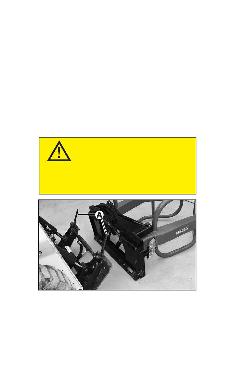
3. Move the loader attaching plate levers (A) to the unlocked (up) posi-
tion either manually or by using the loader controls.
WARNING
AVOID INJURY!
Loader aaching plate levers which are operated
manually may have spring tensioning. Firmly grasp
the levers and move the levers slowly.
13
Installing and Removing
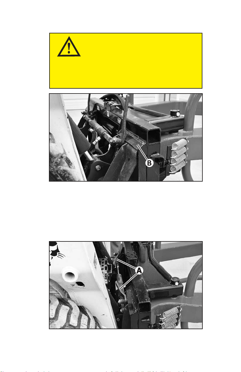
4. Tilt the loader attaching plate forward, and drive the loader forward
until the top edge of the loader attaching plate is under the top ange
(B) of the attachment mounting frame.
5. Raise the loader lift arms slightly until the attaching plate is fully
seated under the top ange.
6. Tilt the attaching plate backward to raise the front of the attachment.
7. Move the loader attaching plate levers (A) to the locked (fully down)
IMPORTANT
AVOID DAMAGE!
Aaching plate levers may be damaged if they
strike the aachment. Be sure the aaching plate
levers do not hit the aachment during installaon.
14
Installing and Removing
position either manually or by using the loader controls.
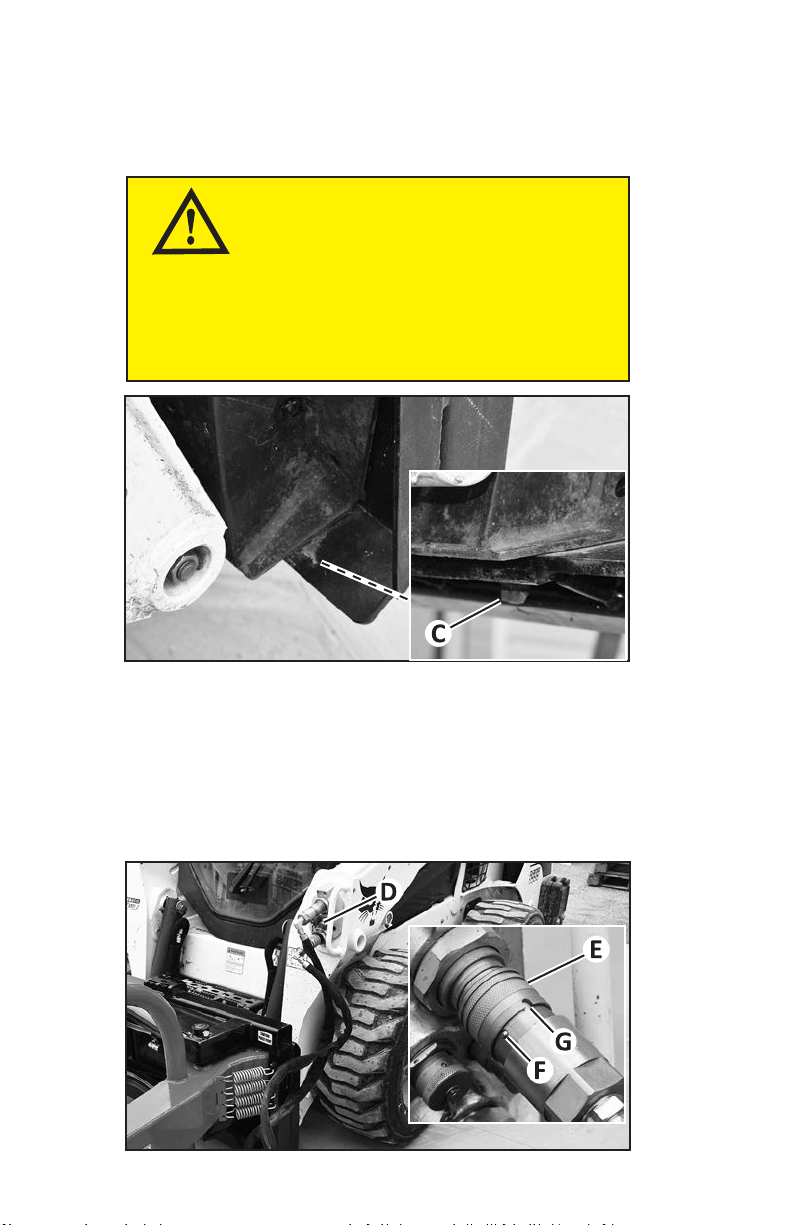
8. Park the loader. (See Parking Safely in this manual.)
Picture Note: Wedge on right side shown. Check the wedges or pins on
both sides of the attachment.
9. Check to be sure the loader attaching plate pins or wedges (C)
extended into the holes in the bottom of the attachment mounting
frame. If not, move the loader attaching plate levers to the unlocked
(up) position and repeat installation.
IMPORTANT
AVOID DAMAGE!
The aachment may come o the loader if it is
not secured to the aaching plate. The aaching
plate pins or wedges must be extended into the
aachment with the levers fully down.
15
Installing and Removing
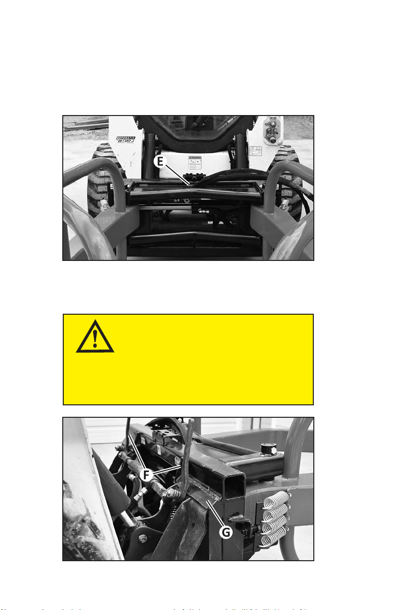
10. Connect the attachment hydraulic hoses to the loader’s front auxilia-
ry couplers (D).
a. Install the male couplers into the female couplers and pull or push
the sleeves (E) to be sure they are locked into place.
b. Rotate the coupler sleeves as shown so the ball (F) is outside the
groove (G) to prevent the coupler disconnecting (Some sleeves
may not have this locking mechanism).
Removing the Aachment
1. Follow the instructions in the loader operator’s manual to remove the
attachment and exit the operator station safely.
2. Fully lower the loader lift arms and the attachment to level ground.
3. Follow instructions in the loader operator’s manual to relieve hydrau-
lic pressure in the front auxiliary hydraulic coupler lines.
4. Stop the loader engine.
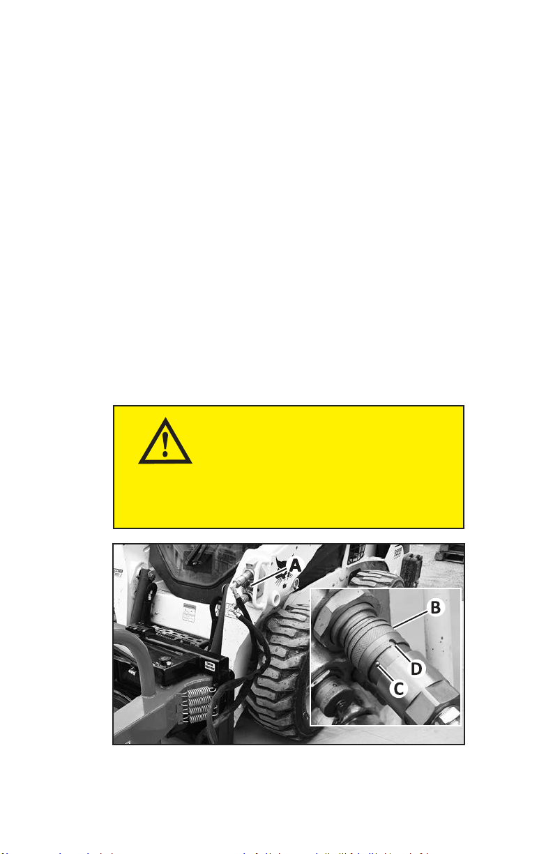
5. Disconnect the attachment hydraulic hoses from the loader’s front
auxiliary couplers (A).
WARNING
AVOID INJURY!
Hydraulic couplers may become hot during op-
eraon. Avoid burns by wearing gloves when
disconnecng hydraulic couplers.
16
a. Rotate the coupler sleeves (B) so the ball (C) is aligned with the
groove (D) to allow the coupler to disconnect (Some sleeves may
not have this locking mechanism).
b. Grasp and push or pull the sleeves to disconnect the couplers.
6. Install protective caps on the couplers if they are provided, and store
the couplers on the attachment hydraulic hoses into the hole on top of
the attachment (E) as shown.
WARNING
AVOID INJURY!
Loader aaching plate levers which are operated
manually may have spring tensioning. Firmly grasp
the levers and move the levers slowly.
Installing and Removing

17
Installing and Removing
7. Move the loader attaching plate levers (F) to the unlocked (up) posi-
tion as shown either manually or by using the loader controls.
8. Tilt the loader attaching plate forward slightly and drive the load-
er backward until the top edge of the attaching plate clears the top
ange (G) of the attachment mounting frame.
18
Operang
Pre-Operaon Inspecon
Before starting operation, inspect the area you will be clearing and in-
spect the attachment.
Inspect the Work Area
1. Conrm the area is clear of bystanders including animals. Establish
a safety zone by keeping bystanders and animals beyond a 100 foot
radius around the attachment when operating.
2. Be aware of any wet or sloping areas and mark the areas to avoid
contact if needed.
Inspect the Aachment
Inspect the attachment to be sure it is in working order. If the attachment
is damaged or not in working order, do not operate until it has been re-
paired by a qualied technician.
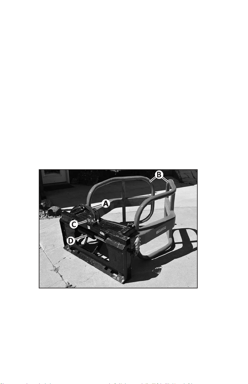
Descripon
A - Hydraulic Hoses
B - Arms
C - Step Area
D - Hydraulic Cylinder
Theory of Operaon
The Bale Squeezer hydraulic hoses are connected to the loader front
auxiliary hydraulic couplers. The loader’s hydraulic controls are used to
extend and retract the Bale Squeezer hydraulic cylinder, which closes
and opens the arms.
19
Operang
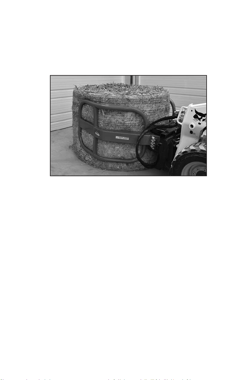
Operaon
1. Follow the instructions in the Installing and Removing section to
install the attachment.
2. Use the loader hydraulic controls to fully open the attachment arms.
3. Raise the loader lift arms to position the attachment arms around the
middle of the bale.
4. Use the loader hydraulic controls to close the arms around the bale,
squeezing until the arms have a rm grip.
5. Raise the loader lift arms to lift the bale o the ground.
6. Keep the attachment lowered as close to the ground during transport
as possible.
7. Be aware of your travel speed when transporting loads.
Transporng the Aachment
On the Loader
When you are not carrying a bale, keep the attachment arms fully open or
fully closed while traveling.
Check to be sure the attachment is correctly installed on the loader before
hauling the loader on a trailor or truck. Follow all loader, truck or trailer
operator’s manual instructions to safely haul the loader.
Hauling the Aachment
Follow all truck or trailer operator’s manual instructions to securely fas-
ten the attachment to the truck or trailer with straps or chains.

20
Servicing
Service Intervals
Every 8 hours or daily:
• Grease the cylinder mount pins.
• Grease the arm mount pins.
• Inspect the attachment and hoses for damage and wear. Replace parts
as needed.
• Check and tighten all hardware.
Lubricaon
Recommended Grease
Standard Lithium
Lubricang the Cylinder Mount Pins
1. Fully open the attachment arms.
2. Park the loader. (See Parking Safely in this manual.)
3. Disconnect the attachment hydraulic hoses from the loader.
4. Lubricate the two grease ttings (A) until grease appears in the
joints.
WARNING
AVOID INJURY!
Disconnect the aachment hydraulic hoses from
the loader before servicing.
This manual suits for next models
1
Table of contents
Other MRF Tractor Accessories manuals


