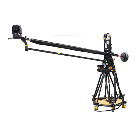
MRMC CINEBOT MINI User manual

CRANES AND RIGS | BROADCAST | HEADS & DSLR | PRODUCT PHOTOGRAPHY | RENTALS
Cinebot Mini
Quick Start Guide
QSG Product Code: MRMC-2272-00
Products covered: MRMC-2227-00, MRMC-2238-00

ii
Cinebot Mini Quick Start Guide
Products covered: MRMC-2227-00, MRMC-2238-00
QSG Product Code: MRMC-2272-00
© 2023 Mark Roberts Motion Control Ltd. All rights reserved.
No part of this publication may be reproduced, transmitted, or translated
by any means — graphical, electronic, or mechanical — including
photocopying, recording, taping, or storage in an information retrieval
system, without the express written permission of Mark Roberts Motion
Control.
Although every care has been taken to ensure that the information in this
document is accurate and up to date, Mark Roberts Motion Control
continuously strives to improve their products and may make changes to
the hardware, firmware, and software described in this document. Mark
Roberts Motion Control therefore cannot be held responsible for any
error or omission in this document.
All product names mentioned herein are the trademarks or registered
trademarks of their respective owners.
Contact information
Mark Roberts Motion Control Ltd.
Unit 3, South East Studios
Blindley Heath
Surrey
RH7 6JP
United Kingdom
Telephone: +44 (0) 1342 838000
Web: www.mrmoco.com
www.mrmocorentals.com

Cinebot Mini Quick Start Guide
iii
Cinebot Mini Model Mover Quick Start GuideCinebot MiniQuick Start Guide
Contents
Chapter 1 Quick Start..................................................................... 1
Important safety instructions ...............................................1
Power and connections................................................1
General care...................................................................1
Location .........................................................................2
Intellectual property .....................................................2
Overview ................................................................................. 3
Attaching the Pinchwheel Assembly to Cinebot Mini
on Track...................................................................................4
Removing/Adding the Wheel Units on the
Cinebot Mini on Track.................................................4
Mounting Cinebot Mini Arm on the Base .........................8
Removing Cinebot Mini Arm from the Base.....................9
Mounting Cinebot Mini Arm on the Columns ...............10
Mounting 300mm Column .......................................10
Mounting 500mm Column .......................................11
Laying the Track for Cinebot Mini on Track....................14
Laying subsequent track sections .............................14
Mounting bearing rail joints .....................................15
Datum Magnet ............................................................16
Connecting the cables (Cinebot Mini on Pedestal) -
Operator’s Position ..............................................................18
Connecting the cables (Cinebot Mini on Pedestal) –
Robot Base - Robot Arm.....................................................19
Connecting the cables (Cinebot Mini on Track) -
Operator’s Position ..............................................................20
Connecting the cables (Cinebot Mini on Track) –
Robot Base - Robot Arm.....................................................21
Starting up the Cinebot Mini on Pedestal system ...........23
Cinebot Mini on Pedestal start-up summary .........24
Shutting down the Cinebot Mini on Pedestal system .....25
Starting up the Cinebot Mini on Track system................26
Cinebot Mini on Track start-up summary..............27
Setting up a Lens in Flair Classic with Tilta motors........28
Setting the Payload for Cinebot Mini................................31
Flair Constraints Feature..................................40
Cinebot Mini remote interface functions.......41
Using Focus Assist with Cinebot Mini..............................42
Cinebot Mini Quick Start Guide
iv
Appendix 1 Troubleshooting and Maintenance ............................. 45
Loading the Flair Program on Cinebot Mini on
Track ......................................................................................45
Appendix 2 Specifications............................................................... 47
Physical and Mechanical.....................................................47
Cinebot Mini on Pedestal ..........................................47
Cinebot Mini on Track...............................................48

Cinebot Mini Quick Start Guide
1
Cinebot Mini Model Mover Quick Start GuideCinebot MiniQuick Start Guide
Chapter 1 Quick Start
Important safety instructions
To ensure the best from the product, please read this manual carefully.
Keep it in a safe place for future reference.
To reduce the risk of electric shock, do not remove the cover from the
unit. No user serviceable parts inside. Refer servicing to qualified
personnel.
Power and connections
This unit must be connected to a mains socket outlet with a
protective earth connection.
This unit is not disconnected from the AC power source as
long as it is connected to the wall outlet.
When not using the unit for a long period of time, ensure that
the AC power cord is disconnected from the wall outlet.
The AC wall outlet should be installed near to the unit and be
easily accessible.
Do not plug in or attempt to operate an obviously damaged
unit.
General care
Do not force switches or external connections.
When moving the unit, disconnect the mains cable and then
disconnect the long umbilical cable.
Do not attempt to clean the unit with chemical solvents or
aerosol cleaners, as this may damage the unit. Use a clean dry
cloth.
Do not use around flammable gas. All electrical equipment can
generate sparks that can ignite flammable gas.
Keep away from pets and children. The head has powerful
motors that can pinch, so take care not to get your hands
trapped in the head or cabling.

Cinebot Mini Quick Start Guide
2
Keep cables tidy. Use cable ties to keep them out of harm’s way.
If you have a head with slip rings then make use of them; avoid
running any cables between the base and the rotating head or
camera.
Location
Installation of this unit should be away from sources of excessive heat,
vibration, and dust.
Keep the brakes on caster wheels on when using the Cinebot Mini on
Pedestal.
Intellectual property
This product includes confidential and/or trade secret property.
Therefore, you may not copy, modify, adapt, translate, distribute, reverse
engineer, or decompile contents thereof.

Cinebot Mini Quick Start Guide
3
Overview
Thank you for using the Cinebot Mini from Mark Roberts Motion
Control (MRMC). Cinebot Mini is designed for reliable day-in, day-out
use in professional studio and Outside Broadcast environments. It is a low
cost, lightweight Moco rig using the Universal Robots UR10e
collaborative robot on a pedestal or track. It provides motion control at
limited speeds and travel range compared to the existing Bolt range, but
adequate for limited complexity and lower speed shoots. Cinebot comes
with optional 500mm and 300mm risers that can be used to raise the height
of the arm
Cinebot Mini on Pedestal has
a lightweight but sturdy
movable pedestal which can be
held down with weights.
Cinebot Mini on Track has a
base designed to move along
precision track. It has removable
trolley wheels for moving
between sets, and can also be
held down with weights at
temporary locations.

Cinebot Mini Quick Start Guide
4
Attaching the Pinchwheel Assembly to Cinebot
Mini on Track
1. After removing the packaging and putting the Cinebot Mini on
Track from the crate, remove the cable tie on the Cinebot Mini base
underside that has been added to secure the pinch wheel assembly
during transport.
2. Push the track motor gear to the teeth of the racking so they are in
mesh.
3. Slightly push the pinchwheel to the rear of the racking and use the
star screw to finger tighten it.
4. Check that the base is now firm on the track and is not able to be
pushed by hand.
Removing/Adding the Wheel Units on the Cinebot Mini
on Track
Cinebot Mini on Track is transported over one length of track on 4 x
wheel units. The 2 x smaller wheels are steering wheels to manoeuvre the
rig and put it in the desired position. The 2 x larger wheels are fixed
wheels. These units can be lowered or removed while the rig is in
operation.
2
3
Racking teeth
Pinchwheel

Cinebot Mini Quick Start Guide
5
To lower the wheels, while pulling the lever on the wheel away from the
rail and lower the handle down.
Similarly lower the other 3 x wheels.
To remove the wheels:
Remove the clip from the castor wheel bracket and detach the wheel
assembly away from the rail.
Lever
Handle

Cinebot Mini Quick Start Guide
6
To add the wheels to the rails:
1. Each wheel assembly can be attached to the rail only to the specific
location on the track. Ensure you find the correct wheel assembly
matching the side of the rail using the label on each. Adjust the
bracket on the wheel so that the handle is lowered and parallel to the
rail and flange on the wheel bracket can go under the rail.
2. Insert the rod in the wheel assembly into the cavity in the rails and
clip it to the rail.
Flange
Rod in wheel
assembly

Cinebot Mini Quick Start Guide
7

Cinebot Mini Quick Start Guide
8
Mounting Cinebot Mini Arm on the Base
1. Ensure that the brakes on the castor wheels in the base are engaged
for the pedestal version and pinchwheel is in mesh with the racking
for the track version.
2. If not done already, remove the moy nut from the interface plate
from the bottom of the arm. Lift the arm directly above the base.
3. While aligning the key on the interface plate on the arm and slot on
the base, lower the arm on the base cavity so that the 4 x M8 insert
into the slots on the interface plate. Lock the arm on the base by
slightly turning the arm clockwise. Tighten the 4 xM8 screws.
4. Reach to the interface plate from within the cavities in the base,
hand tighten the moy nut to the interface plate to secure the arm to
the base. You can optionally source a Mitchell spanner or wrench
locally to do the same.
Arm interface plate
Moy nut
2
3
4

Cinebot Mini Quick Start Guide
9
Removing Cinebot Mini Arm from the Base
1. Ensure that the brakes on the castor wheels in the base are engaged.
2. Reach to the interface plate from within the cavities in the base,
unscrew the moy nut from the interface plate. You can optionally
source a Mitchell spanner or wrench locally to do the same.
3. Loosen the 4 x M8 captive screws that secure the arm to the base
and turn the arm clockwise to release from the base.

Cinebot Mini Quick Start Guide
10
Mounting Cinebot Mini Arm on the Columns
Mounting 300mm Column
1. If the robot arm is mounted on the base, use the procedure in
Removing Cinebot Mini Arm from the Base on page 9 to remove the
arm.
2. Add the 300mm column to the base by aligning the key on the
mounting plate on the column and slot on the base, lower the
column on the base cavity so that the 4 x M8 screws insert into the
slots on the mounting plate on the column. Turn the column
clockwise so that it locks into the base. Tighten the 4 xM8 screws.
3. While aligning the key on the interface plate on the arm to the slot
on the base, lower the arm on the base cavity so that the 4 x M8
screws in the column insert into the slots on the interface plate in
the arm. Lock the arm on the base by slightly turning the arm
clockwise. Tighten the 4 xM8 screws.
4. Reach to the interface plate from within the cavities in the base,
hand tighten the moy nut to the interface plate to secure the arm to

Cinebot Mini Quick Start Guide
11
the base. You can optionally source a Mitchell spanner or wrench
locally to do the same.
Mounting 500mm Column
1. If the robot arm is mounted on the base, use the procedure in
Removing Cinebot Mini Arm from the Base on page 9 to remove the
arm.
2. Add the 500mm column to the base by aligning the key on the
mounting plate on the column and slot on the base, lower the
column on the base cavity so that the 4 x M8 screws insert into the
slots on the mounting plate on the column. Turn the column
clockwise so that it locks into the base. Tighten the 4 xM8 screws.

Cinebot Mini Quick Start Guide
12
3. Secure the column legs to the base by tightening the 3 x wing nuts to
the 3 x pivot brackets, respectively.
4. While aligning the key on the interface plate on the arm to the slot
on the base, lower the arm on the base cavity so that the 4 x M8
screws in the column insert into the slots on the interface plate in
the arm. Lock the arm on the base by slightly turning the arm
clockwise. Tighten the 4 xM8 screws.
5. Reach to the interface plate from within the cavities in the base,
hand tighten the moy nut to the interface plate to secure the arm to
Column Leg

Cinebot Mini Quick Start Guide
13
the base. You can optionally source a Mitchell spanner or wrench
locally to do the same.

Cinebot Mini Quick Start Guide
14
Laying the Track for Cinebot Mini on Track
1. Lay the robot with the first track section on its feet.
2. Raise the two middle feet of the track
section (1 on each rail) so they do not
touch the ground, leaving the rail to rest on
the four corner feet.
3. Level the track in both length and width
directions using a spirit level, by adjusting
the four corner feet of the track. Make sure all four corner feet are
touching the ground (no wobble).
4. Lower the two middle feet until they touch the ground (finger tight
against the ground).
Laying subsequent track sections
1. Lay the next track section in line with the previously laid track
section and as close to it as possible, making sure it is the right way
around.
2. Raise the middle feet of the new track section so they do not touch
the ground.
3. Adjust the height of the new track section to match that of the
previous section by adjusting the two corner feet nearest to the joint
(one on each rail).
4. Level the new track section with a spirit level by adjusting the two
corner feet furthest from the joint (one on each rail).
5. Slide the new track section along the floor against the previous track
to firmly engage the ends of the rails. (Slide the new section — not
the previous section.) You might need to repeat steps 3 to 5 until you
get good alignment of the rails at the joint.
Hint
The four corner feet also determine the track height. If you are laying
track on a level floor, try to use the middle of the height adjustment
range so that subsequent sections have some leeway (in their feet) to
cater for any unevenness in the floor.
Foot

Cinebot Mini Quick Start Guide
15
6. Make sure the rack joint has the correct
spacing by clamping a rack matching block
to it, teeth meshed, using a vice.
7. Firmly tighten the two large bolts that hold
the track sections together at the joint (one on
each rail). You can also use these to help pull
the track sections together, once they are at the
same height.
8. On the new section, lower the six middle feet
until they touch the ground (finger tight against
the ground).
Mounting bearing rail joints
1. At one of the track joints, slide a track bearing (included in the
spares) over the end of the bearing rails.
2. Add one of the long bearing rail joints onto the track.
3. Align the bearing rail joint with the existing rail by sliding the track
bearing over the joint at each end.
4. Insert the screws and tighten them.
5. Slide the track bearings along the rail to the next joint and repeat
steps 1 to 4 for all remaining joints. For the track ends you use the
short bearing rail pieces (with only two holes) and one track bearing
to help with alignment.
Bearing
rail joint

Cinebot Mini Quick Start Guide
16
6. Remove the vice and rack matching block.
Datum Magnet
The track has a Datum magnet which can be
detected by the Datum sensor under the
pinchwheel in the track base. The Datum
magnet defines a fixed reference point on the
track for the electronics. The rig controller
can then use this position as the home
position or zero point, from which all
positions, movements, and soft limits along
the track are measured.
The Limit Switch consists of a magnetic
sensor located on the track motor pinch
wheel on the underside of the rig, and two
magnets which you mount at each end of the
rack. The position of the magnets along the
rack defines the ultimate limits, along the
track, for the rig electronics. You define the
soft limits within the range of the Limit
Switch magnets, so that if the soft limits fail
for some reason and the rig reaches one of
the Limit Switch magnets, the system electronics automatically shut down
any further movement and apply the brakes.
Hint
If you move the Datum magnet to a different position along the
track, remember to change the soft limits in your controller or Flair
computer to cater for the new Home position.
Note
Ensure that the robot is not directly above the datum magnet when
stopping it to put the pinchwheel out of mesh, for example for
transport. Move the robot over along the track before putting the
pinchwheel out of mesh.
Datum
Magnet
Limit
switch
Table of contents
Other MRMC Robotics manuals

MRMC
MRMC CINEBOT Bolt Jr+ User manual

MRMC
MRMC STUDIOBOT TX90 User manual

MRMC
MRMC Bolt Junior User manual

MRMC
MRMC STUDIOBOT XL User manual

MRMC
MRMC BROADCAST TALOS User manual

MRMC
MRMC MOVER RV13 User manual

MRMC
MRMC MRMC-2165-00 User manual

MRMC
MRMC PTA-1 User manual

MRMC
MRMC Bolt Jr+ User manual

MRMC
MRMC Bolt X User manual