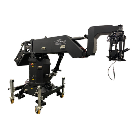
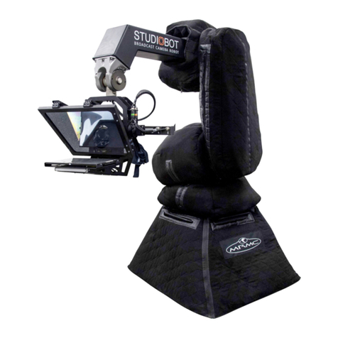
MRMC STUDIOBOT XL User manual

Studiobot XL
Quick Start Guide
QSG Product Code: MRMC-2139-01
Product Covered: MRMC-2011-01

ii
Studiobot XL Quick Start Guide
QSG Product Code: MRMC-2139-01
Product Covered: MRMC-2011-01
© 2021 Mark Roberts Motion Control Ltd. All rights reserved.
No part of this publication may be reproduced, transmitted, or translated
by any means — graphical, electronic, or mechanical — including
photocopying, recording, taping, or storage in an information retrieval
system, without the express written permission of Mark Roberts Motion
Control.
Although every care has been taken to ensure that the information in this
document is accurate and up to date, Mark Roberts Motion Control
continuously strives to improve their products and may make changes to
the hardware, firmware, and software described in this document. Mark
Roberts Motion Control therefore cannot be held responsible for any
error or omission in this document.
All product names mentioned herein are the trademarks or registered
trademarks of their respective owners.
Contact information
Mark Roberts Motion Control Ltd.
Unit 3, South East Studios
Blindley Heath
Surrey
RH7 6JP
United Kingdom
Telephone: +44 (0) 1342 838000
Web: www.mrmoco.com
www.mrmocorentals.com

Studiobot XL Quick Start Guide
iii
Studiobot XL Quick Start GuideStudiobot XLQuick Start Guide
Contents
Chapter 1 Quick Start..................................................................... 1
Overview ................................................................................. 1
Safety procedures for using industrial robots.....................2
Assessing a site ..............................................................3
Installation safety..........................................................3
Software setup ...............................................................5
Operational safety.........................................................5
Mounting the Staubli arm.....................................................7
Mounting the Camera Platform and
Teleprompter .................................................................8
Connecting the cables .........................................................12
Teleprompter connections.........................................14
Starting up the Studiobot XL system.................................14
Configuring the Proximity Scanner ..................................18
Shutting down the Studiobot system.................................25
Moving the Studiobot arm by hand...................................26
Appendix 1 Troubleshooting........................................................... 30
Typical symptoms, causes, and actions .............................30
Moving the axes when the Stäubli arm hard and
soft limits are hit...................................................................31
Appendix 2 Studiobot XL panels .................................................... 34
Studiobot base panel connector summary .......................34
Appendix 3 Specifications .............................................................. 36
Cable Colours ....................................................36

Studiobot XL Quick Start Guide
iv

Studiobot XL Quick Start Guide
1
Studiobot XL Quick Start GuideStudiobot XLQuick Start Guide
Chapter 1 Quick Start
Overview
Thank you for using Studiobot XL Broadcast Camera Robot from Mark
Roberts Motion Control (MRMC). Studiobot XL is designed for reliable
day-in, day-out use in professional studio broadcast environments.
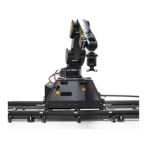
Studiobot XL is equipped with a robotic arm mounted on a movable
pedestal with the robot controller mounted within the pedestal. For ease
of use it can be wheeled to a location of choice and then held down by
four feet. The Teleprompter and the noise reduction cover for minimizing
noise emission makes it a perfect choice for studio environment.

Studiobot XL Quick Start Guide
2
Safety procedures for using industrial robots
Note that the words Robot and Rig are completely interchangeable and
identical in meaning, for the purposes of this document.
Motion Control rigs are potentially dangerous. It is important that you
and everyone else on the set understand the safety notes on the following
pages in order to stay safe.
You should use this document in addition to the normal Safety Manual
instructions that are applicable to all motion control rigs, such as Milos.
This section emphasises the safety concerns that are especially important
around high-speed, high-acceleration, industrial-grade robots which can
cause severe injuries, such as Studiobot XL.
Unlike traditional motion control equipment, Studiobot XL
can get to maximum speed in the blink of an eye - too fast for
someone to be able to quickly move out of the way.
It is ultimately the operator of the rig who is responsible for
the safe use of the equipment so never bypass any of the safety
points listed here.
No one other than a highly trained operator should use the
robot, no matter how simple it looks or is.
This document is for the use of robots for carrying cameras or
props, not people. Additional safety steps should be taken prior
to using a rig to carry people.

Studiobot XL Quick Start Guide
3
Assessing a site
Before setting up Studiobot XL you need to assess the site, paying
particular attention to the following points:
Is the ground or floor firm enough and level enough? You
might have to use boards or bricks to create a level surface. The
surface needs to be strong enough to take the weight of
Studiobot XL without flexing.
Does the site have access? You need to make sure you can
either push Studiobot XL into position on its wheels or carry it
there using a pallet truck or forklift.
Does the site have a power source with sufficient capacity for
the robot and the correct mains voltage?
– Studiobot XL gets its power from the Stäubli CS8 unit
which runs between 200 and 480 Volt, three-phase
power supply (four-wire including Ground). The CS8 is
set at the factory for the three-phase voltage of the
country of use.
– The Robocam Atelier computer that controls Studiobot
XL are auto-switching and can run on 120-240 Volts AC.
Does the site have unusual environmental attributes that
require specialised protection from extreme temperatures,
humidity, rain, or dust?
Installation safety
Due to the large mass of the rigs and the accelerations they
achieve it is important that they are securely mounted, with the
recommended plates and bolts to a secure and concrete floor.
Ensure the floor can support the load and the stresses (see
above).
Ensure the power supply is properly earthed (grounded) and of
the correct voltage (see above).
If the rig is mounted to something other than the floor then
the mount should be heavy and strong enough to take the
forces and not move or fall over during sudden starts and
stops. Use the recommended minimum thickness steel plates.

Studiobot XL Quick Start Guide
4
Check with MRMC if you are unsure of the exact requirements
for your robot.
Check that all cables are securely fixed and are not going to
catch during motion.
Ensure the camera, lens, focus motor, accessories, power
supplies/batteries, etc. are all very securely mounted and will
not come off during sudden motions, to become lethal
missiles.
Ensure all safety accessories are securely attached and in
working order, including emergency stops, safety sensors, etc.
Clearly mark the area around the robot in which no persons
are allowed to enter. As a bare minimum, use brightly marked
tape on the floor, outside the reach of the robot, to indicate the
“No Go Zone”. Ideally, use physical safety barriers, and light
guards/curtains.
Keep stands, lights and accessories out of the No Go Zone, if
possible. If not possible then try to take as much care with their
positioning and the motion of the rig, as if they were a person.
Remember a light, accidentally hit at high speed by the robot,
can be just as dangerous to someone standing outside the No
Go Zone as the robot is to someone standing in the zone.
Where physical safety barriers are impractical, light guards
should be used or similar alternatives such as laser scanners, to
stop anyone entering the No Go Zone during motion.
Ideally have the robot surrounded on all four sides by a safety
barrier, but where that is not practical, ensure that the
maximum number of sides feasible are closed off, and that any
person having to stand within reach of the robot is located as
far away as possible for the shot.
Studiobot XL Quick Start Guide
5
Software setup
Always ensure you have the right configuration for the robot
you are using, such as maximum axis speeds and accelerations.
Prior to running moves, enter in and keep to a minimum all
software axis and Cartesian limits. For example if the main axis
only needs to travel +/-40 degrees then reduce the limit to +/
-40 degrees even though it could do +/-180 degrees. This keeps
the likelihood of operator or software errors to a minimum.
Also check the Cartesian speed and acceleration limits are set
to reasonable values.
Operational safety
Do not use around flammable gas. All electrical equipment can
generate sparks that can ignite flammable gas.
Keep the equipment dry. The system has not been made
weatherproof. Do not use with wet hands.
Always run moves only when standing within easy reach of the
emergency stop.
Always tell the production company
and the crew to keep away from the
robot and not approach it when any of
its red lights are on which indicates it is
powered up. Have them sign the
appropriate safety documents and
disclaimers to ensure they understand
this and are indemnifying MRMC if
anything happens.
Always loudly and clearly indicate to others when the rig is
about to move. Shout “Rig Moving!” if no other means exists.
Always ensure the rig is disabled when someone has to enter
the No Go Zone.
Always run any move or adjusted move slowly at first to check
the motion. Even if you have checked the move previously, if
you make a minor change to it then you need to recheck it.

Studiobot XL Quick Start Guide
6
Keep the software in “slow mode” unless the move has been
tested and is now specifically doing a high speed pass.
In the event that a person or Actor has to be within the no-go
zone during a move (hand model etc.) ensure that they fully
briefed on the safety requirements and that they know not to
change their position or do anything other than the rehearsed
moves without fully warning the operator. Any such person is
to have a clear escape route to allow them to move safely away
from the robot.
During use, repeatedly check the rig mounting points, cables,
camera mount, accessories etc. to ensure nothing has, or is,
working its way loose.
Never bypass any safety hardware or software.

Studiobot XL Quick Start Guide
7
Mounting the Staubli arm
1. Tie the supplied straps around the Staubli arm and insert the hook
from the gantry hoist on to it.
2. Wheel the Studiobot base under the gantry hoist.
3. Use the gantry hoist to gently lift the arm and lower it in position on
the base aligning the screw slots.
4. Tighten the four screws to secure the arm on the Studiobot XL base.
5. Remove the gantry hook and the straps from the arm.

Studiobot XL Quick Start Guide
8
6. Wheel the Studiobot to the location and lower the 4 x feet to secure
to the ground.
7. Once in place, ensure that you fully secure the feet by tightening the
locknut in the feet.
Mounting the Camera Platform and Teleprompter
Locknut
1
2
Teleprompter
Camera platform

Studiobot XL Quick Start Guide
9
1. Raise the camera platform to the robot arm and tighten 4 x M5
screws in the Studiobot XL arm to mount the camera platform on
the arm.
2. Now mount the teleprompter to the camera platform using the
4xM3 screws secure the teleprompter to the camera platform.
3. Add the top bracket to the teleprompter as well as the card cover.
4. Attach the camera to the platform using 2xscrews.
Top bracket
Card cover
Screw the camera to the
camera platform

Studiobot XL Quick Start Guide
10
5. Once firmly secure, attach the pan and tilt connections.

Studiobot XL Quick Start Guide
11
Notes

Studiobot XL Quick Start Guide
12
Connecting the cables
Cable
wrap
J1201
ETH*
E-STOP
VIDEO 1
Tele Power* ROBOT
ETH*
415 Volt
Brake Release Plug
TEACH
PENDANT
The
Ethernet
for the
Camera
can use or
bypass the
Ethernet
hubs in
the system
ONLY
POWER
VIDEO 2 VID 3

Studiobot XL Quick Start Guide
13
ROBOT ONLY
E-STOP
Ethernet
Power Supply:
415 Volt, 3-phase,
5-wire including
Neutral and Ground
VIDEO SIGNALS
Power Supply:
120-240 Volts
hub
5V
Ethernet for Camera
ETHERNET
E-STOP
POWER
24V IN
Broadcast Panel
Rear

Studiobot XL Quick Start Guide
14
Teleprompter connections
12VDC Out
Tally Power In
12VDC In
Teleprompter
Video In
Starting up the Studiobot XL system
Once you have attached all the cables, you power up the rig by switching
on the components in the order described below.
1. Make sure you have secured the area around Studiobot
XL.
2. Release the E-stop on the Studiobot XL base by
turning the red button clockwise until the button pops up.
Also make sure the key is in the clockwise position. Do not
release the other E-stop by the computer stack yet.

Studiobot XL Quick Start Guide
15
3. Power up Studiobot XL itself as follows:
The Studiobot XL power-up sequence takes about three minutes.
When it has completed, the Stäubli CS8 shows an “A” on its display.
4. Power up the Robocam Atelier computer system and all of its
components, including the RT-14 interface box. You can do this
Hint
The Stäubli CS8 is inside the
Studiobot XL base and you
can see the CS8 display and
lights by looking through the
window.
Turn on the power switch on
the side of the Studiobot
Base.
“A”
3
5
Steady
Blinking
cifX board
Window

Studiobot XL Quick Start Guide
16
while the Studiobot XL is powering up (step 3). Do not start the
Robocam Atelier application yet.
5. After Studiobot has finished powering up (step 3) and the Stäubli
CS8 is displaying an “A”, check that the cifX boards in both the
Stäubli CS8 and the Robocam Atelier PC display two steady lights
and one blinking light (see previous diagram). Look through the
window in the Studiobot base to check the lights. This pattern
indicates that the dedicated Ethernet connection running over the
ROBOT ONLY cable is now working.
6. On the Robocam Atelier PC, start the Robocam Atelier application.
Robocam Atelier automatically loads the relevant firmware into all
attached axis boards, including any additional interface boxes that
are attached to the computer stack
7. Release the E-stop that is plugged
into the computer stack, by turning
the button clockwise until the red
button pops up.
Once all E-stop buttons on the
system are up, the Stäubli CS8 display shows “U”.
8. Zero the axes as required in Robocam Atelier. The Studiobot arm
itself does not require zeroing but you need to zero other axes.
9. Engage the robot in Robocam Atelier.
This manual suits for next models
2
Table of contents
Other MRMC Robotics manuals

MRMC
MRMC CINEBOT MINI User manual

MRMC
MRMC Bolt Jr+ User manual

MRMC
MRMC UR10 ROBOT Mover User manual

MRMC
MRMC SHOWBOLT JUNIOR User manual

MRMC
MRMC CINEBOT Bolt Jr+ User manual

MRMC
MRMC MOVER RV13 User manual

MRMC
MRMC BROADCAST TALOS User manual

MRMC
MRMC PTA-1 User manual

MRMC
MRMC MRMC-2165-00 User manual

MRMC
MRMC TX90L User manual