MSA AUER S-Cap-Air User manual

S-Cap-Air
S-Cap-AirS-Cap-Air
S-Cap-Air
EN

2
Deutsch............................3
English.............................8
Italiano...........................13
Español..........................18

3
Inhalt
Seite
1 Hinweis für den Kunden ................................................................................................. 4
2 Technische Beschreibung.............................................................................................. 4
2.1 Allgemeines ....................................................................................................................... 4
2.2 Druckluft-Flasche und Tasche........................................................................................... 4
2.3 Druckminderer / Flaschenventiel....................................................................................... 4
2.4 Haube ................................................................................................................................ 4
3 Anlegen und Benutzung ................................................................................................. 5
4 Nach dem Gebrauch........................................................................................................ 6
4.1 S-Cap-Air wurde mitgeführt, jedoch nicht benutzt ............................................................ 6
4.2 S-Cap-Air wurde mitgeführt und benutzt........................................................................... 6
5 Befüllen der Druckluft-Flasche....................................................................................... 6
6 Verpacken des Gerätes................................................................................................... 6
7 Überprüfungen................................................................................................................. 7
7.1 Regelmäßige Überprüfung ................................................................................................ 7
7.2 Jährliche Überprüfung ....................................................................................................... 7
8 Bestellangaben................................................................................................................ 7
ACHTUNG!
Diese Gebrauchsanleitung weist gem. § 3 des Gesetzes über technische Arbeitsmittel auf bestimmungsge-
mäße Verwendung des Produktes hin und dient zur Verhütung von Gefahren. Sie muß von allen Personen
gelesen und beachtet werden, die dieses Produkt einsetzen bzw. verwenden, pflegen, warten und kontrollie-
ren.
Dieses Produkt kann seine Aufgaben, für die es bestimmt ist, nur dann erfüllen, wenn entsprechend den An-
gaben von MSA AUER eingesetzt bzw. verwendet, gepflegt, gewartet und kontrolliert wird.
Die von MSA AUER für dieses Produkt übernommene Garantie verfällt, wenn es nicht entsprechend den An-
gaben von MSA AUER eingesetzt bzw. verwendet, gepflegt, gewartet und kontrolliert wird.
Vor Auswahl und Einsatz des Produktes muß eine Bewertung vorgenommen werden, ob es für die vorgese-
hene Anwendung geeignet ist. Auswahl und Einsatz unterliegen nicht dem Einfluß von MSA AUER. Unsere
Haftung bezieht sich nur auf die gleichbleibende Qualität des Produktes. Das Vorstehende ändert nicht die
Angaben über Gewährleistung in den Verkaufs- und Lieferbedingungen von MSA AUER.
Das in dieser Gebrauchsanleitung beschriebene Gerät entspricht der Richtlinie 89/686/EWG.
HINWEIS
Das in dieser Gebrauchsanleitung beschriebene Gerät der Baureihe S-Cap-Air entspricht der Richtli-
nie 89/686/EWG. Es ist ein Druckluft-Selbstretter mit Haube nach EN 1146.

4
1 Hinweis für den Kunden
1. S-Cap-Air ist nur für Flucht und Selbstrettung,
jedoch nicht für Arbeitseinsätze einzusetzen.
2. S-Cap-Air ist nicht für Unterwassereinsätze zu
verwenden.
3. S-Cap-Air ist nicht für Rettungseinsätze
und/oder Brandbekämpfung zu verwenden.
4. Falls S-Cap-Air über 5 kg wiegt, (dies ist mit
der 3L 200bar Stahlflasche der Fall) soll das
Gerät gemäß EN 1146 nicht ständig während
einer Arbeitsschicht mitgeführt werden.
5. S-Cap-Air ist geeignet für Erwachsene in guter
physischer und psychischer Verfassung.
6. Regelmäßiges Training und die Kenntnis der
Gebrauchsanleitung werden vorausgesetzt.
7. Mögliche Fluchtwege sind immer so zu planen,
daß sie innerhalb der Haltezeit von S-Cap-Air
sicher bewältigt werden können.
8. S-Cap-Air ist arbeitstäglich zu überprüfen. Bei
fehlender Plombe oder nicht vollständig be-
füllter Druckluft-Flasche, bzw. sonstigen Feh-
lern muß das Gerät zur Überprüfung in den
Service.
9. Nur von MSA ausgebildetes und autorisiertes
Servicepersonal darf Prüfungen und Reparatu-
ren an S-Cap-Air durchführen.
Die Transportverpackung für S-Cap-Air ist in
Übereinstimmung mit den geltenden Vorschriften
auszuwählen.
Nach dem Transport ist S-Cap-Air immer auf seine
Einsatzfähigkeit hin zu überprüfen. (D.h. Sichtprü-
fung auf Beschädigungen, Überprüfung der Plom-
bierung und des Füllzustandes anhand des Mano-
meters.)
2 Technische Beschreibung
2.1 Allgemeines
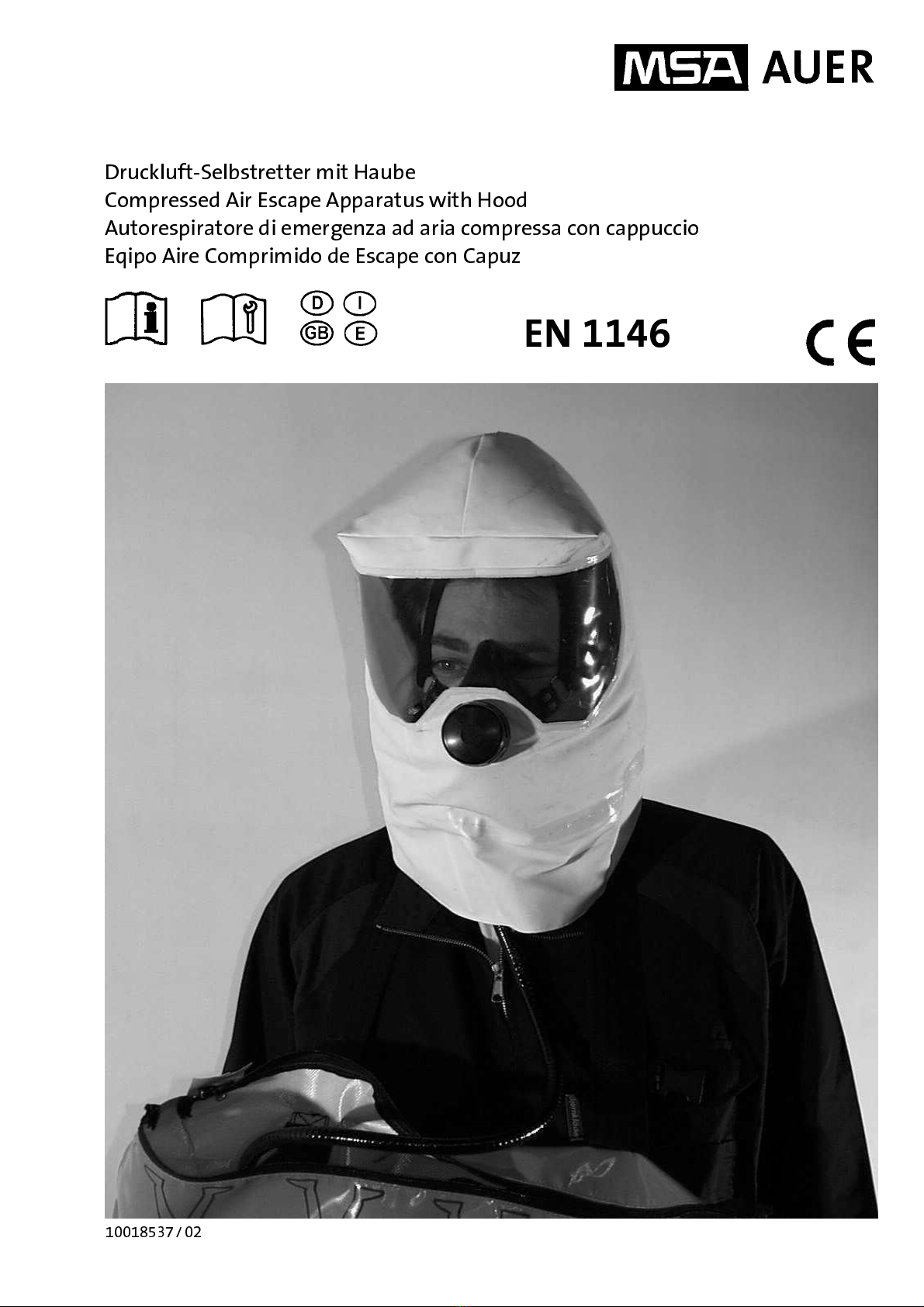
Das MSA AUER Druckluft-Selbstretter mit Haube
S-Cap-Air ist für die Flucht und Selbstrettung aus
schadstoffhaltigen Bereichen. S-Cap-Air ist leicht
und einfach zu bedienen. Das Gerät liefert einen
konstanten Luftstrom zur Atemluftversorgung in die
Haube.
Achtung S-Cap-Air ist ausschließlich für Notfälle
zur Flucht und Selbstrettung zu ver-
wenden.
S-Cap-Air (3Liter, 200 bar) hat eine Einsatzzeit von
15 Minuten. Dies entspricht den Anforderungen der
International Maritime Organization (IMO).
Während der einfachen und eindeutigen Anlege-
prozedur wird die Luftversorgung automatisch ak-
tiviert, Luft strömt in die flexible Haube, welche
leicht aufgesetzt werden kann und sofort Schutz
bietet, auch für Bart- und / oder Brillenträger .
2.2 Druckluft-Flasche und Tasche
Die Druckluft-Flasche entspricht der europäischen
Richtlinie 97/23/ CEE. Die Druckluft-Flasche wird in
der Tasche fixiert getragen. Das Manometer ist
durch ein Fenster in der Tasche ablesbar.
Die Einsatzzeit und Piktogramme zur Verdeutli-
chung der Anlegeprozedur befinden sich auf der
Tasche.
Durch das Reißen an der Schlaufe wird die Luft-
versorgung aktiviert, die Plombe bricht, die Tasche
öffnet sich und die Haube kann entnommen und
angelegt werden.
Beachten! Nur Atemluft gemäß den Anforde-
rungen der EN 12021 oder USCGA
grade D (oder besser) verwenden.
Beachten! Die verwendeten Druckluft-Fla-
schen müssen den nationalen An-
forderungen entsprechen und für
den entsprechenden Druck zuge-
lassen sein.
2.3 Druckminderer / Flaschenventil
Das Ventil ist fest in die Druckluft-Flasche einge-
schraubt. Am Ventil befindet sich die Ventilkappe
mit dem eingesteckten Starterstift. Durch das Rei-
ßen an der Schlaufe wird der Starterstift am Ventil
herausgezogen, das Ventil öffnet und die Luftver-
sorgung ist aktiviert.
Die Luft strömt aus dem Ventil über einen flexiblen
Schlauch durch den Warn-Indikator in die Haube.
Der ständige Luftstrom versorgt den Gerätträger
mit Atemluft und verhindert einen Kohlendioxidan-
stieg in der Haube. Das Manometer am Ventil zeigt
jederzeit den Füllzustand der Druckluft-Flasche an.
2.4 Haube
Die signal-gelbe Haube ist mit einer großen Sicht-
scheibe, einer Halbmaske mit außenliegendem
Ausatemventil und einem Warn-Indikator, der di-
rekt im Blickfeld liegt ausgestattet. Die Atemluft
gelangt über einen Schlauch durch den Warn-
Indikator in die Haube.
Beim Einsatz des Gerätes füllt sich die Haube
ständig mit frischer Atemluft und bildet ein Luftre-
servoir. Hieraus wird die frische Luft über die
Halbmaske eingeatmet und anschließend über das
Ausatemventil aus der Haube in die Umge-
bungsatmosphäre ausgeatmet.
Die Sichtscheibe bietet ein sehr großes Sichtfeld.
Der Warn-Indikator zeigt jederzeit den vorhanden
korrekten Luftstrom (Anzeige: grün) an und warnt
durch Farbwechsel (Anzeige: rot) den Benutzer
zum Ende der Haltezeit die Haube abzunehmen.
Die Innenbänderung der Haube bietet eine auto-
matische, einfache und leichte Positionierung der
Halbmaske über Nase, Mund und Kinn. Die gut sit-
zende Halbmaske und die konstante Luftversor-
gung verhindern einen Kohlendioxid Anstieg in der
Haube.
Die dichtsitzende, flexible Nackendichtung benötigt
kein Einstellen nach dem korrekten Anlegen der
Haube.

5
3 Anlegen und Benutzung
123
S-Cap-Air dem Aufbewah-
rungsort entnehmen und mit
dem Nackenband um den
Hals hängen..
Tasche festhalten, nicht das
Ventil, die Aufreißschlaufe
greifen und nach oben rei-
ßen. Der Luftstrom ist hörbar.
Prüfen, ob der Starterstift
vollständig herausgezogen
wurde. Ist dies nicht der Fall,
Ventil greifen und die Ventil-
kappe vom Ventil vollständig
abschrauben.
SICHERHEITSHINWEIS !
Dieser Schritt startet die
Luftversorgung und die
Haltezeit beginnt.
Hände in die Halsdichtung
der Haube stecken und diese
weiten, Haube über den Kopf
ziehen.
Sitz der Halbmaske prüfen,
ggf. korrigieren.
Halsdichtung soll glatt am
Hals anliegen; es dürfen kei-
ne Haare oder Kleidung ein-
geklemmt sein.
45 6
Indikator im Blickfeld prüfen.
GRÜN: Korrekte Luftversor-
gung in die Haube
ROT: Ende der Haltezeit
Leibgurt schliessen und ein-
stellen. Ruhig und besonnen flüch-
ten. Haube nicht vor dem
Verlassen der Gefahrenzone
absetzen.
Achtung Warnhinweis!
Wenn sich die Füllung der Druckluft-Flasche dem Ende nähert, zeigt dies der Indikator durch den
Farbwechsel nach ROT an, die CO2-Konzentration in der Haube steigt an und die Haube muß ab-
gesetzt werden.
Benutzte Geräte müssen durch ausgebildetes Personal instandgesetzt werden.

6
4 Nach dem Gebrauch
4.1 S-Cap-Air wurde mitgeführt, jedoch
nicht benutzt:
10. Sichtprüfung auf etwaige Beschädigungen.
Beschädigte Teile ersetzen, bzw. Gerät in den
Service geben.
11. Füllzustand der Druckluft-Flasche mit Mano-
meter prüfen ob Anzeige im grünen Bereich.
Verplombung prüfen. Gerät ggf. befüllen bzw.
in den Service geben.
12. Gerät ggf. äußerlich säubern.
13. Gerät an den Aufbewahrungsort zurückbrin-
gen.
4.2 S-Cap-Air wurde mitgeführt und
benutzt:
1. Achtung! Das Gerät nicht in Reinigungs-
lösungen oder Wasser eintauchen
2. Haube und Schlauch vom Ventil trennen.
3. Haubeninnen- und Außenseite mit einem
feuchten Tuch gründlich reinigen und mit
Desinfektionstuch desinfizieren. Anschließend
mit einem fusselfreien weichen Tuch trocken
reiben.
4. Halbmaske mit einem milden Desinfektions-
mittel desinfizieren, klarspülen und trocknen
(direktes Sonnenlicht oder Hitzestrahlung
vermeiden).
5. Druckluft-Flasche befüllen (siehe unten)
6. Bei Bedarf das Haubenvisier innen mit Anti-
beschlagmittel (D2260 700) behandeln.
7. Gerät verpacken (siehe unten).
8. Gerät an den Aufbewahrungsort zurückbrin-
gen.
5 Befüllen der Druckluft-Flasche
Achtung! Nur Atemluft gemäß den Anforderun-
gen der EN 12021 oder USCGA grade
D (oder besser) verwenden. Kompres-
soren und Fülleinrichtungen sind aus-
schließlich von geschultem Personal zu
bedienen. Alle Warn- und Sicherheits-
hinweise sind zu beachten.
1. Plombe bzw. Plombenreste ggf. entfernen und
den Reißverschluß vollständig öffnen.
2. Haube herausnehmen, Ventil freilegen und
Auslösevorrichtung überprüfen. Der Starterstift
ragt aus der Kappe heraus [der Starterstift ist
parallel zum Schlauchanschluß nach oben
ausgerichtet] und das Ventil ist geschlossen
[Kappe ist handfest aufgeschraubt].
3. Schutzkappe vom Füllstutzen am Ventil ent-
fernen.
4. Füllstutzen mit einem 200 bar Füllanschluß
verbinden und auf 207 bar befüllen. (Anleitung
des Kompressors beachten und ggf. notwen-
dige Adapter verwenden.)
5. Nach dem Füllen das Ventil kurz durch Los-
schrauben der Kappe öffnen, anschließend
sofort wieder schließen, bis der Luftstrom
stoppt. Zusätzlich noch weitere 45° ±15° zu-
schrauben. Jetzt muß der Starterstift parallel
zum Schlauchanschluß ausgerichtet sein. Ist
dies nicht der Fall, Kappe nochmals lösen und
Starterstift entfernen und auf der gegenüber-
liegenden Seite in die Kappe einstecken und
Ventil erneut, wie oben erklärt, schließen.
Hinweis : Das zusätzliche Festschrauben der
Kappe mit einer Drehung von 45° ±15° über
den Punkt ‘Ventil geschlossen‘ [kein Luftstrom
am Auslass] hinaus, sorgt für ein korrekt dicht
geschlossenes Ventil. Ein zu festes Auf-
schrauben der Kappe würde bei der Aktivie-
rung die Aufreißkraft erheblich vergrößern.
Normalerweise ist ein Nachfüllen der Druck-
luft-Flasche nicht erforderlich
6. Nach dem Füllen den Füll-Anschluss entlüften
und die drucklose Verbindung lösen (ggf. Ad-
apter entfernen).
7. Füllzustand überprüfen, Manometeranzeige ist
nach dem Abkühlen auf Raumtemperatur im
grünen Bereich.
8. Füllstutzen mit Schutzkappe wieder verschlie-
ßen.
9. Gerät verpacken (siehe unten).
6 Verpacken des Gerätes
1. Nach dem Befüllen des Gerätes und Ver-
schließen des Füllanschlusses wird die ange-
schlossene Haube verpackt, indem der Luft-
führungsschlauch die Druckluft-Flasche ent-
lang zum Ende geführt und dann die Haube in
Gegenrichtung oben auf gelegt wird, wobei
diese (bei korrekter Packlage) nicht an das
Ventil heranreicht.
2. Der Haken am Ende des Aufreißbandes wird
in den Starterstift eingehakt. Das Aufreißband
soll nicht verdreht und frei beweglich sein und
oben auf der Haube liegen.
3. Nun den Reißverschluß vollständig bis an das
Ende über den Zahn-Ausschnitt in der Reiß-
verschlußkette hinaus schließen. Dabei ist die
Haube in Packlage zu halten, darauf zu ach-
ten, daß in den Reißverschlußzähnen nichts
eingeklemmt wird und die Aufreißschlaufe au-
ßerhalb der Tasche ist.
4. Sicherstellen, daß das Manometer im Ta-
schenfenster sichtbar ist. [Haube ist nicht im
Fenster sichtbar].
5. Die Taschen-Lasche durch die Aufreiß-
schlaufe legen und somit fixieren.

7
6. Die Plombe wird durch die Ösen der Tasche
gezogen, damit wird die Lasche fixiert und die
Schlaufe des Aufreißbandes gesichert. Die
Verplombung soll so eng als möglich, jedoch
spannungsfrei und noch beweglich sein.
7. Jetzt ist S-Cap-Air einsatzbereit.
(Wenn die Aufreißschlaufe hochgerissen wird,
bricht die Plombe, der Starterstift wird aus der
Ventilkappe herausgezogen und das Ventil
öffnet, Luft strömt in die Haube, der Reißver-
schluß der Tasche öffnet sich und die Haube
kann entnommen werden.) Verplombungsset
(Best.-Nr. 10023512, Pg. mit 25 St.).
7 Überprüfungen
7.1 Regelmäßige Überprüfungen
Alle einsatzfähigen Geräte sind monatlich zu über-
prüfen, auch wenn sie zentral gelagert werden.
Personen zugeordnete Geräte sind bei Überga-
be und anschließend arbeitstäglich zu überprü-
fen. Geräte, die ortsgebunden zum sofortigen
Notfalleinsatz gelagert werden, sind ebenfalls
arbeitstäglich zu prüfen.
1. Manometer-Kontrolle
Druckluft-Flasche muß vollständig gefüllt sein
2. Allgemeine Zustands-Kontrolle
Gerät und Tasche sind sauber und unbeschä-
digt
3. Plomben-Kontrolle
Plombe ist einwandfrei und unbeschädigt
4. Zugangs-Kontrolle
Zugriff auf das Gerät darf nicht verstellt oder
versperrt sein
Geräte, die eine Kontrolle nicht bestehen und
die zur jährlichen Überprüfung anstehen, müs-
sen zum Service gegeben werden.
7.2 Jährliche Überprüfung
7.2.1 Sichtkontrolle
Überprüfung auf mechanische Beanspruchungen
wie Risse, Materialbrüche, Schnitte, Abschürfun-
gen oder sonstige Materialveränderungen an den
folgenden Teilen:
- Tragetasche, Bänderung und der Startauslö-
sungevorrichtung.
- Luftführungsschlauch und Anschlußstückmit O-
Ring. Verhärtete und oder brüchige Schläuche
sind zu ersetzen. O-Ringe sind als Ersatzteile
erhältlich [Best.-Nr.: 10024118 (Pg. mit 10 St.)].
- Haube, Nackendichtung und Halbmaske. Die
Ventilscheibe im Ausatemventil ist spätestens
alle 3 Jahre zu ersetzen. Ersatzteile sind erhält-
lich [Best.-Nr. : D2055749 (Pg. mit 10 St.)]
- Flaschen-Ventil / Druckminderer und Manome-
ter
- Druckluft-Flasche, Überprüfungen gemäß den
nationalen Bestimmungen sind durchzuführen
(z.B. TÜV-Prüfungen)
7.2.2 Funktionsprüfung
Neben der Sicht- und Materialüberprüfung wird die
korrekte Funktion des Gerätes überprüft. Hierzu
wird das gefüllte Gerät gestartet und der Warnindi-
kator überprüft. Nach dem Start muß die Anzeige
grün sein. Nach mindestens 15 Minuten und
maximal 21 Minuten muß die Anzeige nach rot
wechseln. Während dieser Prüfzeit muß die
Druckanzeige des Manometers von voll nach leer
wechseln, Die Überprüfung ist zu protokollieren,
mit den entsprechenden Befunden und Details
sowie der Serial Nummer - auf dem Gerät ist der
Zeitpunkt der nächsten jährlichen Überprüfung zu
vermerken. Nach erfolgreicher Überprüfung wird
das Gerät gemäß dieser Anleitung gefüllt und ver-
packt.
Achtung! Bei Schäden oder Funktionsstörungen
muß das Gerät in den Service geben
werden.
8 Bestellangaben
Bezeichnung Bestell-Nr.
S-Cap-Air, Flasche ungefüllt 100 17 668
S-Cap-Air, Flasche gefüllt 100 32 181
S-Cap-Air light, Flasche ungefüllt 100 33 919
S-Cap-Air light, Flasche gefüllt 100 34 561
Tasche S-Cap-Air, Ersatz 100 18 520
Haube S-Cap-Air, Ersatz 100 19 481
Clip (Pckg. mit 5 Stück) 100 19 483
Filter, Filzscheiben S-Cap-Air
(Pckg. mit 10 Stück) 100 19 508
Ventilkappe und Starterstift 100 19 484
O-Ring für Anschlußstück
(Pckg. mit 10 Stück) 100 24 118
Plomben Kit (25 Stück) 100 23 512

8
Contents
Page
1 Important Information to User........................................................................................9
2 Technical Description......................................................................................................9
2.1 General ..............................................................................................................................9
2.2 Cylinder and Bag................................................................................................................9
2.3 Regulator / Cylinder Valve..................................................................................................9
2.4 Hood...................................................................................................................................9
3 Donning and Use ............................................................................................................10
4 After Use ..........................................................................................................................11
4.1 When S-Cap-Air has been worn but not operated...........................................................11
4.2 When S-Cap-Air has been worn and operated................................................................11
5Charging..........................................................................................................................11
6 Packing ............................................................................................................................11
7 Checks .............................................................................................................................12
7.1 Regularly Check................................................................................................................12
7.2 Once a Year......................................................................................................................12
8 Ordering Information......................................................................................................12
Notice!
Like any piece of complex equipment, this MSA AUER product will do the job it is designed to do only, if it is
used and serviced in accordance with the manufacturer’s instructions. This manual must be carefully read by
all individuals who have or will have responsibility for using or servicing this product.
The warranties made by MSA AUER with respect to this product are voided if the product is not used and
serviced in accordance with the instructions in this manual.
Before choosing and using this product, it is required to assess whether it is suitable for the application in-
tended.
Selection and use are beyond the control of MSA AUER. Therefore, the liability of MSA AUER covers only the
steady quality of this product.
The above does not alter statements regarding the warranties and conditions of sale and deliveries of
MSA AUER.
The S-Cap-Air apparatus described in these Instructions for Use is in accordance with Directive
89/686/EEC. It is a compressed air escape apparatus with hood according to EN 1146.

9
1 Important Information to User
1. The S-Cap-Air apparatus is designed for
emergency situations only and should not be
used for entry or re-entry into irrespirable at-
mospheres.
2. The MSA escape apparatus S-Cap-Air is not
to be used for underwater escape activities.
3. The S-Cap-Air is not for rescue or fire fighting
purposes.
4. If the S-Cap-Air weighs more than 5 kg, it
must not be worn during a complete work shift
according to EN 1146. (Normally the S-Cap-
Air with steel cylinder weighs more than 5 kg.)
5. Only adults in good physical and physiological
condition should use the S-Cap-Air.
6. The user of S-Cap-Air must have received full
training in its use and have read and under-
stood this manual before using.
7. Always ensure that the length of the escape
route is within the duration stated on the
S-Cap-Air.
8. If the anti-tamper tag is broken the apparatus
must be checked, recharged if required, and a
new tag applied.
9. Only holders of a valid MSA Service Certifi-
cate may carry out full service and test of S-
Cap-Air.
It is essential that the S-Cap-Air are transported in
suitable packaging with due regard to all applicable
legislation.
After transportation ensure that the bag and con-
tents including the gauge have not been damaged
and that the anti-tamper tags are intact.
2 Technical Description
2.1 General
The escape apparatus S-Cap-Air is a compressed
air breathing apparatus to be used for emergency
escape from irrespirable atmospheres. It has been
designed and tested in accordance with EN 1146
to demonstrated compliance with safety require-
ments of EC Directive 89/686/EEC. Type-
examination performed by INSPEC; UK (Notifying
Body: - Inspec Certification [0194] Upper Wingbury,
Courtyard Wingrave, Aylesbury, Bucks, U.K.). The
S-Cap-Air is a lightweight apparatus that is simple
to use and gives a consistent flow of breathable air.
Note! The S-Cap-Air apparatus is to be used
for emergency escape only
The S-Cap-Air has duration of 15 minutes. This is
the duration required by the International Maritime
Organization (IMO).
In the apparatus a fast positive method of opera-
tion permits air to pass from the compressed cylin-
der into a flexible hood which can be slipped over
the head in a fast maneuver without complicated
adjustment and provides protection to any wearer,
including those with beard and/or spectacles.
2.2 Cylinder and Bag
The compressed air cylinder is manufactured in
accordance with the Directive 97/23/EEC. It is car-
ried and fixed in the bag. The pressure gauge is
readable through a window.
The duration time for the apparatus and pictorial
user instructions are noted on the bag.
When pulling the firing strap the anti-tamper tag
breaks the airflow starts and the bag is opened so
that the hood can be taken and be pulled over the
head.
Note! The air supply shall meet the require-
ments for breathable air of EN 12021
or USCGA grade D (or better).
Note! The compressed air cylinder used with
this apparatus shall comply with na-
tional regulations. The cylinder shall
be approved with respect to the ap-
propriate pressure.
2.3 Regulator / Cylinder Valve
The regulator is mounted on the cylinder. The
regulator has a quick start function. By pulling the
firing strap the cylinder valve is opened in one
movement. When the firing pin is drawn the airflow
starts.
From the outlet of the regulator a flexible hose
leads the flow of air into the hood. The airflow
minimizes CO2 build up. A constant reading pres-
sure gauge is fitted to the regulator, providing a
continuous indication of the cylinder pressure.
2.4 Hood
The hood assembly consists of a bright yellow
hood, an inner Mask, a visual alarm indicator in the
field of vision and the air supply hose.
When the S-Cap-Air is operated, the hood is filled
with air and provides a reservoir of air. When the
user takes a breath, air goes from the hood to the
inner mask and will be inhaled. Exhalation goes
through an exhalation valve from the inner mask to
the ambient atmosphere.
The visor is designed for maximum field of vision
during escape. The visual indicator shows duration
status information and indicates when to remove
the hood as the cylinder is empties.
The inner harness provides automatic and easy
adjustment for the inner mask. The harness design
guides the mask onto the user's face and assumes
the correct position. The inner mask and the air
supply prevent the build up of high levels of carbon
dioxide.
The neck seal accommodates a wide range of fits
and needs no adjustments after donning.

10
3 Donning and Use
123
Remove the S-Cap-Air from
its stowage. Put your head
through the neck strap.
Hold the bag, not the cylinder
valve, pull the firing strap up-
wards. Listen for airflow.
Check that the firing pin is
fully withdrawn.
If the firing pin is still in place,
access the valve and un-
screw the cap completely.
SAFETY WARNING!:
Duration of apparatus
starts now.
This action has started the
airflow.
Insert hands into the neck
seal opening and pull the
hood over the head. Adjust
inner mask and neck seal to
seal. Ensure that hair / cloth-
ing is not trapped under the
neck seal.
45 6
Check the indicator in the
visor.
GREEN : OK
RED: End Of Duration
Tighten waist belt. Make your escape from the
area. Do not remove hood
until well clear of danger.
Note!
When the cylinder is almost empty the green warning disc, visible inside the hood, will change to red,
CO2will start to increase and the hood must be removed.
Once the S-Cap-Air has been used it must be returned for servicing and maintenance, including
recharging, by trained personnel.

11
4 After Use
4.1 When S-Cap-Air has been worn but
not operated:
1. Examine the apparatus for any signs of dam-
age. Damaged parts shall be replaced or sent
for service.
2. Check that the cylinder is fully charged and
the anti-tamper tag is intact. If not, send the
apparatus for service / charging.
3. Clean the bag if necessary.
4. Replace the apparatus to its storage point.
4.2 When S-Cap-Air has been worn and
operated:
1. Caution: Do not immerse the device
2. Remove the hood and supply hose from the
regulator
3. Clean the internal and the external surface of
the hood with a damp cloth and a Sanitizing
Wipe. Dry the above with a soft lint free cloth.
4. Clean the inner mask with a mild disinfectant
sanitizing wipe.
5. Recharge the cylinder as described under
Charging.
6. Demisting Solution [Part No. D2260 700] is
available to polish the visor if this is necessary
7. Pack the apparatus as described under
Packing.
8. Replace the apparatus in its storage point.
5 Charging
Note! Air used to charge cylinders must conform
to EN 12021 or USCGA grade D (or bet-
ter). High pressure compressors and
charging apparatus must only be used by
trained operators and all safety procedures
must be observed.
1. Break the tamper proof tag (if necessary) and
open the zipper on the bag to its full length.
2. Uncover the valve arrangement and check
that the firing pin is in place [the head of the
pin should be on the same side as the outlet
port] when the cap is tightly screwed into valve
closed position.
3. Remove the dust cap from the charging port
on the cylinder valve
4. Connect to a suitable [200 bar] supply using
any necessary adapters and charge the cylin-
der to 207 bar.
5. When the cylinder is full close the supply valve
of the charging system to the S-Cap-Air and
vent the connection to atmosphere.
Open the valve by turning the cap counter-
clockwise until the airflow starts, then immedi-
ately close the valve until the airflow just
stops. Now turn the cap clockwise 45° ±15°.
Check the position of the firing pin. The head
of the pin should still be on the same side as
the outlet port. If this is not the case quickly
slacken the cap, remove the pin and replace it
in the correct orientation. Close the valve until
the airflow just stops and then turn the cap
clockwise 45° ±15°.
Attention: Turning the cap through an angle
of approx. 45° is done to ensure that ade-
quate, air tight sealing of the valve is
achieved. Turning the cap through greater an-
gles may result in excessively high pull out
forces for the firing pin.
Check the cylinder pressure and top up if nec-
essary. Topping up will not normally be re-
quired.
6. Remove any charging adapters used. The
cylinder pressure gauge reading (cylinder at
room temperature) must be clearly in the
green section.
7. Replace the dust cap on the charging port.
8. Complete the packing of the S-Cap-Air as de-
scribed below.
6 Packing
1. Once the cylinder is fully charged the dust cap
must be replaced on the charging port. The re-
connected hood is packed by laying the hose
along the top of the cylinder away from its con-
nection point towards the closed end of the
zipper and then laying the hood back towards
the regulator, it should not reach the regulator
if packed correctly.
2. Connect the clip at the end of the strap to the
firing pin and check that the strap is not tan-
gled and is free to move. The strap lays on top
over the packed hood.
3. Ensuring that no material is trapped in the
teeth close the zip until it is passed the break
point in the zip teeth, holding the hood in
place, keeping the loop in the strap out side
the bag
4. Make sure that the pressure gauge is read-
able through the bag window [you should not
see the hood].
5. Fold the flap over and feed the strap loop
through it to trap it.
6. Feed the anti tamper tag through the eyelets
in the bag and flap but under the strap loop
and close the tag. Adjust the size of the tag
loop such that it is as small as possible but still
slightly loose. The tag should not be under
tension.
7. The S-Cap-Air is now in its ready for use state.
(When the firing strap is pulled the tamper
proof tag breaks.The firing pin is pulled from
the cylinder valve, airflow commences and the
zipper opens.)

12
7 Checks
7.1 Regularly Checks
It is mandatory that all escape equipment be
checked at monthly intervals, even in a central
store.
In addition apparatus issued to individuals
should be checked at issue and then daily.
Apparatus in ready to use lockers should also
be checked daily.
1. Check that the contents gauge shows fully
charged.
2. Check that the bag is clean and undamaged.
3. Check that the anti-tamper tag is located and
unbroken.
4. Check that access to the bag is unobstructed.
Apparatus that fails any of these checks must
be withdrawn and sent for maintenance and at
scheduled annual service intervals
7.2 Once a Year
7.2.1 Visual Inspection
Check that there are no mechanical damages such
as cuts, tears, abrasions or mechanical damages
on the following parts:
- The carrying bag, straps / bands and the firing
mechanism
- The air hose connectors and O-rings. Exces-
sively stiff hoses should be replaced with new
ones. Hose connection port O-rings are avail-
able as spares [MSA part no. 10024118; (10
pcs)]
- Hood, neck seal and mask. The valve disc in
the exhalation valve must be replaced every 3
years and spares are available D2055 749
(10 pcs)].
- Cylinder valve / first stage regulator and pres-
sure gauge
- Cylinder, check that the cylinder is tested ac-
cording to local and national regulations
7.2.2 Functional Checks
In addition to the visual inspection described the
device should be tested to ensure that it functions
correctly. Operating the device performs this test
and checking that the flow alarm indicator remains
green until a minimum of 15 minutes [and maxi-
mum of 21 Minutes] has elapsed before turning
red. The pressure gauge must indicate from full to
empty during the test. Once the inspection and
tests are complete the cylinder should be re-
charged and made ready for service as described
in the charging and packing sections. Record in-
spection and test of the S-Cap-Air including details
of the actual date and serial number of the set. Any
damaged parts must be replaced before it can be
returned to service and all malfunctions corrected.
Note! Any signs of damage or malfunction:
Send for service or replace necessary
parts.
8 Ordering Information
Description Part Number
S-Cap-Air, Cylinder empty 100 17 668
S-Cap-Air, Cylinder charged 100 32 181
S-Cap-Air light, Cylinder empty 100 33 919
S-Cap-Air light, Cylinder charged 100 34 561
Bag S-Cap-Air, Spare 100 18 520
Hood assembly, Spare 100 19 481
Clip (pcs 5) 100 19 483
Felt Disc (pcs 10) 100 19 508
Cap and Firing Pin 100 19 484
Connection Port O-Ring (pcs 10) 100 24 118
Anti-tamper tag kit (pcs 25) 100 23 512

13
Indice
Page
1 Informazioni importanti per l’Operatore....................................................................... 14
2 Descrizione Tecnica ....................................................................................................... 14
2.1 Informazioni Generali........................................................................................................14
2.2 Bombola e Borsa..............................................................................................................14
2.3 Regolatore / Valvola bombola........................................................................................... 14
2.4 Cappuccio......................................................................................................................... 14
3 Indossamento e Utilizzo................................................................................................. 15
4 Dopo l’uso....................................................................................................................... 16
4.1 Quando S-Cap-Air è stato indossato, senza essere messo in funzione.......................... 16
4.2 Quando S-Cap-Air è stato indossato e messo in funzione.............................................. 16
5 Ricarica............................................................................................................................ 16
6 Imballo ............................................................................................................................. 16
7 Controlli........................................................................................................................... 17
7.1 Controlli regolari................................................................................................................ 17
7.2 Annualmente..................................................................................................................... 17
8 Numeri di catalogo ......................................................................................................... 17
Avvertenza!
Come ogni componente di attrezzatura complessa, questo prodotto MSA AUER espleterà la funzione
preposta, esclusivamente se il suo uso e la sua manutenzione avverranno in conformità con le istruzioni
fornite dal produttore. Tutti coloro responsabili dell’uso e della manutenzione del prodotto dovranno leggere
attentamente le istruzioni contenute in questo manuale.
Le garanzie concesse da MSA AUER relative a questo prodotto saranno ritenute nulle qualora il suo uso e la
sua manutenzione non avvenissero conformemente alle istruzioni contenute in questo manuale.
Prima di scegliere e utilizzare questo prodotto, è necessario stabilire che sia adatto per il tipo di applicazione
intesa.
La scelta e l’uso del prodotto sono fuori dal controllo di MSA AUER. Quindi, la responsabilità di MSA AUER
riguarda solo la qualità dello stesso.
Quanto sopra non modifica le dichiarazioni in merito alle garanzie ed alle condizioni di vendita e fornitura di
MSA AUER.
L’apparecchio S-Cap-Air descritto in queste Istruzioni per l’Uso è conforme alla Direttiva 89/686/CEE.
Si tratta di un apparecchio di fuga ad aria compressa con cappuccio conforme alla norma EN 1146.

14
1 Informazioni importanti per
l’Operatore
1. L’apparecchio S-Cap-Air è stato realizzato
esclusivamente per situazioni di emergenza e
non deve essere usato per entrare o rientrare in
atmosfere irrespirabili.
2. L’apparecchio di emergenza MSA S-Cap-Air
non deve essere usato per operazioni
subacquee
3. L’S-Cap-Air non è stato realizzato per
operazioni di salvataggio o antincendio
4. Se l’S-Cap-Air ha un peso maggiore a 5 kg, non
deve essere indossato per un turno di lavoro
completo conformemente alla norma EN 1146.
(Solitamente il peso di S-Cap-Air con bombola
in acciaio è maggiore a 5 kg.)
5. S-Cap-Air deve essere utilizzato soltanto da
operatori adulti in buone condizioni fisiche.
6. L’operatore che utilizza S-Cap-Air deve aver
seguito un corso di addestramento completo
sull’uso dell’apparecchio e letto il manuale di
istruzioni prima dell’uso.
7. Assicurasi sempre che la lunghezza del
percorso di fuga corrisponda alla durata
specificata
sull’S-Cap-Air.
8. Se il sigillo anti-manomissione non è intatto,
controllare l’apparecchio, se necessario
provvedere alla ricarica e applicare un nuovo
sigillo.
9. Solo coloro che dispongono di un Certificato di
Assistenza MSA possono effettuare assistenza
e controlli completi dell’apparecchio S-Cap-Air.
E’ importante che l’ S-Cap-Air sia trasportato in
apposita borsa, tenendo in considerazione tutte le
normative vigenti.
Dopo il trasporto assicurarsi che la borsa ed il suo
contenuto, compreso il manometro, non abbiano
subito danni e che i sigilli anti-manomissione siano
ancora intatti.
2 Descrizione Tecnica
2.1 Informazioni Generali
S-Cap-Air è un respiratore ad aria compresa da
utilizzare in casi di emergenza, nei casi in cui è
necessario abbandonare un’atmosfera irrespirabile.
E’ stato realizzato e sottoposto a controlli
conformemente alla norma EN 1146 per dimostrare la
conformità con i requisiti di sicurezza della Direttiva
89/686/CEE. Omologazione eseguita da INSPEC UK
(Organismo Notificato: - Inspec Certification [0194]
Upper Wingbury, Courtyard Wingrave, Aylesbury,
Bucks, U.K.). S-Cap-Air è un apparecchio leggero,
semplice da utilizzare che fornisce un flusso costante
di aria respirabile.
Nota! L’apparecchio S-Cap-Air deve essere
usato solo in situazioni di emergenza
La durata di S-Cap-Air corrisponde a 15 minuti. Si
tratta della durata richiesta dall’ Organizzazione
Marittima Internazionale (IMO).
Grazie al metodo di funzionamento rapido, l’aria
passa dalla bombola di aria compressa in un
cappuccio flessibile che può essere indossato
velocemente senza necessità di effettuare complicate
regolazioni e garantisce la protezione per qualsiasi
operatore, compresi coloro con barba e/o occhiali.
2.2 Bombola e Borsa
La bombola di aria compressa è realizzata
conformemente alla Direttiva 97/23/CEE. E’ traspor-
tata e fissata nella borsa. Il manometro è leggibile
attraverso una “finestrella” trasparente.
Sulla borsa sono indicati la durata dell’apparecchio
ed alcuni pittogrammi relativi all’uso dello stesso.
Quando viene tirata la cinghia di attivazione, il sigillo
anti-manomissione si rompe, si attiva il flusso d’aria e
la borsa si apre ed è quindi possibile sfilare il
cappuccio e indossarlo.
Nota! L’alimentazione dell’aria deve
corrispondere ai requisiti per l’aria
respirabile della norma EN 12021 o
USCGA Grado D (o migliore).
Nota! La bombola di aria compressa usata con
questo apparecchio deve essere
conforme alle normative nazionali. La
bombola deve essere adeguata alla
pressione utilizzata.
2.3 Regolatore / Valvola bombola
Il regolatore è montato sulla bombola. Il regolatore
dispone di una funzione di “avvio rapido” (quick start).
Tirando la cinghia di attivazione, la valvola della
bombola si apre con un unico movimento. Quando si
estrae il perno di attivazione, parte il flusso d’aria.
Dall’uscita del regolatore, un tubo flessibile conduce il
flusso di aria nel cappuccio. Il flusso d’aria minimizza
la formazione di CO2. Un manometro di pressione a
lettura costante è collegato al regolatore, garantendo
un’indicazione continua della pressione della
bombola.
2.4 Cappuccio
Il gruppo del cappuccio consiste di un cappuccio
giallo brillante, di una maschera interna, di un
indicatore di allarme posto nel campo visivo e di un
tubo flessibile di alimentazione dell’aria.
Quando S-Cap-Air è in funzione, il cappuccio è pieno
di aria e funge da serbatoio di aria. Quando
l’operatore respira, l’aria passa dal cappuccio alla
maschera interna e viene inalata. L’aria esalata
passa, attraverso una valvola di esalazione, dalla
maschera interna all’atmosfera ambiente.
Il visore è realizzato per disporre del massimo campo
visivo durante l’emergenza. L’indicatore visivo indica
le informazioni sul tempo di utilizzo e segnala quando
è il momento di togliere il cappuccio perché la
bombola è vuota.
La bardatura permette una regolazione semplice e
automatica della maschera interna. Il design della
bardatura guida la maschera sul viso dell’operatore,
garantendone l’esatto posizionamento. La maschera
interna e l’alimentazione prevengono la formazione di
alti livelli di biossido di carbonio.
La guarnizione di tenuta del collo garantisce un’ampia
adattabilità e non necessita regolazioni dopo
l’indossamento.

15
3 Indossamento e Utilizzo
123
Togliere S-Cap-Air dalla sua
custodia. Far passare la testa
nella tracolla.
Tenere la borsa, non la valvola
della bombola, tirare la cinghia
verso l’alto. Ascoltare il flusso.
Controllare che il perno di
attivazione sia estratto. dell’aria.
Se il perno è ancora in
posizione, svitare completa-
mente il cappuccio della valvola.
AVVERTENZA DI SICUREZZA!:
Da questo momento parte il
tempo di utilizzo dell’appa-
recchio.
Questa azione ha attivato il
flusso d’aria.
Inserire le mani nell’apertura
della guarnizione di tenuta del
collo e posizionare il cappuccio
sulla testa. Regolare la
maschera interna e la
guarnizione di tenuta del collo
per garantirne la tenuta.
Assicurarsi che sotto la
guarnizione di tenuta del collo
non siano rimasti intrappolati
capelli o indumenti.
45 6
Controllare l’indicatore sul
visore.
VERDE: OK
ROSSO: Fine tempo di utilizzo
Stringere la cinghia di fissggio
sui fianchi.. Allontanarsi dalla zona. Non
togliere il cappuccio fino a
quando non si è fuori pericolo.
Nota!
Quando la bombola è quasi vuota, l’indicatore – visibile all’interno del cappuccio – passerà da verde a
rosso. La concentrazione di CO2comincerà ad aumentare ed il cappuccio deve essere tolto.
Una volta terminato l’utilizzo di S-Cap-Air, lo stesso deve essere sottoposto a personale
addestrato per le operazioni di assistenza e manutenzione, compresa la ricarica.

16
4 Dopo l’uso
4.1 Quando S-Cap-Air è stato indossato,
senza essere messo in funzione.
1. Controllare che sull’apparechio non vi siano
danneggiamenti. Le parti danneggiate devono
essere sostituite o rese per la riparazione.
2. Controllare che la bombola sia completamente
carica e che il sigillo anti-manomissione sia
intatto. In caso contrario, rendere l’apparecchio
per la riparazione/ricarica.
3. Pulire la borsa, se necessario.
4. Riposizionare l’apparecchio al suo posto.
4.2 Quando S-Cap-Air è stato indossato e
messo in funzione.
1. Avvertenza: Non immergere l’autorespiratore
in acqua.
2. Togliere il cappuccio ed il tubo flessibile di
alimentazione dell’aria dal regolatore.
3. Pulire la superficie interna ed esterna del
cappuccio con un panno umido e con fazzoletti
disinfettanti. Asciugare con un panno morbido.
4. Pulire la maschera interna con un panno
morbido, detergente e disinfettante.
5. Ricaricare la bombola come descritto al par. 5
6. Soluzione antiappannante [Cat. D2260700]
disponibile per lucidare il visore, se necessario
7. Confezionare l’apparecchio come da par. 6.
8. Riporre l’apparecchio nel luogo predisposto.
5 Ricarica
Nota! L’aria utilizzata per la ricarica delle bombole
deve essere conforme alla norma EN 12021
o USCGA grado D (o migliore). I compressori
ad alta pressione ed il dispositivo di ricarica
devono essere usati solo da operatori
addestrati, in stretta osservanza delle
procedure di sicurezza.
1. Rompere il sigillo anti-manomissione (se
necessario) e aprire completamente la cerniera
sulla borsa
2. Togliere il cappuccio della valvola e controllare
che il perno di attivazione sia in posizione (la
testa del perno deve essere sullo stesso lato
della porta di uscita aria) quando il cappuccio è
ben serrato nella posizione di valvola chiusa.
3. Togliere il tappo di protezione antipolvere dalla
porta di ricarica sulla valvola della bombola.
4. Collegarla, utilizzando se necessario l’apposito
adattatore, ad un’alimentazione dell’aria [200
bar], e ricaricare la bombola a 207 bar.
5. Quando la bombola è piena, chiudere la valvola
di alimentazione del sistema di ricarica e
depressurizzare la connessione all’S-Cap-Air.
Aprire la valvola girando il cappuccio in senso
antiorario fino a quando il flusso di aria parte, poi
chiudere immediatamente la valvola fino a
quando il flusso d’aria non si ferma. Ora ruotare
il cappuccio in senso orario per 45° ±15°.
Controllare la posizione del perno di attivazione.
La testa del perno di attivazione deve essere
sempre sullo stesso lato della porta di uscita
aria. Se così non fosse, aprire rapidamente il
tappo, togliere il perno di accensione e
sostituirlo nella direzione giusta. Chiudere la
valvola fino a quando non si ferma il flusso d’aria
e poi ruotare il cappuccio in senso orario per
45° ±15°.
Attenzione: La rotazione del cappuccio di circa
45° viene eseguita per assicurare una tenuta
adeguata della valvola. Una rotazione eccessiva
del cappuccio potrebbe creare eccessiva
tensione per il perno di attivazione.
Controllare la pressione della bombola e, se
necessario, riempirla. Normalmente questa
operazione non si rende necessaria.
6. Togliere, se usati, eventuali adattatori di ricarica.
La lettura del manometro della bombola
(bombola a temperatura ambiente) deve essere
ben visibile nella sezione verde.
7. Riposizionare il tappo antipolvere sulla
connessione per la ricarica.
8. Imballare S-Cap-Air come descritto di seguito.
6 Imballo
1. Quando la bombola è stata ricaricata,
riposizionare il tappo antipolvere sulla porta di
ricarica. Posizionare il tubo flessibile ben disteso
lungo la parte alta della bombola, distante dalla
connessione, verso l’estremità chiusa della
cerniera e poi stendere il cappuccio verso il
regolatore. Se posizionato correttamente, non
deve toccare il regolatore.
2. Collegare la clip all’estremità della cinghia al
perno e controllare che non sia piegata ed il
movimento sia libero. La cinghia risulta stesa
sopra il cappuccio.
3. Assicurarsi che non ci sia del materiale tra i
dentelli della cerniera, chiuderla fino in fondo,
mantenendo il “cappio” della fascetta esterno
alla borsa custodia ed il cappuccio posizionato
correttamente
4. Assicurarsi che il manometro sia leggibile
attraverso la finestrella sulla borsa (non
dovrebbe vedersi il cappuccio).
5. Posizionare l’aletta in modo da far passare il
cappio della fascetta attraverso la stessa per
bloccarla.
6. Far passare il sigillo anti-manomissione
attraverso gli occhielli della borsa e dell’aletta
ma sotto il cappio della fascetta. Chiudere il
sigillo stringendolo in modo che abbia
dimensioni ridotte, ma che risulti leggermente
allentato. Il sigillo non deve essere in tensione.
7. S-Cap-Air è ora pronto per essere usato.
(Quando la cinghia di attivazione viene tirata, il
sigillo anti-manomissione si rompe. Il perno di
attivazione viene estratto dalla valvola della
bombola, il flusso d’aria parte e la cerniera si
apre).

17
7 Controlli
7.1 Controlli periodici
E’ obbligatorio che tutti gli apparecchi di emergenza
siano controllati mensilmente, anche se tenuti a
magazzino pronti per l’imiego.
Inoltre, gli apparecchi dati in dotazione agli
operatori devono essere controllati alla consegna
e giornalmente.
Gli apparecchi pronti per l’uso, conservati in
appositi armadietti, devono essere controllati
giornalmente.
1. Controllare che il manometro indichi la completa
carica della bombola.
2. Controllare che la borsa sia pulita e non presenti
danneggiamenti.
3. Controllare che il sigillo anti-manomissione sia
intatto.
4. Controllare che l’accesso alla borsa sia libero.
Gli apparecchi che non superano questi controlli
devono essere ritirati e resi per la manutenzione.
Tutti gli apparecchi devono inoltre essere inviati
per la manutenzione ad intervalli annuali.
7.2 Annualmente
7.2.1 Controllo Visivo
Controllare che non siano presenti danni meccanici,
quali tagli, strappi, abrasioni o danni meccanici sulle
seguenti parti:
- borsa di trasporto, cinghie/nastri, meccanismo di
attivazione.
- connessioni della tubazione flessibile dell’aria e
O-ring. Le tubazioni troppo rigide devono essere
sostituite con tubazioni nuove. Gli O-ring delle
connessioni del tubo flessibile dell’aria sono
disponibili come parti di ricambio [MSA cat.
10024118; (10 pezzi)]
- cappuccio, guarnizione di tenuta collo e
maschera. La membrana della valvola di
esalazione deve essere sostituita ogni 3 anni e
sono disponibili le parti di ricambio. [ D2055 749
(10 pz)].
- gruppo valvola/regolatore della bombola e
manometro indicatore pressione.
- bombola, controllare che la bombola sia stata
sottoposta a controllo secondo le normative locali
e nazionali.
7.2.2 Controlli funzionali
Oltre al controllo visivo descritto, l’apparecchio deve
essere sottoposto a controlli per assicurare il corretto
funzionamento.
Il controllo consiste nel verificare che l’indicatore di
allarme di flusso resti verde minimo per 15 minuti (e
massimo 21 minuti) prima di diventare rosso. Il
manometro deve indicare lo stato da pieno a vuoto
durante il controllo. Una volta completati i controlli, la
bombola deve essere ricaricata e approntata per
l’utilizzo come descritto ai relativi punti. Registrare la
verifica ed i controlli effettuati sull’S-Cap-Air,
aggiungendo la data di esecuzione ed il numero di
serie dell’apparecchio. In caso di parti danneggiate,
provvedere alla loro sostituzione o riparazione.
Nota! In caso si riscontrino parti con danneggia-
menti o malfunzionamenti:
inviare l’apparecchio per riparazione o sostituz-
ione delle parti difettose
8 Numeri di catalogo
Descrizione Codice
S-Cap-Air, bombola 3 l/200 bar, vuota 01 04 000
S-Cap-Air, bombola 3 l/200 bar, carica 01 04 001
Borsa S-Cap-Air, Ricambio 100 18 520
Gruppo cappuccio, Ricambio 100 19 481
Clip (5 pz) 100 19 483
Disco in feltro (10 pz) 100 19 508
Cappuccio e Perno di attivazione 100 19 484
O-Ring Porta di collegamento (10 pz) 100 24 118
Sigillo anti-manomissione (25 pz) 100 23 512
Adattatore x ricarica bombola
( attacco filettatura Italia ) 100 20 422

18
Contenido
Página
1 Información Importante al Usuario ...............................................................................19
2 Descripción Técnica.......................................................................................................19
2.1 General .............................................................................................................................19
2.2 Botella y Bolsa...................................................................................................................19
2.3 Regulador / Grifo Botella...................................................................................................19
2.4 Capuz................................................................................................................................19
3 Colocación y Uso............................................................................................................20
4 Después del Uso.............................................................................................................21
4.1 Cuando el S-Cap-Air se ha puesto sin utilizarlo...............................................................21
4.2 Cuando el S-Cap-Air se ha puesto y utilizado..................................................................21
5Carga................................................................................................................................21
6 Preparación ....................................................................................................................21
7 Verificaciones..................................................................................................................22
7.1 Comprobación Rutinaria ...................................................................................................22
7.2 Anualmente.......................................................................................................................22
8 Información para Pedidos..............................................................................................22
¡Advertencia!
Como cualquier pieza de un equipo complejo, este producto MSA AUER solo efectuará la función para que
se ha diseñado, si se usa y mantiene de acuerdo con las instrucciones del fabricante. Este manual debe ser
cuidadosamene leido por aquellas personas que tienen o vayan a tener la responsabilidad de usar o
mantener este producto.
Las garantías dadas por MSA AUER con respecto a este producto se anulan si el producto no se usa y
mantiene de acuerdo con las instrucciones de este manual.
Antes de elegir y usar este producto, se requiere asegurarse que es adecuado para la aplicación respectiva.
La selección y el uso estan fuera del control de MSA AUER. Por lo tanto, la responsabilidad de MSA AUER
cubre sólo la constante calidad de este producto.
Lo anterior no altera las declaraciones respecto a garantías y condiciones de venta y suministro de
MSA AUER.
El equipo S-Cap-Air descrito en estas Instrucciones de Uso está de acuerdo con la Directiva
89/686/EEC. Es un equipo de aire comprimido para escape con capuz según EN 1146.

19
1 Información Importante al Usuario
1. El equipo S-Cap-Air está diseñado sólo para
situaciones de emergencia y no debería ser
usado para entrar o penetrar en atmósferas
irrespirables.
2. El equipo MSA de escape S-Cap-Air no debe
usarse para actividades de escape bajo el
agua.
3. El S-Cap-Air no es para el rescate o lucha
contra el fuego.
4. Si el S-Cap-Air pesa mas de 5 kg, no debe
ser llevado durante todo el turno de trabajo de
acuerdo con EN 1146. (Normalmente el S-
Cap-Air con botella de acero pesa más de
5 kg.)
5. Solo adultos en buena forma física y
psicológica pueden usar el S-Cap-Air.
6. El usuario del S-Cap-Air debe haber recibido
entrenamiento completo en el uso y haber
leido y comprendido el manual antes de
utilizarlo.
7. Asegurarse siempre que la longitud de la ruta
de escape está al alcance de la duración
establecida para el S-Cap-Air.
8. Si el precinto de la bolsa se rompe el equipo
debe ser verificado, recargado si es preciso y
precintado de nuevo.
9. Solo los poseedores de un Certificado de
Mantenimiento válidado por MSA pueden
efectuar el mantenimiento y las pruebas en el
S-Cap-Air.
Es esencial que el S-Cap-Air se transporte con el
embalaje adecuado conforme las normas
aplicables.
Después del transporte verificar que la bolsa y
contenido incluyendo el manómetro no han sido
dañados y el precinto sigue intacto.
2 Descripción Técnica
2.1 General
El equipo de escape S-Cap-Air es un equipo
respiratorio de aire comprimido para ser usado en
el escape de emergencia en una atmósfera
irrespirable. Ha sido diseñado y probado de
acuerdo a EN 1146 para cumplir con los
requerimientos de seguridad de la Directiva
89/686/EEC. El examen CE de Tipo lo ha realizado
el INSPEC; UK (Notifying Body: - Inspec
Certification [0194] Upper Wingbury, Courtyard
Wingrave, Aylesbury, Bucks, U.K.). El S-Cap-Air
es un equipo ligero y sencillo de usar y da el
preciso caudal de aire respirable.
Nota! El equipo S-Cap-Air debe utilizarse
solo para escape de emergencia.
El S-Cap-Air tiene una duración de 15 minutos.
Esta es la autonomía requerida por Organización
Marítima Internacional (IMO).
En el equipo, un método positivo rápido permite el
paso del aire desde la botella al interior del capuz
flexible que puede colocarse sobre la cabeza de
inmediato, sin complicados ajustes y proporciona
protección a cualquier usuario, incluyendo aquellos
con barba y/o gafas correctoras
2.2 Botella y Bolsa
La botella de aire comprimido está fabricada de
acuerdo con la Directiva 97/23/EEC. Se transporta
y sujeta en la bolsa. El manómetro se lee a través
de una ventana.
La autonomía del equipo y las instrucciones de uso
están impresas sobre la bolsa.
Cuando se tira de la correa se rompe el precinto
de la bolsa e inicia la salida de aire, abriéndose la
bolsa para poder coger el capúz y colocárselo
sobre la cabeza.
Nota! El aire suministrado debe satisfacer
los requisitos para aire respirable de
EN 12021 o USCGA grado D (o mejor).
Nota! La botella de aire comprimido usada
con este equipo debe cumplir los
reglamentos nacionales. La botella
será aprobada con respecto a la
presión correspondiente.
2.3 Regulador / Grifo Botella
El regulador está montado sobre la botella. El
regulador tiene una activación rápida. Al tirar de la
correa de abertura se abre el grifo de la botella al
extraer la clavija que inicia la salida de aire
A la salida del regulador una manguera flexible
lleva el caudal de aire al interior del capuz. El flujo
de aire reduce el CO2 interno. El regulador
incorpora un manómetro que proporciona una
indicación continua de la presión en la botella.
2.4 Capuz
El conjunto capuz comprende un capuz amarillo
brillante, una mascarilla interna, una alarma óptica
en el campo de vision y la manguera aporte aire.
Cuando opera el S-Cap-Air, el capuz se llena de
aire y constituye un depósito de aire. Cuando el
usuario efectúa una inhalación, el aire del capuz
pasa a la mascarilla para ser inhalado. El aire
exhalado pasa a través de la válvula exhaladora de
la mascarilla hacia la atmósfera circundante.
El visor se ha diseñado para un amplio campo de
visión durante el escape. El indicador óptico
muestra el estado de la autonomía e informa
cuando se agota la botella y hay que sacarse el
capuz .
El arnés interno proporciona un rápido ajuste
automático para la mascarilla interna. El diseño del
arnés guía la mascarilla a la cara del usuario y la
acopla en la posición correcta.La mascarilla interna
y el flujo de aire evitan alcanzar altos niveles de
dióxido carbono.
El cierre de cuello se acomoda a una amplia gama
de personas de diversas tallas y complexiones y
no precisa reajuste después de colocar el capuz .

20
3 Colocación y Uso
123
Extraer el S-Cap-Air de su
alojamiento. Poner la cabeza
a través del arnés de cuello.
Agarre la bolsa, no el grifo de
la botella, tire de la trabilla
hacia arriba . Oirá la salida
de aire. Verificar que el
pasador disparo está salido.
Si el pasador está todavía
insertado, acceder al grifo y
girar el cabezal totalmente.
ADVERTENCIA SEGURIDAD:
Ahora se inicia la duración
del equipo.
Esta acción ha iniciado el
flujo de aire.
Introducir las manos por la
abertura del cierre de cuello y
colocarse el capuz sobre la
cabeza. Ajustar la mascarilla
interna y el cierre de cuello.
Verificar que el pelo/vestido
no queda atrapado por el
cierre del cuello
45 6
Comprobar el indicador
óptico en el visor.
VERDE : OK
ROJO: Fin de Operación
Ajustar el cinturón . Iniciar el escape del área. No
sacarse el capuz hasta estar
fuera de peligro
Nota!
Cuando la botella está casi vacía el disco de aviso de color verde, visible desde el interior del capuz,
cambiará a rojo, el CO2empieza a crecer y debemos sacarnos el capuz.
Una vez se ha usado el S-Cap-Air debe retornarse al taller para inspección y mantenimiento,
incluyendo recarga, por personal instruido.
Table of contents
Languages:
Other MSA AUER Respiratory Product manuals