manuals.online logo
Brands
  1. Home
  2. •
  3. Brands
  4. •
  5. MSA
  6. •
  7. Measuring Instrument
  8. •
  9. MSA ALTAIR 5X User manual

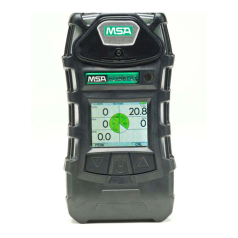
MSA ALTAIR 5X User manual

DELRAY BEACH FIRE-RESCUE DEPARTMENT
QUICK USER GUIDE
MSA ALTAIR 5X
Revised: 7/8/2019
Page: 1 of 2
GENERAL INFORMATION
NOTES
Portable, multi-gas monitor. Detects volatile organic compounds (VOCs),
and combustible, oxygen, and toxic gases.
Technology: Photo-ionization detector (10.6 eV), Catalytic bead LEL
sensor, Electrochemical sensors (CO, H2S, O2, HCN).
Power Source: Rechargeable Li-ion (~14-hr. runtime). Intrinsically safe.
LED Charge Indicator: Red = Charging / Green = Charged / Yellow = Fault
LCD Color Display Screen with backlight (press any button to activate).
3 operation keys (▲, ON/OFF, ▼). Function as “soft keys”, defined
directly above the button.
LEDs Visual Indicators:
oRed (Alarm) = indicates alarm condition or errors
oGreen (Safe) = flashes, indicates instrument normal function and
no alarms are present
oYellow (Fault) = indicates fault conditions
Sensor Life Indicator: warns when sensor’s end-of-life has been reached.
Indicated with a “heart” icon next to sensor/gas-type on main page.
SENSORS
Oxygen (O2)
Combustible (LEL)
Carbon Monoxide (CO)
Hydrogen Sulfide (H2S)
Hydrogen Cyanide (HCN)
PID (VOC - 10.6 eV)
CALIBRATION
Mixed Gas: Pentane (58%
LEL), CO (60 ppm), O2 (15%),
H2S (20 ppm)
Single Gas –HCN: Hydrogen
Cyanide (10.0 ppm)
Single Gas - VOC: Isobutylene
(100.0 ppm)
GENERAL ALARM MESSAGES
MONITOR DISPLAY PAGES
“ADC ERROR”
Analogue measurement error; Contact MSA
Press [▼]button to scroll through display pages.
Press [ON/OFF] button to return to Main Measure Page
Main Measure Page
↳Bump Test Page
↳Peak Reading Page (Press [▲] button to reset value)
↳Minimum Reading Page (Press [▲] button to reset value)
↳STEL Page (Press [▲] button to reset value)
↳TWA Page (Press [▲] button to reset value)
↳Date Page (Displays current date)
↳Last Cal (Displays last calibration date)
↳Change VOC Gas Page
↳Motion Alert Page (Press [▲] or [▼] to turn on/off)
“MEM ERROR”
Memory error; Contact MSA
“PROG ERROR”
Program error; Contact MSA
“RAM ERROR”
RAM error; Contact MSA
“BT ERROR”
Bluetooth error; Contact MSA
“LOW BATTERY
Battery low; recharge battery as soon as possible
“BATTERY ALARM”
Battery completely discharged; recharge battery
“SENSOR MISSING”
Sensor damaged or missing; replace sensor
“NO SENSOR”
No sensors are enabled
Orange, “heart”-icon
Sensor end-of-life warning; replace sensor soon
Red, “heart”- icon
Sensor end-of-life alarm; replace sensor immediately
“PUMP ERROR”
Pump malfunction or flow path blockage
“INVALID CONFIG.”
Sensor installed in incorrect location
BASIC INSTRUMENT OPERATIONS
TURNING UNIT ON
1. Press [ON/OFF] button.
2. Display = “PUMP TEST”, place finger
over pump inlet to block intake
PASS: “PUMP TEST PASS”
FAIL: “PUMP TEST FAIL”
(inspect pump, repeat test)
3. Display = “FRESH AIR SETUP”, press
[▼] button/”YES”begin process.
PASS: “FRESH AIR SETUP PASS”
FAIL: “FRESH AIR SETUP FAIL”
(perform a zero calibration)
4. Once instrument completes start up
process & Main Measure Page appears
in display, instrument is ready for use.
TURNING UNIT OFF
1. Press and hold [ON/OFF] button until
instrument shuts off.
BUMP (FUNCTIONAL) TEST
1. From Main Measure Page, press [▼] button to access Bump Test Page.
2. Attach regulator/tubing to mixed calibration gas cylinder & tubing to instrument’s pump inlet.
3. Display = “BUMP TEST”(O2/LEL/CO/H2S). Press [ON/OFF] button to start the bump test:
PASS: “BUMP TEST PASS”
FAIL: “BUMP TEST FAIL” & failed sensor indicated (Recalibrate instrument)
4. Repeat steps 3 & 4 to bump test individual HCN & VOC sensors, as indicated by the instrument.
Use appropriate calibration gas cylinders: HCN –Hydrogen Cyanide / VOC –Isobutylene
5. Once completed, instrument returns to Main Measurement Page.
ZERO & SPAN CALIBRATION
1. From Main Measurement Page, press and hold [▲] to access the Calibration Page.
2. Display = “ZERO CALIBRATION?”. Press [▼] button to begin zero calibration process:
PASS: “ZERO CALIBRATION PASS” (Display progresses to “SPAN CALIBRATION?”)
FAIL: “ZERO CALIBRATION FAIL” (Repeat zero calibration process)
3. Attach regulator/tubing to mixed calibration gas cylinder & tubing to instrument’s pump inlet.
4. Display = “SPAN CALIBRATION?” (O2/LEL/CO/H2S). Press [▼] button to start calibrate process:
PASS: “SPAN CALIBRATION PASS”
FAIL: “SPAN CALIBRATION FAIL” (Repeat calibration process)
5. Repeat steps 3 & 4 to calibration individual HCN & VOC sensors, as indicated by the instrument.
Use appropriate calibration gas cylinders: HCN –Hydrogen Cyanide / VOC –Isobutylene
6. Once completed, instrument returns to Main Measurement Page.
DELRAY BEACH FIRE-RESCUE DEPARTMENT
QUICK USER GUIDE
MSA ALTAIR 5X
Revised: 7/8/2019
Page: 2 of 2
INSTRUMENT DIAGRAM
1. LEDs
2. Horn
3. Display
4. [▼] Button
5. [ON/OFF] Button
6. [▲] Button
7. MSA Link Communication
8. Pump Inlet
9. Filter
10. Belt Clip
11. Charging Connections
12. Charging Status LED
1. “Soft Key” [▼] Indicator
2. Gas Reading
3. Gas Concentration Units
4. Current Time
5. Motion Alert Symbol –“ON”
6. Wireless –“ON”
7. Combustible Gas Type
Calibration
8. Vibration Alarm Off
9. Horn “OFF” –or- Successful
Bump Test/Calibration Icon
10. LED “OFF”
11. Battery Condition
12. Gas Type
13. “Soft Key” [▲] Indicator
14. Sensor Life Indicator
SENSOR SPECIFICATIONS / ALARM SETTINGS
Sensor
Range
Resolution
“Low Alarm”
“High Alarm”
“STEL Alarm”
“TWA Alarm”
Combustible (LEL)
0-100% LEL
1% LEL
10% LEL
20% LEL
N/A
N/A
Carbon Monoxide (CO)
0-2,000 ppm
1 ppm
35 ppm
200 ppm
100 ppm
25 ppm
Hydrogen Cyanide (HCN)
0-30 ppm
0.5 ppm
4.5 ppm
100 ppm
10.0 ppm
4.5 ppm
Oxygen (02)
0-30% Vol
0.1% Vol
19.5% Vol
23.0 % Vol
N/A
N/A
Hydrogen Sulfide (H2S)
0-200 ppm
1 ppm
10 ppm
20 ppm
15 ppm
10 ppm
PID –VOC 10.6 eV
0-2,000 ppm
0.1 ppm
50.0 ppm
100.0 ppm
25.0 ppm
10.0 ppm
Alarm Indicators: alarm message displays; gas type/reading flashes red; audible alarm sounds; LED flashes red; vibration alarm activates.
Press [▲] button to reset/silence alarms. (Latched alarms will only silence for 5-seconds).
MAINTENANCE / DECONTAMINATION
MSA ALTAIR 5X
OPERATIONS MANUAL
Perform zero/fresh air calibration in a fresh air environment.
Perform a bump test prior to use. Perform instrument calibration weekly or after a failed bump test.
Do not submerge the instrument in water.
Clean the exterior of the device regularly using only a damp cloth. NEVER use solvents or cleaning
solutions of any type.
Replace pump filter when dirty or as needed. Remove clear filter cover on back side of instrument,
and replace with new filters (paper-like filter and fibrous dust filter).
Sampling Line/Tubing: Use only MSA-approved sampling lines. Do not use silicone tubing. Use with
probe and probe filter. Maximum 50 ft length section. Response time approx. 1-second per foot.
Never let end of sampling line touch or go under any liquid surface. If liquid is drawn into the device,
readings will be inaccurate and device can be damaged.
Malfunctioning/damaged instruments should be removed from service, tagged, and reported. Only
approved department members may replace/repair instrument sensors.

Other manuals for ALTAIR 5X

6

Other MSA Measuring Instrument manuals

MSA altair 4 User manual

MSA

MSA altair 4 User manual

MSA PrimaX I User manual

MSA

MSA PrimaX I User manual

MSA APD 2000 Instruction manual

MSA

MSA APD 2000 Instruction manual

MSA altair 4 User manual

MSA

MSA altair 4 User manual

MSA Chillgard 5000 User manual

MSA

MSA Chillgard 5000 User manual

MSA ALTAIR 5X User manual

MSA

MSA ALTAIR 5X User manual

MSA SUPREMA Calibration User manual

MSA

MSA SUPREMA Calibration User manual

MSA ALTAIR 2X User manual

MSA

MSA ALTAIR 2X User manual

MSA Chillgard RT User manual

MSA

MSA Chillgard RT User manual

MSA 487995 User manual

MSA

MSA 487995 User manual

MSA ULTIMA X5000 User manual

MSA

MSA ULTIMA X5000 User manual

MSA Legend Series User manual

MSA

MSA Legend Series User manual

MSA Chillgard LS User manual

MSA

MSA Chillgard LS User manual

MSA ULTIMA XL Series User manual

MSA

MSA ULTIMA XL Series User manual

MSA altair 5 Manual

MSA

MSA altair 5 Manual

MSA ICM 2000 Plus User manual

MSA

MSA ICM 2000 Plus User manual

MSA SUPREMA Touch Installation and operating instructions

MSA

MSA SUPREMA Touch Installation and operating instructions

MSA Ultima X Series Installation and operating instructions

MSA

MSA Ultima X Series Installation and operating instructions

MSA Chemgard User manual

MSA

MSA Chemgard User manual

MSA Mini ID R-1234yf User manual

MSA

MSA Mini ID R-1234yf User manual

MSA PrimaX User manual

MSA

MSA PrimaX User manual

MSA Ultima X Series User manual

MSA

MSA Ultima X Series User manual

MSA MiniOx I User manual

MSA

MSA MiniOx I User manual

MSA altair 4x User manual

MSA

MSA altair 4x User manual

Popular Measuring Instrument manuals by other brands

LCR Elite2 user manual

LCR

LCR Elite2 user manual

Hydac SMU 1000 operating manual

Hydac

Hydac SMU 1000 operating manual

Wachendorff OPUS A3 operating manual

Wachendorff

Wachendorff OPUS A3 operating manual

Hach POCKET COLORIMETER II LCK 325 Application Instruction

Hach

Hach POCKET COLORIMETER II LCK 325 Application Instruction

Kingst LA1016 user guide

Kingst

Kingst LA1016 user guide

F&F WNC-3 manual

F&F

F&F WNC-3 manual

STI CMCP7504 user manual

STI

STI CMCP7504 user manual

Tektronix 067-0599-00 manual

Tektronix

Tektronix 067-0599-00 manual

Zoom H1essential Operation manual

Zoom

Zoom H1essential Operation manual

Hanna Instruments HI 96770C instruction manual

Hanna Instruments

Hanna Instruments HI 96770C instruction manual

Topcon RL-H1Sa instruction manual

Topcon

Topcon RL-H1Sa instruction manual

Schaeffler ProLink CMS user manual

Schaeffler

Schaeffler ProLink CMS user manual

Skil 2100DAF Operating/safety instructions

Skil

Skil 2100DAF Operating/safety instructions

KLEIBER KS 740-LO Operation manual

KLEIBER

KLEIBER KS 740-LO Operation manual

AGFA DX-G user manual

AGFA

AGFA DX-G user manual

Ametek IPS-4-UV user manual

Ametek

Ametek IPS-4-UV user manual

PCME QAL 181 X user manual

PCME

PCME QAL 181 X user manual

Vetek DYNA-LINK ERT Series manual

Vetek

Vetek DYNA-LINK ERT Series manual

manuals.online logo
manuals.online logoBrands
  • About & Mission
  • Contact us
  • Privacy Policy
  • Terms and Conditions

Copyright 2025 Manuals.Online. All Rights Reserved.