MSG Equipment MS004 COM User manual

USER MANUAL
MSG MS004 COM
QUALITY UNIQUENESS
INNOVATION TRAININGSERVICE
WARRANTY
2017.05.16
TEST BENCH FOR DIAGNOSTICS OF ALTERNATORS,
STARTERS AND VOLTAGE REGULATORS

2
1. DESCRIPTION ......................................................................................................................................................3
2. TECHNICAL CHARACTERISTICS........................................................................................................................4
3. RECEIPT AND INSPECTION................................................................................................................................6
4. TEST BENCH DESCRIPTION...............................................................................................................................6
4.1 Mounting Face and Front Panel...........................................................................................................6
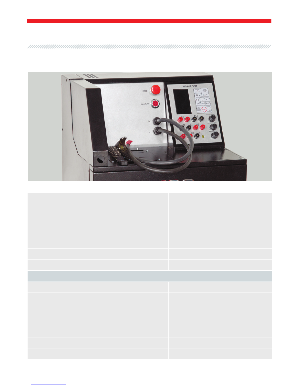
4.2 Control Units..............................................................................................................................................8
4.2.1 Display. Data Output...................................................................................................................9
4.2.2 Buttons............................................................................................................................................14
4.2.3 Terminals ........................................................................................................................................15
4.2.4 Adjustment Knobs........................................................................................................................16
5. SETTING INTO OPERATION..............................................................................................................................16
5.1 Connection.................................................................................................................................................16
6. STEP-BY-STEP INSTRUCTION..........................................................................................................................18
6.1 Alternator Testing.....................................................................................................................................18
6.2 Starter Testing ...........................................................................................................................................20
6.3 Voltage Regulator Testing......................................................................................................................20
7. TEST CERTIFICATE...............................................................................................................................................21
APPENDIX 1.................................................................................................................................................................22
APPENDIX 2.................................................................................................................................................................24
APPENDIX 3.................................................................................................................................................................27
User Manual - Test Bench MSG MS004 COM
CONTENTS

3
User Manual - Test Bench MSG MS004 COM
1. DESCRIPTION
MSG MS004 COM is a table multifunctional test bench. The equipment is used for quick and
quality diagnostics of starters, alternators and voltage regulators without applying any additional
measuring devices.
The test bench possesses high power, thus, units can be diagnosed under different loads. The
equipment has small dimensions, it can be placed both in small service centers and big shops
specialized in selling equipment.
The bench includes the following diagnostic functions: testing of 12V and 24V alternators under load,
12V and 24V voltage regulators, 12V and 24V starters in idle running mode. The device carries out
testing of different alternators under load up to 100A. Power supply is single-phase 220V. Connection
of the 2nd battery is conducted from outside to the terminals on the bench body to achieve power
supply of 24V for more convenient connection. Thus, usage of the 2nd battery is optional.
New algorithms of testing have been implemented, meter accuracy has also been improved.

4
2. TECHNICAL CHARACTERISTICS
Supply voltage, V 230±10% or 110±10%
Supply type Single-phase
Battery model (not concluded in the set) Bosch 0092S50010 or similar
Battery charge 1 Уеs
Battery charge 2 No
Dimensions, mm (length, width, height) 570*490*450
Weight, kg 70
Testing of alternators
Voltage, V 12/24
Drive power, kW 2.2
Load 12V/24V, А 0-100/0-50
Load adjustment Smoothly
Drive rotation, rpm 0-3000
Drive rotation direction Both directions
Transmission type (drive/alternator) Belt
Fig. 1. MS004 COM
User Manual - Test Bench MSG MS004 COM

5
User Manual - Test Bench MSG MS004 COM
Belt type V belt
Poly-V belt
Connection terminals COM (LIN, BSS), P-D, DFM, D+, RLO, C, SIG, F
Read parameters
- Voltage
- Alternating current
- Constant current
- Drive rotation
- COM voltage regulators: protocol, speed
of exchange, protocol type, errors
Testing of starters
Voltage, V 12/24
Power, kW Up to 4
Measured parameters
- Voltage
- Alternating current
- Constant current
Testing of voltage regulators
Voltage, V 12/24
Tested parameters
- Stabilizing voltage
- Current through rotor winding
- COM voltage regulators: protocol, speed
of exchange, protocol type, errors
Voltage meter accuracy, V 0.1
Ampere meter accuracy, А 0.1
Short circuit protection Yes
Short circuit sound alert Yes
Connection terminals COM (LIN, BSS), P-D, DFM, D+, RLO, C, SIG
Total check, sec 30 and longer

6
3. RECEIPT AND INSPECTION
Check the set received. It must contain:
• test bench
• 2 cables for external battery connection (Fig. 19)
• wires to connect an alternator, starter, voltage regulator to the bench sockets
• User Manual
Inspect the test bench for existence of damage. If it is found, please contact either the manufacturer
or trade representative before launching the equipment.
WARNING! In case of obvious damage, use of equipment is forbidden.
Mounting face consists of (Fig. 2):
- Chain fixer 1
- Chain 2
- Belts 3,4
- Covers 5 (battery box cover 1).
The chain fixer (1) is used to latch the chain (2).
The belts (3) and (4) are used to transfer engine torque of the bench on a tested pulley of an
alternator.
The battery 1 is placed under the cover (5).
4. TEST BENCH DESCRIPTION
4.1 M F F P
User Manual - Test Bench MSG MS004 COM
Front panel consists of (Fig. 3):
- Test bench emergency deactivation 6
- Test bench activation 7
- Power cables 8 и 9.

7
User Manual - Test Bench MSG MS004 COM
Fig. 2. MS004 COM - Mounting face
Fig 3. MS004 COM - Front panel

8
Button 6 is specified as STOP. It is used for emergency deactivation of the bench.
Button 7 is specified as ON/OFF. It is used for activation/deactivation of the bench. When button 6
is on, button 7 is out of operation.
Power cable 8 is specified as В-. It is used to connect power negative potential of an alternator or
starter.
Power cable 9 is specified as В+. It is used to connect power positive potential of an alternator or
starter.
4.2 C U
Fig. 4. MS004 COM - Control Panel
User Manual - Test Bench MSG MS004 COM
1 –Display; 2– Sockets; 3– Buttons; 4– Adjustment knobs

9
User Manual - Test Bench MSG MS004 COM
• VOLTAGE, DC: generation voltage indicator (alternator testing) or consuming voltage indicator
(starter testing).
• DFM,%: indicator of load on an alternator.
• AMP, DC: constant current indicator. Generation indicator (alternator testing) or consuming
voltage indicator (starter testing).
• AMP, AC: alternating current indicator.
• TACHOMETER: drive rotation indicator. It is not used when testing a starter.
• D: indicator of set generation voltage when testing alternators with P-D terminal (Fig. 6).
• P: stator winding frequency indicator when testing alternators with P-D terminal (Fig. 6).
• С: indicator of set generation voltage when testing alternators with С terminal (Fig. 7).
• RLO: indicator of set generation voltage when testing alternators with RLO terminal (Fig. 8).
• SIG: indicator of set generation voltage when testing alternators with SIG terminal (Fig. 9).
• PROTOCOL: voltage regulator protocol indicator (alternators with COM terminal only) (Fig. 10).
• BAUD: indicator of data exchange speed indicator of a voltage regulator (alternators with COM
terminal only) (Fig. 10).
• COM: indicator of set generation voltage when testing alternators with COM terminal (Fig. 10).
• ID/TYPE: ID and voltage regulator type indicator (alternators with COM terminal only) (Fig. 10).
• ERROR: voltage regulator error indicator (alternators with COM terminal only) (Fig. 10).
• VOLTAGE REG: indicator of set generation voltage (alternators without a voltage regulator only)
(Fig. 11).
4.2.1 D. D
Display Data Output when Testing an Alternator or Starter
Display Indicators

10
Fig. 5. Display data output when
testing an alternator with D+ terminal
or a starter
Fig. 6. Display data output when
testing an alternator
with P-D terminal
Fig. 7. Display data output when
testing an alternator
with С terminal
Fig. 8. Display data output when
testing an alternator
with RLO terminal
User Manual - Test Bench MSG MS004 COM

11
User Manual - Test Bench MSG MS004 COM
Fig. 9. Display data output when
testing an alternator
with SIG terminal
Fig. 10. Display data output when
testing an alternator with COM (LIN, BSS)
terminal
Fig. 11. Display data output when
testing an alternator without
a voltage regulator F(67)

12
• VOLTAGE, DC: stabilizing voltage indicator of a voltage regulator.
• DFM,%: indicator of load on a voltage regulator.
• AMP, DC: indicator of constant current through winding of simulated rotor.
• D: indicator of set stabilizing voltage of a voltage regulator (voltage regulators with P-D terminal
only) (Fig. 13).
• P: stator winding frequency indicator of a voltage regulator (voltage regulators with P-D terminal
only) (Fig. 13).
• С: indicator of set stabilizing voltage of a voltage regulator (voltage regulators with C terminal
only) (Fig. 14).
• RLO: indicator of set stabilizing voltage of a voltage regulator (voltage regulators with RLO
terminal only) (Fig. 15).
• SIG: indicator of set stabilizing voltage of a voltage regulator (voltage regulators with SIG terminal
only) (Fig. 16).
• PROTOCOL: voltage regulator protocol indicator (voltage regulators with COM terminal only)
(Fig. 17).
• BAUD: indicator of data exchange speed indicator of a voltage regulator (voltage regulators with
COM terminal only) (Fig. 17).
• COM: indicator of set stabilizing voltage of a voltage regulator (voltage regulators with COM
terminal only) (Fig. 17).
• ID/TYPE: ID and voltage regulator type indicator (voltage regulators with COM terminal only)
(Fig. 17).
• ERROR: voltage regulator error indicator (voltage regulators with COM terminal only) (Fig. 17).
Display Data Output when Testing a Voltage Regulator
Display Indicators
User Manual - Test Bench MSG MS004 COM

13
User Manual - Test Bench MSG MS004 COM
Fig. 12. Display data output when
testing a voltage regulator
with L/D+ terminal
Fig. 13. Display data output when
testing a voltage regulator
with P-D terminal
Fig. 14. Display data output when
testing a voltage regulator
with C terminal
Fig. 15. Display data output when
testing a voltage regulator
with RLO terminal

14
Fig. 16. Display data output when
testing a voltage regulator
with SIG terminal
Fig. 17. Display data output when
testing a voltage regulator
with COM terminal
• Alternator & starter tester: activation/deactivation of testing mode of starters and alternators.
The button is lightened in active mode with option to choose voltage and connection terminal.
Testing mode of an alternator with D+ terminal default is on. Operation of the drive belt and
fixing chain is forbidden.
• 12V/24V: buttons to set voltage for testing an alternator, starter, voltage regulator. 12V voltage
default is set. The pressed button is lightened.
• Voltage regulator tester: activation/deactivation of testing mode of voltage regulators. The
button is lightened in active mode with option to choose voltage and connection terminal.
Testing mode of a voltage regulator with D+ terminal default is on.
• P-D,С,RLO,SIG,СОМ:controlsignal injectionto GC sockettotest alternators or voltage regulators
with the corresponding terminal. The button is lightened when the mode is active. To deactivate
the mode, press the button one more time.
• F (67): potential injection to GC socket to test alternators without a voltage regulator. The voltage
is set by positive potential, 2nd terminal of brush assembly is connected to alternator housing.
The button is lightened when the mode is active.
4.2.2 B
User Manual - Test Bench MSG MS004 COM

15
User Manual - Test Bench MSG MS004 COM
• START: activation/deactivation of positive potential through 50 socket to the terminal of starter
solenoid.
• Tighten chain: Button of chain tightening. The tightening is off automatically on sufficient fixing
of a unit.
• Chain release: Button of chain release.
• Tighten belt: Button of drive belt tightening.
• Belt release: Button of drive belt release.
• D+: used fortesting alternators andvoltageregulators withL, D+,I, IL, 61terminals. LAMP indicator
(control lamp simulation on instrument cluster) is lightened next to D+ socket.
• DFM: used to control load on an alternator. It is connected to FR, DFM, M voltage regulator
terminals.
• B+: used for positive potential injection to a voltage regulator. It is connected to IG, S, AS, BVS,
A, 15, 30 voltage regulator terminals.
• GC: used to test alternators with COM, P-D, RLO, C, SIG, 67 terminals.
• В-: used for negative potential injection to a voltage regulator.
• St: used for simulation of rotor winding terminals of an alternator in the mode of testing a
voltage regulator.
• FLD: used to connect voltage regulator brushes or terminals corresponding to the sockets.
• 50: used to test starters. Starter solenoid terminal is connected.
4.2.3 T

16
• REGULATION GC: the knob to adjust generation voltage of an alternator or stabilizing voltage of
a voltage regulator. It is used to connect a voltage regulator or alternator to GC socket. The set
voltage parameters reset on short pressing.
• ELECTRICAL LOAD: the knob to adjust electrical load on an alternator (simulates car consumers).
The set load parameters reset on short pressing.
• ROTATION SPEED: the knob to adjust drive rotation and rotation direction. The drive stops and
electrical load parameters reset on short pressing. Rotation of the adjustment knob to the left
sets drive rotation of the bench to the left (anticlockwise rotation alternators). Rotation of the
adjustment knob to the right sets drive rotation of the bench to the right (clockwise rotation
alternators).
4.2.4 A K
5. SETTING INTO OPERATION
5.1 C
Install the bench in the premises with temperate humidity and temperature. Unscrew 4 bolts and
open cover 5 of the mounting face (Fig. 2). Insert battery 1 (Fig. 18), the model is indicated in the
table ‘Technical Characteristics’. Connect the battery to the relevant wires, according to the marks
of the terminals. Connect the bench to single-phase alternating current supply (supply voltage is
indicated in the table ‘Technical Characteristics’).
Use power cables (Fig. 19) to achieve 24V test voltage, and connect the external battery to the
relevant terminals of the test bench body (Fig. 20). The bench terminals are marked with В+ (battery
positive potential), В- (battery negative potential). The cables are fixed in the corresponding sockets
and turned clockwise until tight. Dismounting of cables is conducted in reversed order.
User Manual - Test Bench MSG MS004 COM

17
User Manual - Test Bench MSG MS004 COM
Fig. 18. MS004COM - Inserted battery with connected terminals
Fig. 19. MS004COM - Power cables to connect the additional battery (battery 2)

18
Fig. 20. MS004COM - Terminals for power cables to connect the external battery
WARNING! Use battery 1 of a specified model only.
WARNING! Observe polarity of the terminal posts, otherwise, it may cause failure of the test
bench. In this case a customer loses warranty package, provided by the manufacturer.
WARNING! Make sure that mains voltage corresponds to the technical characteristics of
the test bench.
WARNING! Make sure that disconnected cables of the additional battery are far enough
from the contact surface.
6. STEPBYSTEP INSTRUCTION
6.1 A T
• Install the unit must on the mounting face.
• The pulley must align with the belt.
• Release the chain to the required length (by pressing the button Chain release on the control
panel), latch the chain over the chain fixer (1) of the mounting face.
User Manual - Test Bench MSG MS004 COM
Before testing the unit, make sure that all bolts are tightened, the test bench is not damaged and
has no cracks.

19
User Manual - Test Bench MSG MS004 COM
• Fix the unit on the mounting face (by pressing the button Tighten chain on the control panel).
Tightening will stop automatically.
• Release the belt to the required length (by pressing the button Belt release), latch the belt over
an alternator pulley. Tighten the belt (by pressing the button Tighten belt) until tension of the belt
is the same as in the car. Belt tension is set manually. Belt tension stops by pressing the button
Tighten belt one more time.
• Connect the power cable (Fig. 3) B- with multi-functional tightening, called ‘crocodile’, to the body
of the tested unit, which is earth, connected to negative terminal of the battery.
• Press the button Alternator & Starter tester, set required voltage with 12V/24V buttons, according
to the technical characteristics of a tested alternator.
• Connect B+ wire (Fig. 3) to the power terminal of an alternator.
• Connect terminals of a voltage regulator to the corresponding sockets of the test bench.
• Press the button of the corresponding terminal on the control panel, according to the connection
terminal of an alternator.
• Rotate the adjustment knob ROTATION SPEED to the left or to the right, depending on rotation
direction of an alternator. Mostly alternators rotate to the left.
• Faultless alternator starts power generation from 700 to 850 drive rotation.
• If voltage regulator connection terminals are P-D, С, RLO, SIG, СОМ, F(67), set preliminary generation
voltage with the adjustment knob REGULATION GC from 13.5V to 14.5V.
• Reach 3 000 rpm maximum drive rotation.
• Increase the load on an alternator. Rotate the adjustment knob ELECTRICAL LOAD clockwise;
anticlockwise rotation decreases the load.
• If voltage regulator connection terminals are L or D+, generation voltage must not go lower than
13.5V under maximum load, and must not go higher than 14.5V under minimum load.
WARNING! Generation voltage must correspond to the technical data of a tested alternator.
WARNING! Discharged batteries may consume up to 50 A of generated current.
On finishing testing of an alternator:
• Reset the set load by short pressing the adjustment knob ELECTRICAL LOAD.
• Stop the drive by short pressing the adjustment knob ROTATION SPEED.
• Deactivate testing mode with Alternator & starter tester button.

20
User Manual - Test Bench MSG MS004 COM
6.2 S T
• Install a starter on the mounting face.
• Release the chain to the required length, latch the chain over the chain fixer of the mounting face.
• Fix the unit on the mounting face. Tightening will stop automatically.
• Connect the power cable B- with multi-functional tightening, called ‘crocodile’, to the body of the
tested unit, which is earth, connected to negative terminal of the battery.
• Press the button Alternator & Starter tester, set required voltage with 12V/24V buttons, according
to the technical characteristics of a tested starter.
• Connect B+ wire to the power terminal of a starter.
• Connect 50 socket to the power terminal of starter solenoid.
• Press START button. A faultless starter will switch on at once.
• Follow the indicators of current and voltage characteristics.
On finishing testing of a starter:
• Deactivate testing mode with Alternator & starter tester button.
• Disconnect the wires from a starter.
• Release the fixing chain.
• Remove a starter from the mounting face.
6.3 V R T
Connect a voltage regulator to the test bench by 2 ways:
1) Connect a voltage regulator to the corresponding outputs of the bench the same way it is
connected to an alternator.
2) Connect a voltage regulator according to APPENDIX 3.
WARNING! When testing 24V voltage regulators, battery 2 is not used.
• Disconnect the wires from an alternator.
• Release the drive belt.
• Release the fixing chain.
• Remove an alternator from the mounting face.
Other manuals for MS004 COM
1
Table of contents
Other MSG Equipment Diagnostic Equipment manuals