MSG Equipment MS004 COM User manual

2021.12.10
MS004 COM
TEST BENCH FOR DIAGNOSTICS OF ALТERNATORS,
STARTERS AND VOLTAGE REGULATORS
USER MANUAL
STANOWISKO DO DIAGNOSTYKI ALTERNATORÓW,
ROZRUSZNIKÓW I REGULATORÓW
INSTRUKCJA OBSŁUGI
СТЕНД ДЛЯ ДИАГНОСТИКИ ГЕНЕРАТОРОВ,
СТАРТЕРОВ И РЕЛЕ–РЕГУЛЯТОРОВ
РУКОВОДСТВО ПО ЭКСПЛУАТАЦИИ
UNIQUENESS
TRAINING
SERVICE
NNOVATION
WARRANTY
QUALITY


English
Test bench MS004 COM
3
CONTENTS
INTRODUCTION....................................................................................................................................................4
1. PURPOSE...........................................................................................................................................................4
2. TECHNICAL CHARACTERISTICS.....................................................................................................................5
3. SUPPLY SLIP....................................................................................................................................................7
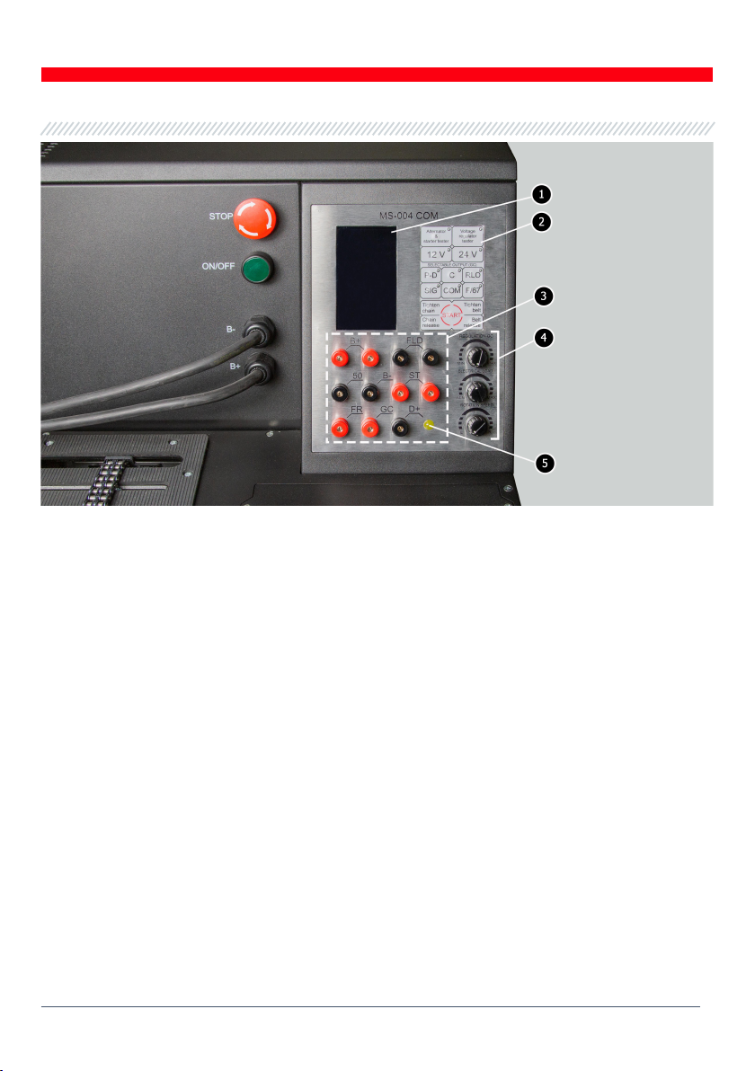
4. TEST BENCH DESCRIPTION.......................................................................................................................... 8
4.1. Displayed data.................................................................................................................................... 11
5. APPROPRIATE USE.......................................................................................................................................15
5.1. Safety Guidelines................................................................................................................................15
5.2. Bench pre-starting procedures......................................................................................................15
5.3. Alternator diagnostics ...................................................................................................................... 17
5.3.1. Installation and connection...................................................................................................... 17
5.3.2. Diagnostics....................................................................................................................................19
5.4. Diagnostics of alternator that doesn’t have the integral voltage regulator ..................... 20
5.5. Diagnostics of voltage regulator................................................................................................... 20
5.5.1. Lamp voltage regulator diagnostics.......................................................................................21
5.5.2. P-D, C, SIG, RLO voltage regulator diagnostics....................................................................21
5.3.3. COM voltage regulator diagnostics.........................................................................................22
5.6. Starter diagnostics ............................................................................................................................22
6. TEST BENCH MAINTENANCE.......................................................................................................................23
6.1. Cleaning and care ..............................................................................................................................23
7. TROUBLESHOOTING GUIDE....................................................................................................................... 24
8. RECYCLING ................................................................................................................................................... 26
APPENDIX 1.........................................................................................................................................................27
APPENDIX 2....................................................................................................................................................... 84
APPENDIX 3....................................................................................................................................................... 87

English
User manual
4
INTRODUCTION
We appreciate you have chosen the products of TM MSG Equipment.
The present user manual consists of the information on the application, supply slip, design,
specifications and rules of usage of test bench MS004 COM.
The design and software are subject to the modifications by the manufacturer without a prior
notice of users.
Prior to using the test bench MS004 COM (hereinafter, “the bench”), study the present user manual
thoroughly. If required, get the special training at bench manufacturer facilities.
1. PURPOSE
The bench is designed for a quick and a first-class diagnostics of automotive alternators, starters,
and voltage regulators - separate from alternators and starters. The bench is powerful enough to
test the units with a wide load range.
The bench functions as follows:
- evaluates the technical condition and identifies the failed element (unit) of 12/24V alternator of
light motor vehicles and trucks;
- checks the performance capacity of voltage regulator - separate from alternator;
- evaluates the technical condition of 12/24V starters of light motor vehicles and trucks at idle.

English
Test bench MS004 COM
5
2. SPECIFICATIONS
Main
Supply voltage, V
230 (60Hz) or 120 (50Hz)
Supply type
Single-phase
Drive power, kW
2.2
Dimensions (L×W×H), mm
570×505×450
Weight, kg
70
Quantity of storage batteries
(not included into supply slip) 2 similar lead-acid by 12V
Battery capacity (not included to set)
from 45 up to 60 Ah
Storage battery automatic charging No.1
Available
Storage battery automatic charging No.2
Not available
Rated voltage of the diagnosed units, V
12, 24
Alternator diagnostics
Diagnosed alternator load, A 12V 0-100
24V 0-50
Load adjustment (0-100%) Smoothly
Drive speed, rpm
0-3000
Drive speed adjustment
Smoothly
Drive type (drive/alternator)
Belt
Belt types
- V-belt
- poly V-belt
Types of diagnosed alternators
COM (LIN, BSS), P-D, RLO, C, SIG, F/67
Measured parameters
- Stabilizing voltage;
- Alternating current;
- Continuous current;
- Drive speed;
For COM voltage regulators:
- Protocol;
- Exchange speed;

English
User manual
6
- ID;
- Type;
- Errors.
Voltage regulator diagnostics
Types of diagnosed voltage regulators
COM (LIN, BSS), P-D, RLO, C, SIG
Parameters of voltage regulator to be
checked
- Stabilizing voltage;
- Control of the performance capacity of
storage battery indicator lamp circuit (D+)
For COM voltage regulators:
- Protocol;
- Exchange speed;
- ID;
- Type;
- Errors.
Short circuit protection
Available
Short circuit alarm
Available
Starter diagnostics
Power of diagnosed starters, kW
up to 4
Measured parameters
- Voltage;
- Alternating current;
- Continuous current.

English
Test bench MS004 COM
7
3. SUPPLY SLIP
The supply slip of bench includes:
Description
Quantity, pc.
Test bench MS004 COM
1
MS0109 - wire kit for the connection with voltage regulator
1
Cable for the connection to the external battery
2
Alternator positive terminal adapter
2
MS0114 - Cutout fuse (type 22x58 mm, current 100А)
1
Warning sign stickers (set)
1
User manual
1

English
User manual
8
4. TEST BENCH DESCRIPTION
The bench consists of the following main elements (fig. 1):
Figure 1 – Bench main elements
1– Working spot.
2 – Protective housing. When the protective housing is up, the diagnostics will be blocked.
3– Power cables.
4 – Button EMERGENCY STOP - crisis shut down of bench supply.
5 – Button OFF/ON - turns on/off the bench supply. If the button EMERGENCY STOP is pressed,
the button OFF/ON is not active.
6– Control panel.
7– Section for the battery location.
8– Height-adjustable legs.

English
Test bench MS004 COM
9
The bench is operated from a working spot (fig.2) that consists of:
Figure 2 – Bench working spot
1– Unit fixing chain.
2– Alternator drive belts: V-belts and poly V-belts.
The control panel (fig. 3) consists of the following main elements:
1– Display – diagnostic data displaying.
2– Control panel - consists of the following buttons:
Altenator & starter tester – on/off the mode of diagnostics of alternators and starters;
Voltage regulator tester – on/off the mode of diagnostics of voltage regulator;
12V/ 24V – setting the rated voltage of the diagnosed unit;
P-D, С, RLO, SIG, СОМ – setting the type of the diagnosed alternator;
F/67 – mode of diagnostics of alternator that doesn’t have the integral voltage regulator;
Tighten chain/Chain release – control of tightening/loosening of unit fixing chain;
Tighten belt/Belt release – control of tightening/loosening of alternator drive belt;
START – switching on/off the terminal 50 for the starter start.

English
User manual
10
Figure 3 – Bench control panel
3– Diagnostic outputs - for the connection to voltage regulator terminals:
В+ – for connection to terminals: 30, B+, IG, S, AS, BVS, A, 15;
FLD» – outputs - for the connection of the brushes of the voltage regulator at diagnostic mode
of voltage regulator or relevant terminals: DF, F, FLD;
В-– negative (earth, terminal 31);
D+ – input of control lamp of voltage regulator. It’s designed for the connection of the
following voltage regulator terminals: D+, L, IL, 61;
ST – output for the connection to the stator outputs (terminals) of voltage regulator: P, S, STA,
Stator;
GC – output connected to the control terminal of the voltage regulator: COM, SIG, etc.;
FR – alternator load control, connected to: FR, DFM, M;
50 – output connected to the starter terminal 50.
4– Regulators:
REGULATION GC – setting of the alternator output voltage. It’s used when connecting the
alternator to the terminal GC.
ELECTRICAL LOAD – setting of the alternator electric load range (imitates car loads). Press to
smoothly switch off the load down to zero level.
ROTATION SPEED – control of speed and rotation direction of drive. Press to stop the drive.
5– Indicator of control lamp operation.

English
Test bench MS004 COM
11
4.1. Displayed data
The information shown on the display when the following types of alternator/voltage regulator is
diagnosed: Lamp, P-D, C, SIG, RLO (see fig. 4 - 8):
VOLTAGE, DC – rate of generation voltage that is provided by alternator/regulator.
DFM, % – duty ratio of PWM signal received through FR channel (on-condition rate of rotor
winding).
АМР, DC – for alternator - it’s a load; for voltage regulator - the rate of the current that is supplied
to the rotor excitation winding; for starter - the rate of the current that is consumed by starter
electric motor.
АМР, АС – rate of the alternator alternating current output, ripples.
ТАСНОМЕТЕR – drive speed rate.
D– rate of generation voltage that is set by the bench.
Р– rate of the on-condition of rotor winding.
Alternator/Starter Voltage regulator
Figure 4 – Bench display during the diagnostics
of alternator/voltage regulator of type Lamp type or starter

English
User manual
12
Alternator Voltage regulator
Figure 5 – Bench display during the diagnostics
of alternator/P-D voltage regulator type
Alternator Voltage regulator
Figure 6 – Bench display during the diagnostics
of alternator/C voltage regulator type

English
Test bench MS004 COM
13
Alternator Voltage regulator
Figure 7 – Bench display during the diagnostics
of alternator/SIG voltage regulator type
Alternator Voltage regulator
Figure 8 – Bench display during the diagnostics
of alternator/RLO voltage regulator type

English
User manual
14
The information shown on the display for the alternators and voltage regulators of COM type
(fig. 9):
Alternator Voltage regulator
Figure 9 – Bench display during the diagnostics
of alternator/voltage regulator of COM type
PROTOCOL – protocol version.
VOLTAGE, DC – voltage rate of generation that is provided by alternator/regulator.
АМР, DC – for alternator - it’s a load; for voltage regulator - the rate of the current that is supplied
to the rotor excitation winding.
АМР, АС – rate of the alternator alternating current output.
ТАСНОМЕТЕR – drive speed rate.
BAUD – speed of data exchange with the voltage regulator.
СОМ – generation voltage rate that is set by the bench.
DFM, % – on-condition rate of rotor winding.
ID/TYPE – voltage regulator identification number. With this number, the electronic control unit
identify the alternator that is assembled.
ERRORS – voltage regulator error indicator. The following errors may happen:
EL (electrical) – electrical failures;
ME (mechanical) – mechanical failures;
TH (thermal) – overheating.

English
Test bench MS004 COM
15
5. APPROPRIATE USE
1. Use the bench for the specified purpose only.
2. Turn off the bench supply with the emergency button (ref. 4, fig. 3) only if the immediate
shutdown of bench supply is required.
3. To prevent the damage and the failure of the bench, do not make any modifications in the bench
in your discretion. Any modifications can be effected by the official manufacturer only. Should the
bench have defects contact the manufacturer or a dealer. The products can be utilized only with
the original spare parts. Non-observance of the mentioned condition withdraws the warranty.
Moreover, MSG Equipment is not responsible for any harm caused by the improper usage of
equipment.
5.1. Safety Guidelines
1. The bench has to be operated by the qualified persons who got the access to operate the
definite bench types and who were instructed on the safe operating procedures and methods.
2. Exit out of the diagnostics mode is obligatory when changing/dismounting the diagnosed unit.
3. While mounting and dismounting of a unit from the bench, to prevent arms from harming, be
more cautious.
4. It’s forbidden to leave the units with running drive on the bench unattended.
5. The bench has to be turned off with the button ON/OFF if the supply is terminated, during the
cleaning and tidying up, as well as in the emergency situations.
6. The work area must always be clean, with good light illumination, and spacious.
7. The operation of the bench that is not grounded is forbidden.
5.2. Bench pre-starting procedures
The bench is supplied packed. Once unpacked, it should be inspected to make sure it has no
damages. If the damages were revealed, prior to the equipment starting, contact the manufacturer
or a dealer.
The bench ensures the operation at the temperature from +10 up to +40 °C and relative air
humidity from 10 up to 90 %.
Prior to the bench operation, connect:
- 12V battery located in the battery section (fig. 1). Follow the power cable markings when
connecting the battery.

English
User manual
16
- 230V electrical mains, grounded.
WARNING!The bench should be used without a circuit breaker. If it’s not possible, the circuit
breaker cutoff current should be higher than 100mA.
- to test the units with the rated operative voltage 24V, the external 12V battery should be
connected to the bench. The battery is connected with the power cables (fig. 10, included to supply
slip) to the connectors on the right side of the bench (fig. 11). Follow the power cable markings
when connecting the battery.
WARNING! The battery located in the bench battery section is enough to test 24V voltage
regulators.
Figure 10. Power cables to connect the external battery
Figure 11. Ports for the connection of the external battery

English
Test bench MS004 COM
17
5.3. Alternator diagnostics
5.3.1. Installation and connection
1. Referring to the alternator OEM, that is commonly indicated on the body or rear cover, find on
the Internet the information on the alternator connector terminals.
Figure 12 illustrates the example of connection layout of Mitsubishi MD375853 alternator.
Figure 12. Mitsubishi MD375853 alternator and connector terminal references
Referring to the connector terminals on the figure 12, first, identify the alternator type (see
Appendix 1 to find the connector terminal references for each alternator type). Now, the terminal
G refers to C alternator type. Next, referring to Appendix 1, check what bench outputs should be
connected with the alternator (connection layout - Table 1).
Table 1 – Connection of Mitsubishi MD375853 alternator to the bench
Terminal
Bench
diagnostic output
G
GC
S
B+
L
D+
F
FR

English
User manual
18
Figure 13 illustrates the example of connection layout of Toyota 2706020230 alternator.
Figure 13. Toyota 2706020230 alternator and connector terminal references
Referring to the connector terminals on the figure 13, first, identify the alternator type (see
Appendix 1). Now, the terminal L refers to Lamp alternator type. Next, referring to Appendix 1,
check what bench outputs should be connected with the alternator (connection layout - Table 2).
Table 2 – Toyota 2706020230 alternator connection
Terminal
Bench
diagnostic output
S
B+
IG
B+
L
D+
DFM (M)
FR
2. Mount the unit on the working spot. The pulley shall be parallel to the used belt.
3. Fix the unit on the working spot, as follows:
3.1. Press Chain release to loosen the chain to the required length.
3.2. Fix the chain to the shoulder in the working spot and press Tighten chain. The tightening
will stop automatically.
4. Put the belt on the alternator pulley.
4.1. Press Belt release to add the required length of the belt. Put the belt on the alternator
pulley and press Tighten belt.
4.2. Tighten the belt until the tension is close to the one in a car. The tension is estimated
subjectively. Press Tighten belt one more time to stop the belt tightening.
5. Screw the adapter on the positive terminal of the alternator.

English
Test bench MS004 COM
19
6. Connect the power cable B- to the unit body, then connect the power cable В+ to the adapter
at the negative terminal of alternator.
5.3.2. Diagnostics
1. Press Alternator & starter tester, then press button 12V/24V to choose the required voltage
referring to the specifications of the diagnosed alternator.
WARNING! With the pressing of the button Alternator & starter tester you start the mode of
diagnostics of Lamp alternator types.
2. Connect the bench diagnostic outputs (ref. 3, fig. 3) with the alternator connector terminals.
3. Choose the relevant alternator type on the control panel.
3.1. If the diagnosed alternator is of COM type, wait until the bench identifies ID and TYPE of
alternator.
3.2. If the alternator has a terminal: L, D+, I, IL, 61, the control lamp indicator shall light up.
3.3. If the diagnosed alternator is of COM type, the notification on the mechanical failure MEC
will appear near the indicator ERROR.
4. Rotate the knob ROTATION SPEED to the left/right referring to the alternator rotation direction
(commonly, alternators rotate clockwise - if you look from pulley side) and set the rotation speed
within the limits of 100 - 150 rpm.
WARNING! For the alternators with the freewheel clutches, be more cautious when choosing
the rotation direction.
4.1. Visually inspect if the alternator rotates properly (the alternator shall not vibrate). If there
are the abnormal noises that may inform on the mechanical failure, stop the diagnostics.
5. Check the rotation speed when the generation starts as follows:
5.1. Set the voltage value 14.5V for 12V alternators and 29V for 24V alternators, rotating the knob
REGULATION GC.
5.2. With ROTATION SPEED knob, increase smoothly the speed until the alternator output voltage
is equal to nominated voltage. Most of the operative alternators start generation from 700 - 850
drive revolutions. Some alternators of COM type start generation at the speed higher than 1200,
besides, there are LRC alternators (Load Response Control) that have the temporary delay at
the output voltage variation.
5.3. For Lamp type alternators, the stabilizing voltage value shall be set within 14 - 14.8 V for 12V
alternators, and within 28 - 29.8 V for 24V alternators.
5.4. If the alternator is equipped with the control lamp indicator it shall go off.

English
User manual
20
5.5. If the diagnosed alternator is of COM type, the mechanical error shall disappear.
6. Check the alternator voltage regulator as follows:
6.1. With the knob ROTATION SPEED, set the speed within 1500-2000 rpm.
6.2*. With the knob REGULATION GC, set smoothly the alternator output voltage within 13 - 15V.
The measured voltage shall vary in proportion to the nominated one.
*For the Lamp type alternators without voltage control, this paragraph is skipped.
7. Check the alternator operation under the load as follows:
7.1. Set the speed within 2500-3000 rpm rotating the knob ROTATION SPEED.
7.2. Rotate the knob ELECTRICAL LOAD to smoothly increase the alternator load. To effectively
check the alternator condition, the current load rate of 50 – 70 A is enough. At the same time,
the output voltage value shall remain constant while the alternating current value (I, AC) in the
circuit B+ shall not exceed 10% of the nominated load value (e.g., at the load of 50A, the value I,
AC shall not exceed 5A).
8. Once the alternator diagnostics is finished, shed the alternator load and stop the drive briefly
pressing ELECTRICAL LOAD and ROTATION SPEED. Then press the button Alternator & starter
tester and dismount the alternator from the bench.
5.4. Diagnostics of alternator
that doesn’t have the integral voltage regulator
The diagnostics of the alternators that don’t have the integral voltage regulator is carried out the
same way as the diagnostics of the Lamp type alternators (see p. 5.3) - with several differences:
1) The following alternator terminal references: DF, F, FLD, 67 shall be connected to GC bench
terminal (fig. 3).
2) Choose the diagnostic mode F/67.
WARNING! The function F/67 allows to check 12V alternators and B-circuit alternator types
only, meaning the alternators that have one of the voltage regulator brushes connected to B-,
and the control of the exciting coil is carried out by the brush connected to B+.
5.5. Diagnostics of voltage regulator
Referring to OEM of voltage regulator, find the information about the terminal references on the
Internet. In addition, you can refer to the Appendix 3 where the most common voltage regulator
Other manuals for MS004 COM
1
Table of contents
Languages:
Other MSG Equipment Diagnostic Equipment manuals