MSG Equipment MS006 User manual

2022.08.02
MS006
OPERATION MANUAL
ON DIAGNOSTICS OF ALTERNATORS
INSTRUKCJA DIAGNOSTYKI
ALTERNATORÓW
ИНСТРУКЦИЯ ПО ДИАГНОСТИКЕ
ГЕНЕРАТОРОВ
UNIQUENESS
TRAINING
SERVICE
NNOVATIO
WARRANTY
QUALITY


English
Operation manual
3
CONTENTS
INTRODUCTION....................................................................................................................................................4
1. TEST BENCH DESCRIPTION...........................................................................................................................5
2. TEST BENCH MENU..........................................................................................................................................7
2.1. Test menu of an alternator................................................................................................................9
3. APPROPRIATE USE........................................................................................................................................13
3.1. Safety regulations..............................................................................................................................14
3.2. Installation and de-installation of the alternator.....................................................................14
3.3. The connection of the bench diagnostic outputs to alternator............................................17
4. ALTERNATOR TESTING.................................................................................................................................21
4.1. Alternator testing in manual mode...............................................................................................21
4.2. Alternator testing in automatic mode..........................................................................................23
APPENDIX 1.........................................................................................................................................................25
CONTACTS.......................................................................................................................................................... 28
APPENDIX 2 ........................................................................................................................................................81

English
Test bench MS006
4
INTRODUCTION
The present operation manual contains the description of the methods on the diagnostics of the
technical condition of the automotive alternators on the test bench MS006 COM (hereinafter, “the
bench”).
WARNING! The manufacturer is not responsible for any damage or injury to human health
resulting from non-compliance with the requirements of this manual.
The bench is designed for the diagnostics of the 12/24V automotive alternators with the different
connection terminals, the 12V alternators of ‘start-stop’ system (Valeo I-StARS) and 24V I-ELOOP
alternators (Mazda). The alternator diagnostics mode is either manual or automatic. The results
of automatic diagnostics can be printed on the portable Bluetooth printer (included into the
supply slip).
Below are the criteria for alternator performance assessment:
- stabilizing voltage;
- control lamp operation;
- FR (displayed FR signal frequency and waveform, voltage regulator feedback).
- the AC pulsation value.
For COM alternator:
- ID;
- Protocol type;
- Data exchange rate;
- LIN protocol type;
- Voltage regulator self-diagnosis faults.

English
Operation manual
5
1. TEST BENCH DESCRIPTION
Figure 1. General view
1 – An alternator drive belt tensioning mechanism.
2 – A mounting face and a chain for fixing an alternator on the test bench.
3 – A protective cover. The cover opening will lead to the procedure emergency shutdown.
4 – Power cables for connection to the alternator.
5 – A control panel.
6 – A Bluetooth printer.
7 – An adapter for the alternator positive terminal.
8 – A set of wires for connection to the voltage regulator of an alternator.

English
Test bench MS006
6
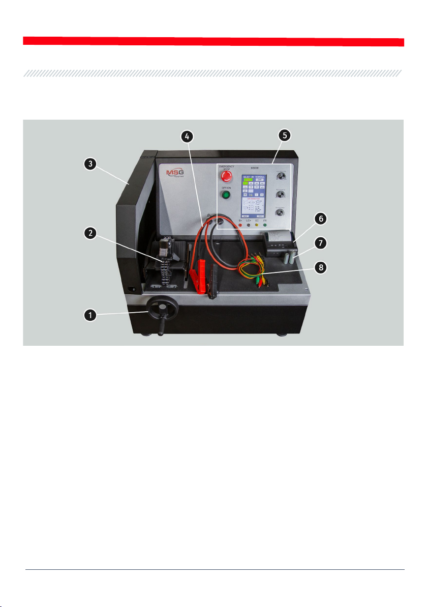
Main elements of the control panel (Fig.2):
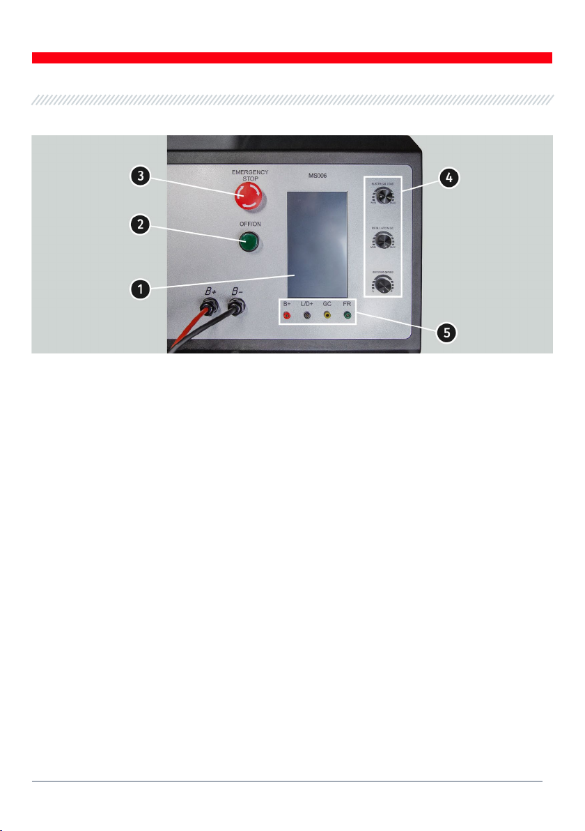
Figure 2. Control panel
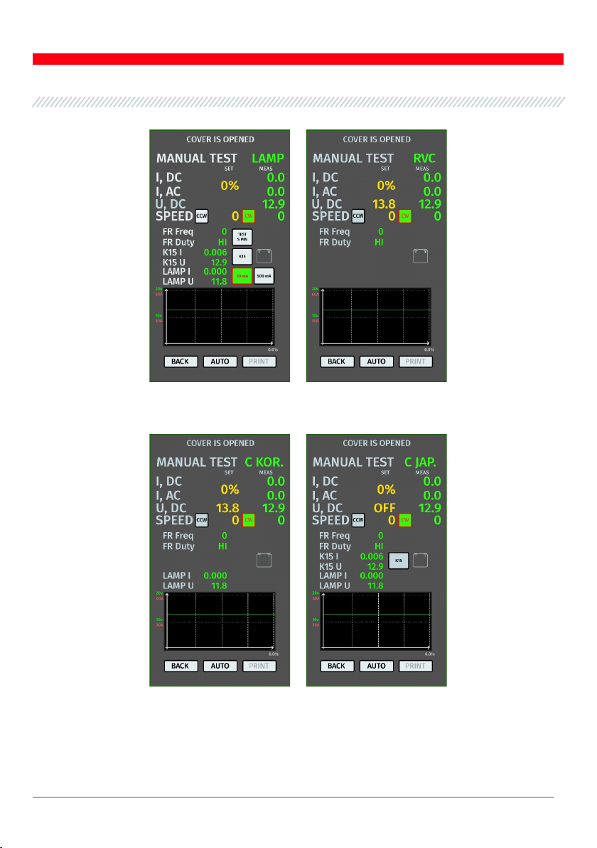
1 – Touch screen: screen to output the parameters of the tested alternator and control the test
bench operation.
2 – “OFF/ON”: button to turn the test bench off/on. Button “OFF/ON” is inoperative when the
“EMERGENCY STOP” button is pressed.
3 – “EMERGENCY STOP”: button for test bench emergency shutdown.
4 – Adjustment knobs: to set and adjust operating parameters:
• «ELECTRICAL LOAD»:knob to set electric load on an alternator (simulates vehicle power
consumers). Press the knob shortly to reset the load to zero smoothly.
• «REGULATION GC»:knob to set/adjust an alternator output voltage. It is used when the
alternator is connected to the “GC” terminal. Press the knob shortly to reset the preset voltage
to the default values (13.8V).
• «ROTATION SPEED»:knob to set/adjust the drive speed (RPM) and rotation direction. Press
the knob shortly to stop the drive.
5 – Diagnostic terminals: to connect the test bench to the voltage regulator terminals:
• «B+»:test bench terminal to connect to the alternator terminals: “B+”, “IG”, “S”, “AS’, “BVS”,
“A”, “15”;
• «L/D+»: output to the voltage regulator control lamp; it is connected to the following
terminals: “L”, “D+”, “I”, “IL”, “61”;
• «GC»:alternator control terminal. It is connected to the terminals “COM”, “LIN”, “D”, “RLO”, “C”,
“G”, “SIG”, “L(RVC)”, “RC”;

English
Operation manual
7
• «FR»:alternator load control; it is connected to the voltage regulator terminals: “FR”, “DFM”,
“M”, “LI”.
A set of four diagnostic cables (Fig.3) is included in the package set.
Figure 3. MS0105 – a set of diagnostic cables for connection to the terminals of the voltage
regulator
Diagnostic cables are connected to the test bench sockets (Fig.2, n.5), observing the color marking.
2. TEST BENCH MENU
The test bench main menu (Fig. 4) contains:
Figure 4. Test bench main menu

English
Test bench MS006
8
«SELECT ALTERNATOR BY TYPE» - menu to select the alternator type;
«SELECT ALTERNATOR BY NUMBER» - menu to select the alternator by its serial number;
«SETTINGS» - test bench parameters menu;
«INFORMATION» - “About the test bench” menu.
Settings menu (Fig. 5) contains:
Figure 5. Settings menu of test bench
«TIME» и «DATE» – time and date setting;
«PRINTER SETTING» – connection of a Bluetooth-printer to the test bench;
«MANUAL TEST SETTING» – manual test mode setting, has several parameters:
– «Enable start check for short circuit» – enable the start check for short circuit;
– «Enable K15 in for COM type terminal» – to enable terminal 15 (ignition) for COM alternators;
– «Reverse rotation» – to reverse the rotation of the drive;
– «Print result in exhibition mode» – to print out test results in presentation mode.
«SET MEASUREMENT COEFFICIENT» provides an access to the bench calibration menu which is
used to adjust the bench by the manufacturer specialists only.
WARNING!It’s forbidden to make any changes in bench calibration without manufacturer
specialist assistance.
«LIN ANALYZING» – Lin bus data reading menu.

English
Operation manual
9
In the menu window SELECT ALTERNATOR BY TYPE (fig. 6) you can choose the rated voltage (12 V
or 24 V) and the type of the diagnosed alternator. The chosen parameter is highlighted.
In case the alternator diagnostics requires the rotation rates that are equal to the rates of a car,
press the buttons “-“ / “+” to set the sheave diameter that is similar to the sheave diameter of a
car. To confirm the settings, press USE.
Press TEST to go to diagnostics mode.
Figure 6. Alternator selection menu
2.1. Test menu of an alternator
When you enter the alternator diagnostics mode, you can read the following information on the
screen (see fig. 7-10):
Yellow indicates set points for testing; green indicates actual (measured) points.
WARNING! “COVER IS OPENED” message signals that the protective cover of the bench is
opened. The diagnostic procedure cannot be activated while the protective cover is opened.

English
Test bench MS006
10
Figure 7. Test menu for alternators LAMP and RVC type
Figure 8. Test menu for alternators C KOR and C JAP type.

English
Operation manual
11
Figure 9. Test menu for alternators P/D and RLO type
Figure 10. Test menu for alternators COM and SIG type

English
Test bench MS006
12
Figure 11. Test menu for alternators I-STARS and I-ELOOP type
Common values for all the types of alternators displayed on the screen:
«I, DC» –direct current value in “B+” circuit.
«I, AC» – alternate current value in “B+” circuit.
«U, DC» – voltage value at “B+” terminal.
«SPEED» – drive rotation indicator (CW – clockwise, CCW – counter clockwise). Direction of the
drive rotation is changed either by clicking on the corresponding icon, or automatically when
the encoder rotates.
«FR Freq»– frequency value of the signal that is received through the communication channel:
FR, DFM, M.
«FR Duty»– duty ratio of the signal that is received through the: FR, DFM, M (the grade of the
on-condition of the rotor winding).
«K15 I» – current value in circuit 15.
«K15 U» – voltage value at terminal 15.
– the button simulates the ignition start signal which is addressed to the alternator
voltage regulator. In case the alternator design includes the output IG, you should
press the button K15 prior to the test.
– test lamp mode. For alternators controlled with the “LAMP” terminal: the test lamp
must be set to 50 mA or 500 mA depending on the alternator type before testing.
– the button initiates the diagnostics of the performance of the terminal S*.
* Through the terminal S, the voltage regulator reads the actual voltage of the battery and
increases the output voltage from alternator - to restore the lost charge.

English
Operation manual
13
The measured voltage and current consumption of the tested alternator are additionally
displayed in the form of oscillograph chart. Green color indicates voltage (U), red color indicates
current (A).
Figure 12. Diagram of the measured voltage and current of the diagnosed alternator.
Values related to COM alternators:
«COM PROT.» – indicator of protocol type of the voltage regulator (BSS, LIN1, or LIN2).
«COM SPEED» – indicator of data transfer rates via LIN protocol. The following speed rates can be
displayed: ” L” -2400 Baud, “M” – 9600 Baud, “H” – 19200 Baud.
«EXCITATION» – current value in the alternator excitation winding. Measured in percentage. It is
read from the voltage regulator via LIN protocol.
«ID» – voltage regulator identification number. The engine control unit identifies the type of the
installed alternator by this number.
«TYPE» – voltage regulator type. The type codes of voltage regulators operating under LIN
protocol are as follows: A1, A2, A3, A4, B1, B2, B3, B4, C3, D1, D2, E1.
«ERRORS» – indicator of errors transmitted by the voltage regulator to the engine control unit.
Types of potential errors: EL – electrical error; MEC – mechanical error; TH – thermal error.
«MANUFACTURE» – manufacturer of the voltage regulator.
3. APPROPRIATE USE
1. Use the test bench as intended only (read INTRODUCTION).
2. When switching the power off, use the “EMERGENCY STOP” button for emergency shutdown only.
3. Connect the test bench diagnostic output terminals to the voltage regulator terminals only.
4. To prevent the damage and the failure of the bench, do not make any modifications in the
bench in your discretion. Any modifications can be effected by the official manufacturer only.
Should the bench have defects contact the manufacturer or a dealer.
5. In case of failures in the operation of the bench, stop further operation and contact the
manufacturer or sales representative.

English
Test bench MS006
14
The manufacturer is not responsible for any damage or injury to human health resulting from
non-compliance with the requirements of this user manual.
3.1. Safety regulations
1. The test bench shall be operated by the workers qualified to work with certain types of
equipment and received appropriate training in the safe operation.
2. In case of a power outage, the test bench shutdown is mandatory when cleaning and lubricating
the bench and in emergencies.
4. To ensure electrical and fire safety PROHIBITED:
- connect the bench to the electrical network having faulty protection against current overloads
or not having such protection;
— use a socket without a grounding contact to connect the bench;
— use extension cords to connect the bench to the electrical network. If the socket is far from the
bench installation site, it is necessary to modify the electrical network and install the socket;
- operation of the bench in defective condition.
- Independently to repair and make changes to the design of the bench, because it can lead to
serious damage to the bench and deprive the right to warranty repair.
5. The units with a running drive must not be left unattended on the test bench.
6. While mounting and dismounting of a unit from the bench, to prevent arms from harming, be
more cautious.
3.2. Installation and de-installation of the alternator
- Install the alternator on the worksite.
Figure 13. Installation of the alternator on the test bench
WARNING! The pulley must be in line with the belt.

English
Operation manual
15
Figure 14. Correct position of the alternator drive belt
- Pass the chain under the operation platform and insert it into the clamp. Rotate the locking
screw clockwise to fix the alternator.
Figure 15. Fixation of the alternator
- Put the belt on the alternator pulley. Tighten the belt until the tension approximately matches
the tension of the belt in the car.
Figure 16. Installation of the belt to the alternator pulley

English
Test bench MS006
16
- Check manually the tightness of the belt (based on personal experience).
Figure 17. Belt tightness check
- Connect the black power cable «B-» to the unit housing.
- Connect the red cable «B+» to the corresponding output of the alternator.
Figure 18. Connection of power cables to the alternator
- Connect the outputs of the alternator voltage regulator to the appropriate outputs of the test
bench (Fig.2, n.5).
The dismantling of alternator is made in the reverse sequence.
WARNING! The dismantling of alternator can be made only when the drive has completely
stopped, and the diagnostics mode is terminated.

English
Operation manual
17
3.3. The connection of the bench diagnostic outputs to
alternator
Assessment of the alternator operability requires a proper connection of the diagnostic outputs
of the test bench.
Alternator OEM which is commonly placed on the unit body or on the rear cover helps to find the
information on the alternator connector terminal identifications in the integral bench database
(fig. 19) or in the Internet.
Figure 19. Database Search Menu and search results
To search the information on alternator in the bench database, do as follows:
1. In the main menu (fig. 4) press SELECT ALTERNATOR BY NUMBER.
2. Enter alternator OEM in the displayed window and press SEARCH.
3. If the bench database finds the required alternator, its type, main technical characteristics,
photo and connection terminal identifications (to enable the display of the connection terminal
identifications press red arrow in the part of the photo). Use the present information and the
information from the Appendix 1 for the proper connection of the bench diagnostic outputs to the
alternator connector.

English
Test bench MS006
18
Below the example of the Bosch 0986049191 alternator connection is illustrated (fig. 20).
Figure 20. Alternator Bosch 0986049191 and connector terminal references
First, determine the alternator type referring to the connector terminals on the fig. 20 (see the
table with the crossing references of connector terminals and alternator types in the Appendix 1)
In this case, the terminal L refers to the alternator type lamp. Then we refer to the Appendix 1 to
check which outputs the alternator should be connected to. The connection chart is in the table
1 below.
Table 1 – Connection of alternator Bosch 0986049191 to the test bench
Alternator
connector terminal
Bench
diagnostic output
Cable
colour code
L
L/D+
black
S
GC
yellow
Below the example of the Toyota 2706020230 alternator connection is illustrated (fig. 21).
Figure 21. Alternator Toyota 2706020230 and connector terminal references
First, determine the alternator type referring to the connector terminals (fig. 21) referring to the
Appendix 1. In this case, the terminal L refers to the alternator type lamp.

English
Operation manual
19
Then we refer to the Appendix 1 to check which outputs the alternator should be connected to.
The connection chart is in the table 2 below.
Table 2 – Connection of alternator Toyota 2706020230
Alternator
connector terminal
Bench
diagnostic output
Cable
colour code
S
GC
yellow
IG
B+
red
L
L/D+
black
DFM (M)
FR
green
Below the example of the Nissan 23100EN000 alternator connection is illustrated (fig. 22).
Figure 22. Alternator Nissan 23100EN000 and connector terminal references
First, determine the alternator type referring to the connector terminals (fig. 22) referring to the
Appendix 1. In this case, the terminal C and a Japanese car application refers to C JAPAN alternator
type. Then we refer to the Appendix 1 to check which outputs the alternator should be connected
to. The connection chart is in the table 3 below.
Table 3 – Connection of alternator Nissan 23100EN000
Alternator
connector terminal
Bench
diagnostic output
Cable
colour code
L
L/D+
black
S
no connection
С
GC
yellow

English
Test bench MS006
20
Below the example of the LUCAS 24157 alternator is illustrated (fig. 23).
Figure 23. Alternator LUCAS 24157 and connector terminal references
First, determine the alternator type referring to the connector terminals (fig. 23) referring to the
Appendix 1. In this case, the terminal D+ refers to the alternator type lamp.
Then we refer to the Appendix 1 to check which outputs the alternator should be connected to.
The connection chart is in the table 4 below.
Table 4 – Connection of alternator LUCAS 24157
Alternator
connector terminal
Bench
diagnostic output
Cable
colour code
D+
L/D+
black
B+
B+ red
B+
There’s a feature of the alternator LUCAS 24157 connection: although there’s only one output B+
on the bench, two outputs B+ have to be connected to the alternator connector. In this case, to
connect the missing output, use the spare connection wire (e.g. green) and couple it with the one
of the red connection wires inserting to the special plug socket (fig. 24).
Figure 24. Connection of two wires to the test bench output
Table of contents
Languages:
Other MSG Equipment Diagnostic Equipment manuals