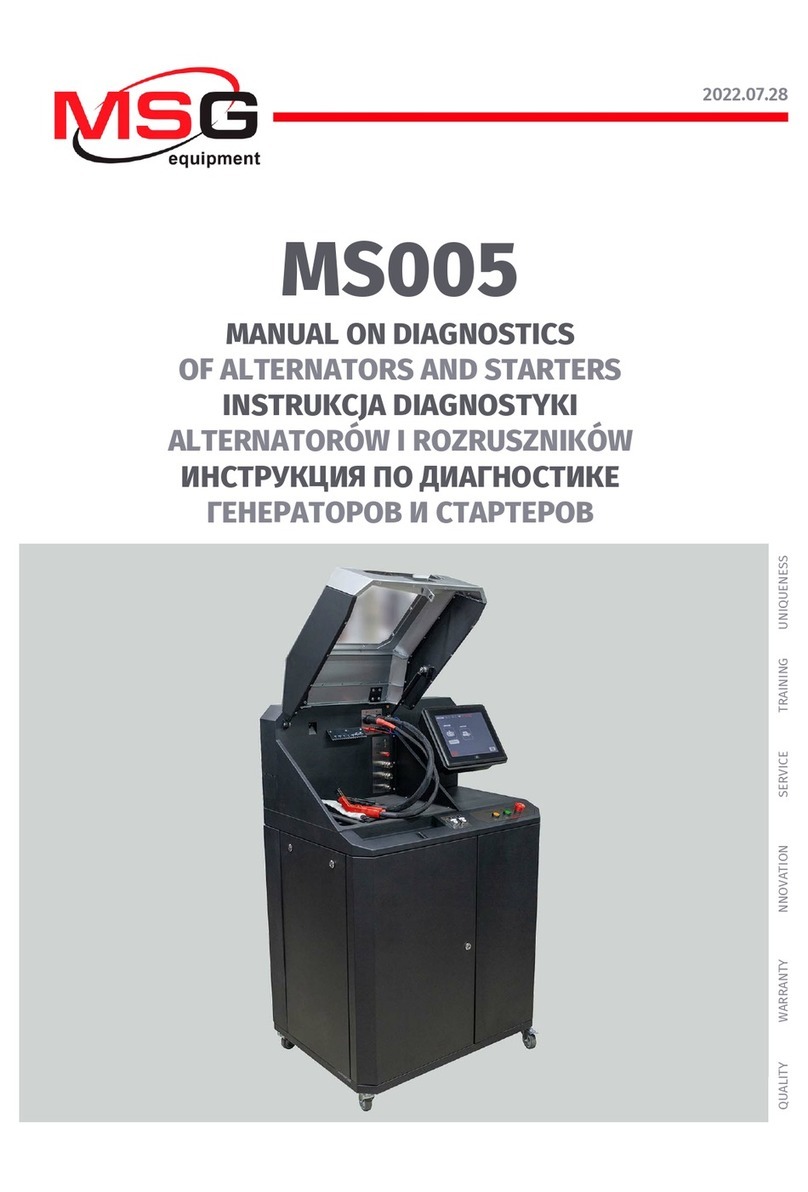
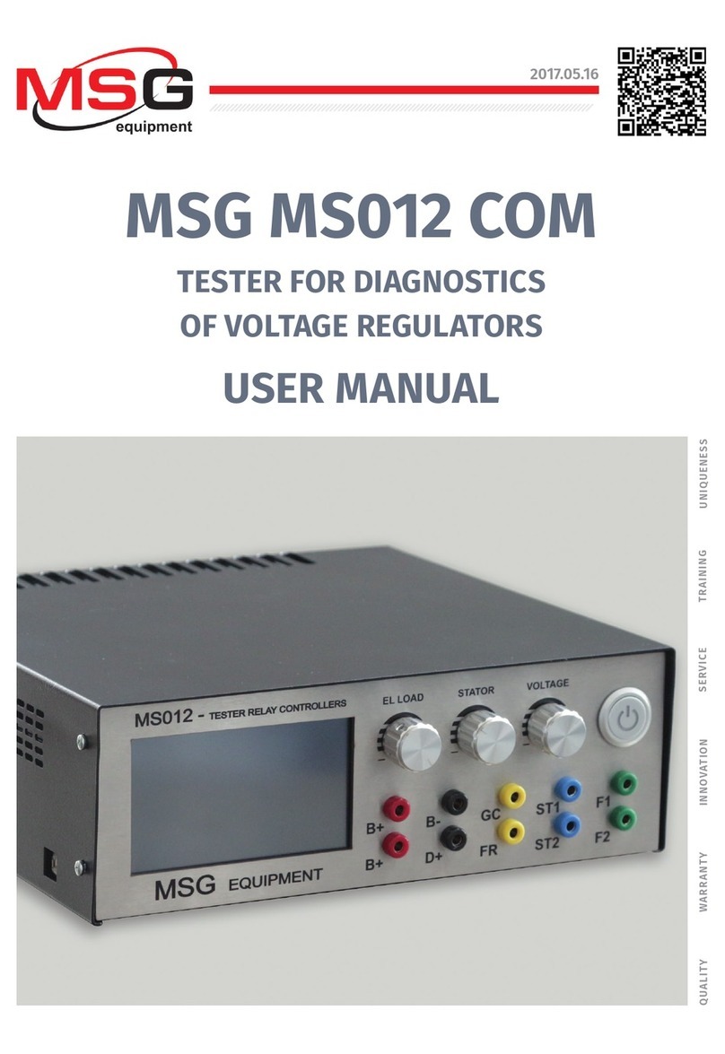
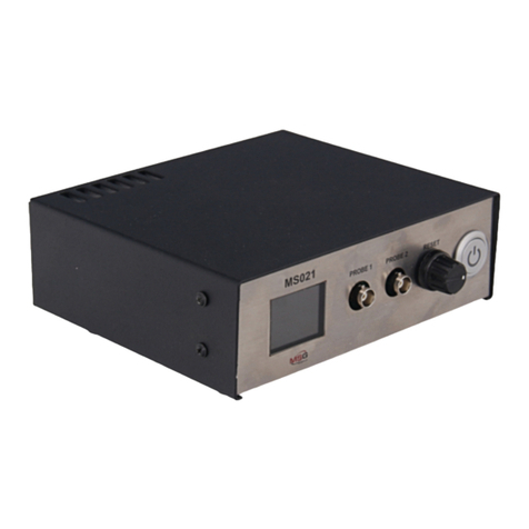
MSG MS012 COM User manual

MSG MS012 COM
ТЕСТЕР ДЛЯ ДИАГНОСТИКИ РЕГУЛЯТОРОВ
НАПРЯЖЕНИЯ АВТОМОБИЛЬНЫХ ГЕНЕРАТОРОВ
РУКОВОДСТВО ПО ЭКСПЛУАТАЦИИ
TESTER FOR DIAGNOSTICS OF VOLTAGE REGULATORS
OF AUTOMOTIVE ALTERNATORS
USER MANUAL
TESTER DO DIAGNOSTYKI REGULATORÓW
NAPIĘCIA ALTERNATORÓW SAMOCHODOWYCH
INSTRUKCJA OBSŁUGI
UNIQUENESS
QUALITY SERVICE
WARR ANTY TRAINING
INNOVATION
2020.08.03


User Manual - Tester MS012 COM
English
INTRODUCTION ...........................................................................................................................................................2
1. PURPOSE ................................................................................................................................................................. 2
2. TECHNICAL CHARACTERISTICS........................................................................................................................... 3
3. COMPLETE EQUIPMENT SET................................................................................................................................4
4. TESTER DESCRIPTION...........................................................................................................................................5
5. INTENDED USAGE................................................................................................................................................... 7
5.1 Safety regulations.......................................................................................................................................... 7
6. TESTER MAINTENANCE .........................................................................................................................................7
6.1 Firmware update............................................................................................................................................8
6.2 Cleaning and care..........................................................................................................................................8
7. MAJOR FAULTS AND TROUBLESHOOTING....................................................................................................... 8
8. DISPOSAL OF THE EQUIPMENT ......................................................................................................................... 9
CONTENTS
1

Thank you for purchasing the product by MSG Equipment.
This Manual contains information about the purpose, complete set, design, operation, technical
characteristics, and instruction for use of Tester MS012 COM.
The manufacturer reserves the right to make changes to the equipment design and rmware
without prior notice to users.
Read carefully this manual before putting Tester MS012 COM (hereinafter referred to as “the
tester”) into operation, get special training at the equipment manufacturing facility if necessary.
Tester MS012 simulates the installation of the voltage regulator to the known good alternator for
evaluation of its performance in different modes, under different loads and resistance values of
the rotor.
The tester is used for evaluation of the technical condition of 12/24V voltage regulators with a
preset value of the rotor resistance and connection terminals «L/FR», «SIG», «RLO», «RVC»,
«C KOREA», «P-D», «COM» («LIN», «BSS»), «C JAPAN», by the following criteria:
•continuity of the control lamp circuit;
•performance of the channel for output voltage setup;
•performance of the feedback channel;
•stabilizing voltage and its correspondence to the set point;
•engine speed rate for activation of the voltage regulator;
•voltage regulator-maintained load.
For COM voltage regulators:
•voltage regulator ID;
•operability of the voltage regulator diagnostic system;
•type of data exchange protocol;
•speed of data exchange.
The tester also helps to select the voltage regulator analog for any particular alternator.
INTRODUCTION
1. PURPOSE
2
User Manual - Tester MS012 COM
English

3
User Manual - Tester MS012 COM
English
2. TECHNICAL CHARACTERISTICS
Dimensions (L×W×H), mm 265×260×92
Weight, kg 4,1
Supply voltage, V 230 or 120
Supply frequency, Hz 50 or 60
Supply type single phase
Maximum power consumption, W 500
Testing of voltage regulators
Voltage of tested regulators, V 12, 24
Resistance of simulated rotor winding, Ohm 12V – from 1.8 to 22
24V – from 4,1 to 22
Frequency of stator windings (simulation of engine
rotation), RPM from 0 to 6000
Load simulation, % from 0 to 100
Tested parameters of voltage regulator
- stabilizing voltage;
- current through rotor winding;
- control lamp (D+).
For COM voltage regulators:
- ID;
- regulator type;
- data exchange speed;
- protocol type;
- errors.

Testing of voltage regulators
Types of tested voltage
regulators
12В «L/FR», «SIG», «RLO», «RVC», «C KOREA»,
«P-D», «COM» («LIN», «BSS»), «C JAPAN»
24В «L/FR», «COM» («LIN», «BSS»)
Control of generation voltage in externally
adjusted voltage regulators yes
Short circuit protection yes
Short circuit sound alert yes
Operating temperature, ℃from +10 to +40
Storage temperature, ℃from 0 to +50
Humidity, relative from 0 to 75%
IP rating IP20
The tester set includes:
-Tester MSG MS012 COM – 1 pc;
-MS0111 – Set of diagnostic wires: 10 pcs/set;
-Supply cable – 1 pc;
-Safety fuse – (type: 5x20mm; current: 2A);
-User Manual – 1 pc.
Inspect the tester. If any damage is found, please contact either the manufacture or sales
representative before launching the equipment.
WARNING! In case of obvious damage, the use of equipment is forbidden.
3. COMPLETE EQUIPMENT SET
4
User Manual - Tester MS012 COM
English

The front panel of the tester (Fig.1) contains:
1 – touch screen for display of the information about the tested voltage regulator and control of
the tester functions;
2 – adjustment knobs for setting the following parameters:
•EL LOAD: adjustment knob with two functions: to set the required resistance of the simulated
rotor in the main menu; to change the load on the simulated alternator and thus, the voltage
regulator, in the range from 0 to 100%.
•STATOR: adjustment knob to change the simulated frequency of stator windings from 0 to 6000
RPMs. The frequency is displayed as vehicle engine speed.
•VOLTAGE: adjustment knob to set the required stabilizing voltage of the voltage regulator. Cannot
be used in the “L/FR” mode.
3 – button OFF/ON: for turning the tester on/off.
4 – terminals: for connection of diagnostic cables and the voltage regulator:
•B+: voltage regulator positive pole (terminals 30 or 15);
•B-: voltage regulator negative pole (earth);
•D+: voltage regulator control lamp terminal for connection of the voltage regulator outputs D+,
L, IL, 61;
5
13
2
4
Figure 1. Tester. Front view.
5
4. TESTER DESCRIPTION
User Manual - Tester MS012 COM
English

•ST1, ST2: terminals simulating stator winding leads of the alternator for connection to the stator
outputs of the voltage regulator.
•GC: terminal for connection to the voltage regulator control terminals.
•FR: load control for connection to the voltage regulator terminals FR, DFM, M.
•F1, F2: terminals simulating the rotor outputs of the alternator for connection of either the
voltage regulator brushes or corresponding outputs of the voltage regulator.
5 – USB port: for connection of the tester to either a computer or a laptop for rmware updating.
The back panel of the tester (Fig.2) is equipped with a safety fuse – 1, and a terminal for
connection of the supply cable – 2.
A set of diagnostic wires (10 pcs) is included in the tester package.
The color marking must be observed when connecting diagnostic wires to the tester terminals.
5
1
Figure 2. Tester. Back view.
Figure 3. MS0111 – Set of diagnostic wires
6
User Manual - Tester MS012 COM
English

1.Use the tester for its intended purpose (read Section 1).
2.The tester is intended for indoor use. Proper environmental conditions for the operation of the
tester (read Section 2) should be observed. Avoid the tester contact with liquids.
3.To avoid damage to the tester, don’t make any changes to its electric diagram. In case of failure,
please contact the technical support service or sales manufacturer.
0nly the personnel that has received special training in safety operation and been authorized to
work with the test benches (devices) of certain types is allowed to use the device.
The tester is intended for a long term operation 24/7. However, regular technical inspection of the
device and routing maintenance will ensure its uptime.
Below are the key points to check during the daily inspection:
-conformity of the environmental conditions to the requirements for tester operation
(temperature, humidity, air pollutants concentration, vibrations, etc.);
-condition of the wires for connection to the tester terminals (visual inspection);
-condition of the supply cable (visual inspection);
Don’t store or use the tester in premises with high temperature and humidity, strong magnetic
eld, the danger of explosion or re. High humidity may harm the device's performance
characteristics.
5. INTENDED USAGE
5.1 Safety regulations
6. TESTER MAINTENANCE
7
WARNING! Procedure for voltage regulator diagnostics with Tester is described in the le
“OPERATION MANUAL: Diagnostics of voltage regulators” and can be downloaded from the
appropriate product detail page on servicems.eu.
User Manual - Tester MS012 COM
English

8
The instruction for updating of the tester program is included in the le “Firmware Update”.
Download the le from the product detail page on servicems.eu.
The below chart contains the description of potential malfunctions and troubleshooting methods:
Malfunction symptom Possible cause Troubleshooting advice
1. Tester doesn't start.
1. Power failure.
2. The power connector came
loose.
3. Burnt safety fuse.
1. Restore power supply.
2. Check the supply cable
connection.
3. Replace the safety fuse
(observe the specied rating).
2. Sound of short circuit alert
(bleep) when the tester is
switched on.
2.1. There is either a connector
short circuit to the tester body
or a short circuit between the
connectors.
2.1. Disconnect the connectors.
3. The tested parameters are
displayed incorrectly.
3.1. Loose connection.
3.2 Damaged diagnostic
cable(s).
3.3. Software error.
3.1. Restore the connection.
3.2. Replace the diagnostic
cable(s).
3.3. Contact the sales
representative.
Use soft tissues or wipe cloths to clean the surface of the device with neutral detergents. Clean
the display with a special ber cloth and a cleaning spray for touch screens. To prevent corrosion,
failure or damage to the tester, do not use any abrasives or solvents.
6.1 SOFTWARE UPDATE
7. MAJOR FAULTS AND TROUBLESHOOTING
6.2 CLEANING AND CARE
User Manual - Tester MS012 COM
English

9
European WEEE Directive 2002/96/EC (Waste Electrical and Electronic Equipment Directive)
applies to the tester disposal.
Obsolete electronic equipment and electric appliances including cables and hardware as well as
batteries and accumulators must be disposed of separately from household wastes.
Use available waste collection systems to dispose of outdated equipment.
Proper disposal of old appliances prevents harm to the environment and personal health.
8. EQUIPMENT DISPOSAL
User Manual - Tester MS012 COM
English

Instrukcja obsługi - tester MS012 COM
Polish
WSTĘP .........................................................................................................................................................................11
1. PRZEZNACZENIE ...................................................................................................................................................11
2. DANE TECHNICZNE ..............................................................................................................................................12
3. ZESTAW ..................................................................................................................................................................13
4. OPIS TESTERA ......................................................................................................................................................14
5. ZASTOSOWANIE ZGODNE Z PRZEZNACZENIEM .......................................................................................... 16
5.1 Wskazówki dotyczące BHP........................................................................................................................ 16
6. OBSŁUGA TESTERA .............................................................................................................................................16
6.1 Aktualizacja oprogramowania..................................................................................................................17
6.2 Czyszczenie i codzienna obsługa............................................................................................................ 17
7. GŁÓWNE USTERKI I METODY ICH USUNIĘCIA............................................................................................... 17
8. UTYLIZACJA .......................................................................................................................................................... 18
SPIS TREŚCI
10

Dziękujemy za wybór produktów rmy MSG Equipment.
Niniejsza Instrukcja obsługi zawiera informacje na temat przeznaczenia, zestawu, konstrukcji,
zasady działania, danych technicznych i zasad eksploatacji testera MS012 COM
Producent zastrzega sobie prawo do zmiany konstrukcji i oprogramowania bez uprzedniego
powiadomienia użytkowników.
Przed użyciem testera MS012 COM (dalej w tekście tester) należy uważnie przeczytać niniejszą
Instrukcję obsługi i w razie potrzeby odbyć specjalne szkolenie w zakładzie produkcyjnym.
Tester umożliwia symulację ustawień regulatora napięcia na notorycznie sprawnym alternatorze
w celu określenia jego działania w różnych trybach, przy różnym obciążeniu i różnych wartościach
rezystancji wirnika.
Tester służy do oceny stanu technicznego regulatorów napięcia 12 i 24 V z zadaną rezystancją
stojana i terminalami przyłączeniowymi „L/FR”, „SIG”, „RLO”, „RVC”, „C KOREA”, „P-D”, „COM” („LIN”,
„BSS”), „C JAPAN” według poniższych kryteriów:
•prawidłowe działanie obwodu lampki kontrolnej;
•prawidłowe działanie kanału ustawienia napięcia;
•prawidłowe działanie kanału sprzężenia zwrotnego (FR, DFM, P);
•wartość i zgodność napięcia stabilizacji;
•obroty silnika, przy których włącza się regulator;
•utrzymanie obciążenia przez regulator.
Opcjonalnie dla regulatorów COM:
•ID regulatora;
•prawidłowe działanie systemu diagnostyki regulatora;
•typ protokołu wymiany danych;
•szybkość wymiany danych.
Tester również umożliwia wybór regulatora analogowego do konkretnego alternatora.
WSTĘP
1. PRZEZNACZENIE
11
Instrukcja obsługi - tester MS012 COM
Polish

12
Instrukcja obsługi - tester MS012 COM
Polish
2. DANE TECHNICZNE
Wymiary (DxSxW), mm 260×265×92
Masa, kg 4,1
Napięcie zasilania, V 230 lub 120
Częstotliwość sieci zasilającej, Hz 50 lub 60
Typ sieci zasilającej Jednofazowa
Pobór mocy nie więcej niż, W 500
Kontrola regulatorów napięcia
Napięcie kontrolowanych regulatorów napięcia, V 12, 24
Rezystancja symulowanego uzwojenia wirnika, Om 12V – od 1.8 do 22
24V – od 4,1 do 22
Częstotliwość uzwojeń stojana (symulacja obrotów silnika),
obr/min od 0 do 6000
Symulowane obciążenie regulatora napięcia, % od 0 do 100
Badane parametry regulatora napięcia
- Napięcie stabilizacji;
- Prąd przez uzwojenie wirnika;
- Lampka kontrolna (D+).
Opcjonalnie dla regulatorów
napięcia COM:
- ID;
- Typ regulatora;
- Szybkość wymiany;
- Typ protokołu wymiany danych;
- Błędy.

Kontrola regulatorów napięcia
Typy badanych regulatorów
napięcia
12В «L/FR», «SIG», «RLO», «RVC», «C KOREA»,
«P-D», «COM» («LIN», «BSS»), «C JAPAN»
24В «L/FR», «COM» («LIN», «BSS»)
Regulacja napięcia generacji w regulatorach
napięcia sterowanych zewnętrznie Tak
Zabezpieczenie przed zwarciem Tak
Temperatura robocza, °C od +10 do +40
Temperatura przechowywania, °C od 0 do +50
Wilgotność względna od 0 + 75%
Stopień ochrony IP20
Zestaw dostawy testera zawiera:
– Tester MSG MS012 COM – 1 szt.;
- MS0111 - zestaw z 10 przewodów diagnostycznych - 1 kompl.;
– przewód zasilający – 1 szt.;
- bezpiecznik topikowy (typ 5x20 mm, prąd 2A) - 1szt.;
- Instrukcja obsługi – 1 szt.;
Przed włączeniem urządzenia należy przeprowadzić oględziny testera, w przypadku stwierdzenia
uszkodzeń należy skontaktować się z producentem lub przedstawicielem handlowym.
OSTRZEŻENIE! W przypadku widocznych uszkodzeń eksploatacja urządzenia jest zabroniona.
3. ZESTAW
13
Instrukcja obsługi - tester MS012 COM
Polish

Na panelu czołowym testera umieszczono (p. rys. 1):
1 - ekran dotykowy, na którym wyświetlane są informacje o badanym regulatorze napięcia i
odbywa się sterowanie funkcjami testera;
2 - regulatory, które dokonują regulacji (ustawienia) parametrów:
• „El LOAD” – regulator pełni 2 funkcje: pozwala wybrać żądaną rezystancję symulowanego
wirnika w menu głównym, umożliwia zmianę obciążenia symulowanego alternatora i odpowiednio
sprawdzanego regulatora napięcia od 0% do 100.
• „STATOR” – regulator umożliwia zmianę symulowanej częstotliwości uzwojeń stojana od 0 do
6000 obr./min. Częstotliwość jest wyświetlana na ekranie jako częstotliwość obrotów silnika
samochodu.
• „VOLTAGE” – regulator umożliwia ustawienie wymaganego napięcia generowanego przez
regulator napięcia. Nie jest używany w trybie „L/FR”.
3 - przycisk „OFF/ON” odpowiedzialny za włączenie/wyłączenie testera;
4 - złącza do podłączenia przewodów diagnostycznych i regulatora napięcia:
• „В+” - plus regulatora napięcia (klema 30 lub klema 15);
• „В-” - minus regulatora napięcia (masa);
• „D+” - wyjście do lampki kontrolnej regulatora napięcia. Przeznaczone do podłączenia wyjść
regulatora napięcia: „D+”, „L”, „IL”, „61”;
5
13
2
4
Rysunek 1. Ogólny widok testera, widok z przodu
14
4. OPIS TESTERA
Instrukcja obsługi - tester MS012 COM
Polish

• „ST1”, „ST2” - wyjście uzwojeń stojana symulowanego alternatora. Podłącza się do wyprowadzeń
stojana regulatora napięcia;
• „GC” - wyjście do podłączenia do terminalu sterowania regulatora napięcia;
• „FR” - kontrola obciążenia. Podłączenie do poniższych terminalów regulatora napięcia: „FR”,
„DFM”, „M”;
• „F1”, „ F2” - wyjścia wirnika symulowanego alternatora. Przeznaczone do podłączenia szczotek
regulatora napięcia lub odpowiadających im wyjść.
5 - złącze USB do podłączenia testera do komputera lub laptopa w celu aktualizacji
oprogramowania.
Na tylnej stronie testera (rys. 2) umieszczony bezpiecznik 1 i złącze przewodu zasilającego 2.
Wraz z testerem dostarczany jest komplet 10 przewodów diagnostycznych (rys. 3).
Przewody diagnostyczne są podłączane do gniazd testera z przestrzeganiem oznaczeń kolorów.
5
1
Rysunek 2. Ogólny widok testera, widok z tyłu
Rysunek 3. MS0111 - komplet przewodów diagnostycznych
15
Instrukcja obsługi - tester MS012 COM
Polish

1. Tester należy stosować wyłącznie zgodnie z jego przeznaczeniem (p. sekcję 1).
2. Tester jest przeznaczony do użytku w pomieszczeniach. Podczas korzystania z testera należy
wziąć pod uwagę warunki środowiskowe określone w sekcji 2. Unikać przedostanie się cieczy do
testera.
3. Aby uniknąć uszkodzenia testera, nie wolno wprowadzać zmiany w schemacie elektrycznym
testera. W przypadku awarii należy skontaktować się z działem pomocy technicznej lub
przedstawicielem handlowym.
Do pracy z testerem dopuszczane są specjalnie przeszkolone osoby, które uzyskały prawo do
pracy na stanowiskach (przyrządach) określonych typów i odbyły szkolenie w zakresie
bezpiecznych technik i metod pracy.
Tester jest przeznaczony do długotrwałej całodobowej pracy. Dla maksymalnego okresu
bezawaryjnej pracy należy jednak regularnie przeprowadzać jego inspekcję i opisane poniżej
prace prolaktyczne z zalecaną częstotliwością.
Poniżej przedstawiono najważniejsze punkty, które należy monitorować podczas codziennej
kontroli:
• dopuszczalność środowiska do eksploatacji stanowiska (temperatura, wilgotność,
zanieczyszczenie powietrza, wibracje itp.).
• sprawność przewodów do podłączenia złączy testera (oględziny).
• sprawność przewodu zasilającego (oględziny).
Nie należy przechowywać ani używać testera w miejscach o wysokiej temperaturze, wilgotności,
zagrożeniu wybuchem lub pożarem, silnym polu magnetycznym. Wysoka wilgotność może
negatywnie wpłynąć na dane techniczne testera.
5. ZASTOSOWANIE ZGODNE Z PRZEZNACZENIEM
5.1 Wskazówki dotyczące BHP
6. OBSŁUGA TESTERA
16
UWAGA! Metodyka diagnostyki regulatorów napięcia za pomocą testera została opisana w
„Instrukcji diagnostyki regulatorów napięcia”, która dostępna do pobrania na stronie
servicems.eu w odpowiedniej karcie towaru.
Instrukcja obsługi - tester MS012 COM
Polish

17
Instrukcja aktualizacji oprogramowania testera jest dołączona do pliku oprogramowania. Plik
oprogramowania jest dostępny do pobrania na stronie internetowej servicems.eu w
odpowiedniej karcie produktu.
Poniżej przedstawiono tabelę z opisem możliwych usterek i sposobów ich usunięcia:
Objaw usterki Możliwe przyczyny Zalecenia dotyczące usunięcia
1. Tester nie włącza się
1. Brak napięcia w sieci.
2. Odłączone złącze zasilania.
3. Spalony bezpiecznik.
1. Przywrócić zasilanie.
2. Sprawdzić, czy przewód
zasilający jest prawidłowo
zamocowany.
3. Wymienić bezpiecznik
zgodnie z podaną wartością
znamionową.
2. Po włączeniu tester emituje
ochronny sygnał zwarcia (pisk). 2.1. Zwarcie odprowadzeń do
obudowy lub między sobą. 2.1. Rozłączyć odprowadzenia.
3. Zmierzone parametry nie są
wyświetlane poprawnie.
3.1. Nieprawidłowy kontakt na
złączu połączeniowym.
3.2 Naruszono integralność
przewodu(-ów)
diagnostycznego(-ych).
3.3. Awaria oprogramowania.
3.1. Przywrócić kontakt.
3.2. Wymienić przewód(ody)
diagnostyczny(e).
3.3. Skontaktować się z
przedstawicielem handlowym.
Do czyszczenia powierzchni testera należy używać miękkich chusteczek lub ściereczek oraz
neutralnych środków czyszczących. Wyświetlacz należy czyścić za pomocą specjalnej włóknistej
ściereczki i sprayu do czyszczenia ekranów wyświetlaczy. W celu uniknięcia korozji, awarii lub
uszkodzenia testera niedopuszczalne jest stosowanie materiałów ściernych i rozpuszczalników.
6.1 Aktualizacja oprogramowania
7. GŁÓWNE USTERKI I METODY ICH USUNIĘCIA
6.2 Czyszczenie i codzienna obsługa
Instrukcja obsługi - tester MS012 COM
Polish

18
W przypadku utylizacji testera obowiązuje europejska dyrektywa 2202/96/EG [WEEE (dyrektywa w
sprawie zużytego sprzętu elektrycznego i elektronicznego)].
Stare urządzenia elektroniczne i urządzenia elektryczne, w tym kable i osprzęt, a także
akumulatory i baterie, powinny być usuwane oddzielnie od odpadów domowych.
- W celu utylizacji odpadów należy skorzystać z dostępnych systemów zwrotu i odbioru.
- Właściwa utylizacja starych urządzeń pozwoli uniknąć szkód dla środowiska i zdrowia
osobistego.
8. UTYLIZACJA
Instrukcja obsługi - tester MS012 COM
Polish
Other manuals for MS012 COM
2
Table of contents
Languages:
Other MSG Test Equipment manuals
Popular Test Equipment manuals by other brands

MONARCH INSTRUMENT
MONARCH INSTRUMENT IllumiNova Series user manual

Rohde & Schwarz
Rohde & Schwarz R&S RTM3000 Getting started

Oakton
Oakton ORPTestr10 instruction manual

Koehler
Koehler K13902 Operation and instruction manual

Keysight Technologies
Keysight Technologies U3020AS22 User's and service guide

Associated
Associated 12-1012 quick start guide